Research Article Open Access
Waste Data Processing Algorithm in Singular Construction Activities: A Case Involving Implementation of NAVFAC P-405
Safeer Ali Abbas Ali1*, Krishnamurthy K2, Arun C3, Ladheedha Nasrin KA2, Simy James2, Neethu Susan Mathew2, Sujatha A2 and Sumayya PM2
1MES Institute of Technology & Management, Research Scholar – Ph.D. Department of Civil Engineering, National Institute of Technology, Calicut, India
2Department of Civil Engineering, National Institute of Technology Calicut, Kerala, India
3National Institute of Construction Management & Research, Goa Campus, Goa, India
- *Corresponding Author:
- Safeer Ali Abbas Ali
Assistant Professor, MES Institute of Technology and Management
Research Scholar – Ph.D. Department of Civil Engineering
National Institute of Technology, Calicut, India
Tel: 0091 9847287314
E-mail: safeeraliabbas@gmail.com
Received Date: December 16, 2016; Accepted Date: December 20, 2016; Published Date: December 25, 2016
Citation: Ali SAA, Krishnamurthy K, Arun C, Ladheedha Nasrin KA, James S, et al. (2016) Waste Data Processing Algorithm in Singular Construction Activities: A Case Involving Implementation of NAVFAC P-405. J Archit Eng Tech 5: 177. doi: 10.4172/2168-9717.1000177
Copyright: © 2016 Ali SAA, et al. This is an open-access article distributed under the terms of the Creative Commons Attribution License, which permits unrestricted use, distribution, and reproduction in any medium, provided the original author and source are credited.
Visit for more related articles at Journal of Architectural Engineering Technology
Abstract
Innovations in construction ‘time waste’ management are scarce. Construction delays are usually caused by time wastes at activity levels, and scholarly studies primarily don't deal in explaining waste at singular activity levels. Experience based heuristics play the most important role in fixing the duration of activities by managers. But, construction activities are prone to highly improbable and complex process flows, making heuristics unreliable. This happens due because the probabilities of construction uncertainties in one project being similar in forthcoming projects are meagerly low. Thus, the experience gained by the project management personnel over the years, may not be handy at predicting actual durations and costs of the forthcoming project with sufficient accuracy.
The only practical solution would be a fixation of cost and time standards for singular construction activities based on the complete history of projects completed and those personnel involved in it. In a nutshell, it would mean globalizing or at least nationalizing heuristic data of delays and wastes in order to facilitate meaningful future predictions.
This can be achieved by devising a mechanism of centralization of construction process related data into a single entity at the national/international level - Data Collection System (DCS). As part of this system, synchronization of personnel and construction site data should take place at every instance a new construction process is activated anywhere within the boundary of existing DCS. A collection of inventory data, material data, labor data, stakeholder data, activity delay data, time waste data, etc. should form the core data in this data center. Data obtained from heuristics should then be converted to mathematical distributions that could then be used for predictions in future construction scenarios. This would result in giving better and better results as the process of data entry proceeds. The scope of this study is limited to construction activities from Indian construction sites involving core and shell in buildings. “Cost overrun” in:
(1) Beam and slab construction,
(2) Column construction and,
(3) Block work is mathematically modeled as probability distributions.
US naval code NAVFAC P-405 is employed for site independent duration calculation. As part of this study, steps on using NAVFAC – 405 in calculating delays are explored in detail. Beta, Normal, and extreme value distributions were seen to fit cost overruns in these activities. This could then be entered into the DCS.
Keywords
Project management; Data-sets; Time data-sets; Construction delays
Introduction
Construction is one amongst the oldest continually existing engineering portfolios. And on the same parallels, construction delays exibit a continual problem that accompanies it to this day. A large number of studies pertaining to finding the causes of these delays have been carried out by researchers [1,2]. But it is a peculiar fact that these studies were not seen to be helping in actually bringing down delays in the process.
Studies on delays can only be fruitful if only detailed construction process (which is highly complex and unique) is taken into account. It would mean singular activities, for example in a building construction:
(a) Concreting of RCC slab or
(b) Laying Steel deformed bars or
(c) Piling of concrete foundation etc. are taken separately for delay mitigation.
Delays and wastes must then be calculated focusing on these single activities. If we divide broadly divide the study on delays, it could be of two types:
(a) Project delays and
(b) Singular activity delays. It can be seen in almost all studies on delays are centered on the first category (Table 1).
| Major causes | |||||
|---|---|---|---|---|---|
| 1 | 2 | 3 | 4 | 5 | |
| Vietnam | Poor site management and supervision | Poor project management assistance | Financial difficulties of the owner | Financial difficulties of the contractor | Design changes |
| Malaysia | Improper Planning | Site management | Inadequate contractor experience | Finance and payment of completed work | Subcontractors |
| South Korea | Public interruptions | Changed site conditions | Failure to provide site | Unrealistic time estimation | Design errors |
| Hong Kong | Inadequate resources due to contractor/lack of capital | Unforeseen ground conditions | Exceptionally low bids | Inexperienced contractor | Works in conflict with existing utilities |
| UAE | Preparation and approval of drawings | Inadequate early planning of project | Slowness of the owner's decision making process | Shortage of manpower | Poor supervision and poor site management |
| Jordan | Financial difficulties faced by the contractor | Too many change orders from the owner | Poor planning and scheduling of the project by the contractor | Presence of unskilled labour | Shortage of technical professionals in the contractor's organization |
| Kuwait | Change orders | Financial constraints | Owner's lack of experience | Materials | Weather |
| Ghana | Monthly payment difficulties | Poor contract management | Material procurement | Inflation | Contractor's financial difficulties |
| Nigeria | Contractor's financial difficulties | Client's cash flow problem | Architect's incomplete drawings | Subcontractor's slow mobilization | Equipment breakdown/ maintenance problem |
Table 1: Major Causes of Delay World Wide (studies show only project based delays).
A unique aspect in construction is that the process flow and stakeholders continuously changes from project to project. This brings us to the point of near-erratic behaviour that exist in activity durations and subsequent overruns. This results in near-impossible scenario to set a theory formulation in construction.
Thus, the only way forward would be simulating the actual process that had taken place in the past at both macro and micro level. Although construction is a continuous event, the present study assumes it as a flow of a large number of discrete events.
The scope of this current study is on developing a method which aid in collecting data pertaining to the singular discrete activities in construction from around the country/countries and integrating it.
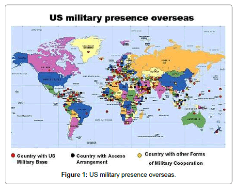
As the primary focus is for reducing delays/wastes, a separate entity âÂ?Â?activity delayâÂ?Â? is defined and formulated. Requirements for uniformity in delay characteristics necessitate calculation of activity durations that can be universally accepted. But, construction process, being considerably dependent on personnel characteristics/environmental aspects, the formulation for a uniform duration calculation is challenging. As part of this study, Navfac P-405, the code used by US Navy is seen to be suitable for duration fixation in construction activities (Figure 1) [3].
As the United States of America has naval bases all over the globe, construction activities in these naval bases are to be designed which is âÂ?Â?locationâÂ?Â? (external factors) independent.
Platform Independence âÂ?Â? An Analogy
An analogy can be thought in the operating systems in computer PCs. A platform-independent software can be run on any operating system be it Windows/Linux/Macintosh/Unix etc. An example of this is drafting software Openoffice. On the Contrary MS-Word or MS-Excel can only be worked upon in MS Windows and will not work on Linux or Unix.
On similar lines to platform independence, âÂ?Â?construction siteâÂ?Â? independence is seen to exist in a code named NAVFAC P-405 (Naval Facility code). Provisions to incorporate diverse site conditionsâÂ?Â? withinâÂ?Â? the designing/scheduling phase is seen to exist. This added advantage makes it almost universally implementable.
This research has incorporated NAVFAC P-405 for calculating the standard duration of selected activities, namely:
(1) Beam and slab construction,
(2) Column construction and
(3) Block work.
Delays are calculated as overruns from these standardized values, which are calculated based only on actual site considerations taken into account.
âÂ?Â?DelayâÂ?Â? in Construction
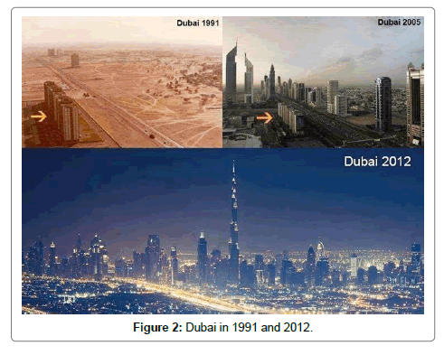
Construction delays form an economic pothole for worldwide economies. For instance, one example of âÂ?Â?rags to richesâÂ?Â? in construction involve Dubai. With no great construction boom in the 1970âÂ?Â?s, Dubai today hosts the worldâÂ?Â?s tallest tower. In thirty years, Dubai construction industry is one of the fastest in the world with roughly 14% of GDP pumped into construction alone. As far as its efficiency is considered, studies by Faridi et al. [4] showed that a staggering 50% of all construction in Dubai is experiencing project delays (Figure 2) [5].
Even the worldâÂ?Â?s tallest tower the âÂ?Â?Burj KhalifaâÂ?Â? experienced a oneyear delay in its opening [6]. With all the major problems that engulf construction, it was supposed to trigger studies and research into the causes and effects of delays and thereby find solutions to reduce it [7,8].
Recent studies on delays and delay formulations
Selected studies conducted in 2013 and 2014 are listed in the following (Tables 1 and 2) Studies pertaining to causes and effects of delays are thus plentiful, Studies by Safeer et al. has ascertained that the causes of delays have to be studied at activity levels, i.e. singular construction activities (construction activities broken down into simpler activities, and waste reduction is done at this basic level) [9,10]. Only such an approach in construction could reduce delays that are carried over from activity to activity causing project delays. Studies for mitigation are, to begin with the basics and go from bottom to top and not the vice versa. Hence the detailed study on each and every construction activity is to be thoroughly brought into the picture in order to begin looking for tools to its mitigation [11,12].
| Sr. No | Author/Researcher | Year | Study features |
|---|---|---|---|
| 1 | Abdullah, Lauri et.al[7] | 2013 | •Need for alternate research approach in construction management. •Simple analysis and evaluations on delays •Study revealed âÂ?Â? Poor Project management as main cause for delay. |
| 2 | Mohamed and Tarek [8] | 2014 | •Studied causes of delay in Egypt •Frequency index, severity index and importance index are developed for various factors. •Ranking of delay was done. |
| 3 | Pablo, Vicente et al [9] | 2014 | •Delays at activity levels and project levels are studies •Interactions between the same are studied. •Reason for non compliance analysis is carried out. •Delay index (DI) for impact on critical and non critical activities are determined. |
| 4 | Muhweri, Acai et al. [10] | 2014 | •Study on factors causing delay in Ugandan buildings •‘Corruption tendencies’ is a key factor in study |
| 5 | Nuhu [11] | 2014 | •Study on preconstruction programming issues & Delay claims •Study shows that bar charts are well preferred by industry professionals over CPM. |
Table 2: Recent studies on delays and delay formulations.
Defining Wastes and Delays as Separate Entities
It could be seen that delays and time waste are separate entities that require mitigation treatments explicitly [12]. Delays are explained as time overrun at activity levels for activity delays. Time waste is the overall waste of resources due to time overruns for that activity. The sum total of wastage from various sources incurred as a result of the delay experienced form time waste. The only mathematical unit successful in quantifying the addition of time waste was seen to be in units of âÂ?Â?moneyâÂ?Â?.
Similarly, âÂ?Â?project delaysâÂ?Â? are defined as time overrun by the entire project from the expected date of completion. Time waste at project level involves the summation of total time waste generated at individual activities in various areas of the project. It becomes imperative to study in detail all these different entities separately for successfully developing a methodology for reducing project delays.
It is a peculiar fact that time waste and delay characteristics are not known to form any basis during fixation of activity duration by the project planners. Neither is these overruns found as an explicit entity in software packages (commonly used for project scheduling). In a large number of construction projects, planners usually employ experience based heuristics in fixing activity durations. But, this method could be seen as scientifically inaccurate or unreliable for duration fixation when it comes to planning scenarios that are not familiar to the planner. It is thus preferable for construction industry researchers to experiment in duration fixing methodologies that are reliable enough by finding a methodology for incorporating expected overruns at planning stage itself.
Existing Methodologies in Activity Scheduling
The usual methods employed for scheduling in the construction process (Hendrickson [13] and Goldratt [14]) as follows (Table 3) Scheduling Methods currently being used.
| No | Scheduling Techniques | Type | Advantages/Limitations |
|---|---|---|---|
| 1 | Bar charts | Deterministic duration | Durations may not be accurate. |
| 2 | Critical Path method (CPM) | Deterministic duration | Durations may not be accurate |
| 3 | Project evaluation review technique | Variable duration | Usually uses Beta distribution only for predicting time period. |
| 4 | Critical chain construction management | Variable duration | Use of Buffer duration helps greatly in uncertainty |
| 5 | Monte-Carlo simulations | Variable duration | Advantageous is data previous data is available |
| 6 | What if simulations | Variable duration | Unpredictable construction activities like foundations. |
Table 3: Scheduling Methods currently being used.
Classifying construction: Developing countries
Today in developing countries such as India, construction could be practically classified as:
a) Formal construction,
b) Informal construction.
Informal construction involves personnel who are not well qualified as per engineering standards. Formal construction may be defined as construction that involves only personnel who are technically qualified as per engineering standards.
Informal construction may also appear to be partial. Major construction firms that give utmost importance to engineering aspects may be forced to become partially informal, in cases where contractors/ sub-contractors become involved (who in turn may lean towards an informal approach). It is high time to bring back construction to engineering standards.
A major solution to this would be strict licensing of skilled personnel for even the smallest jobs in construction activities. If construction is to be improved, it has to adopt mechanization and automation in process and management similar to sister industries such as mechanical production, pharmaceutical, chemical or medical industries. A major difference stems from the fact that the above-mentioned industries do not encourage or take in unqualified personnel for any type of process execution. These can be classified as âÂ?Â?formalâÂ?Â? industries based on the above-mentioned definitions. Problems faced in construction such as chronic cost overrun and time overrun are not seen here.
It may be practically impossible for wholly converting an informal industry such as construction to a formal one overnight. Construction is centuries old and will have its own style of working. But control of work is of utmost importance for proper timely completion. This should require each and every activity and personnel in the construction process, improving himself/itself to engineering standards. The solution proposed is as follows.
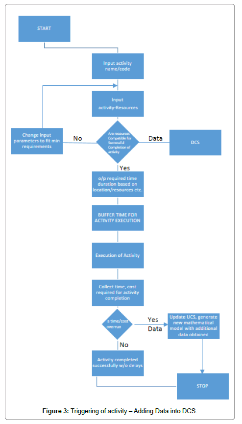
Scattered data from heuristics all around the country are to be integrated into a single framework accessible to all stakeholders including project duration planners. The data collection needs to be automated at activation of any construction activity around the country.
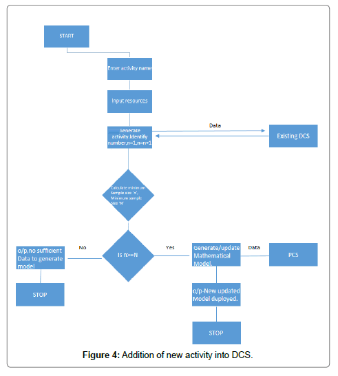
The following algorithm for setting up a data collection system (DCS) is proposed. The chief aim of such a system would be integrating scattered data into a single unit that can be used for dynamic prediction of activity durations. The system would generate better and better data over the course of time as updates flow in.
Data collection system algorithm
The algorithm contains the steps for integrating data over a location of within a specified boundary/area. The construction activities that come within this domain are taken up for modeling. The following 10 step algorithm is proposed.
Step 1: Registering construction activities/stakeholders/location.
Step 2: Setting up Data Collection centers at every city/village.
Step 3: Computerized Integration facility at district levels.
Step 4: Integrating collected data from districts at state levels incorporating state construction codes/rules.
Step 5: Nationalizing data collected in Step 4.
Step 6: Generating mathematical distribution pertaining to each activity/stakeholder/location for local level data and national level data. (Would require powerful mathematical software with high-end services).
Step 7: Prediction tool for simulating chain of construction events. Step 8: Network forming for proper communication at the city level, district level and national level data.
Step 9: Incorporate above for National Data Centre.
Step 10: Setting up National Contractor codes for the time durations of a standard set of activities incorporating details from Data Collection System.
The above algorithm is for setting up a construction specific time/ cost duration. Once the automated system is ready, the activation of construction activity from any location in the country should trigger the data collection system (DCS) to ON mode. The flow charts showing the working of Data collection are shown below (Figures 3 and 4).
Data collection and activities considered: Indian construction sites
As part of this study, three activities pertaining to core and shell in buildings are taken up for investigation.
(1) Beam and slab construction,
(2) Column construction and
(3) Block work construction.
Time overrun in these 3 activities is calculated based on standard duration, hereby termed Quantified Time (QT). The durations are calculated based on United States Naval code NAVFAC P-405 [1]. The special advantage of using it as mentioned earlier is uniformity in formulations that takes into account dynamic elements such as weather, site conditions etc. As sites and personnel differ from place to place, overall history of earlier construction would be beneficial for future calculations. These are to be got from the DCS data base.
Man-day calculation
According to NAVFAC P-405, the formula for determining the quantified time for each activity is based on Man-days required for each activity. The formulations:
MD=(QTY/UNIT SIZE) ÃÂ? (MHRS/UNIT) ÃÂ? DF
Where, MD=Man-Day Estimate which is used to determine the number of men and ratings required on a deployment, and provide the basis to schedule manpower in relation to construction progress. A man-day is a unit of work performed by one man in 8 hours. QTY=Material quantity from material take off (MTO).
UNIT SIZE=Obtained from labour estimating tables.
MHRS/UNIT=Obtained from labour estimating tab. 8=8 hours per one man-day.
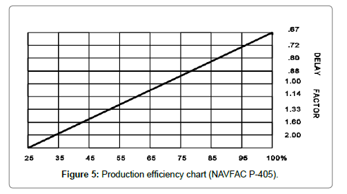
DF=Delay Factor obtained from the production efficiency chart.
First locate PEF on the X-axis and determine the Y value based on the Production efficiency graph. This efficiency depends on various factors such as workload, site area, labour, supervision, job condition, weather, equipment and tactical/logistical (Figure 5).
Duration of each activity:

Where,
MD=Man Day estimate
AF=Availability Factor determines how much of the planned direct.
Labour is available and depends on the deployment site.
ME=Man-Day Equivalent, Planned work hours per day divided by 8 hours (one man-day). Example: a 9-hour workday can be shown 9/8 or 1.125.
CS=crew size which is equal to the planned direct labour (DL).
Dynamic data considered
In the site only 90% of the estimated labour and material were available, therefore an availability factor (AF) equal to 0.9 was considered.
Around 10 hours of construction was taking place per day. Therefore the man day equivalent equal to 10/8=1.25 was used.
The delay factor was obtained from the Production efficiency graph (Figure 5) which is based on average Seabee production efficiency. This efficiency depends on various factors such as workload, site area, labour, supervision, job condition, weather, equipment and tactical/logistical. Based on these conditions we determined the production efficiency to be in the range of 60-70%. Thus, a delay factor of 1.1 was obtained.
According to the data collected from the site, the quantified time for the selected activities is as follows:
Quantified Time (QT)/Activity Duration âÂ?Â? Sample Calculations
Beam and slab construction (Tables 4-7).
| STEEL WORKS | |||
|---|---|---|---|
| Placing reinforcing steel less than 1 inch | |||
| Qty | MHRS | MD | |
| IN METRE | 4560.56 | ||
| IN FEET | 14958.64 | 0.025 | 51.42031 |
| greater than 1inch | |||
| Qty | MHRS | MD | |
| IN METRE | 806.55 | ||
| IN FEET | 2645.484 | 0.03 | 10.91262 |
| Total MD | 62.33294 | ||
Table 4: Beam and slab steel works.
| FORMWORK | ||||
|---|---|---|---|---|
| Area | MHRS | MD | ||
| Beams | Slab | |||
| In m2 | 136.9425 | 151.8992 | ||
| In sq feet | 1473.501 | 1634.435 | ||
| Total | 3107.936 | 0.31 | 132.4758 | |
Table 5: Beam and slab formwork.
| CONCRETING | |||
|---|---|---|---|
| QTY | MHRS | MD | |
| in m3 | 29.69 | ||
| in CD | 38.8939 | 3.315 | 17.72833 |
Table 6: Beam and slab concreting.
| Duration calculation | ||||
|---|---|---|---|---|
| Activity | No. of labours | ME | MD | DURATION |
| Reinforcement | 20 | 1.25 | 62.33294 | 2.7703527 |
| Formwork | 12 | 1.25 | 132.4758 | 9.8130206 |
| Concreting | 6 | 1.25 | 17.72833 | 2.6264186 |
| Total Duration | 12.439439 | |||
Table 7: Beam and slab duration calculations.
Reinforcement and formwork are activities that can be done parallel. Therefore the quantified time for the activity-beam and slab is 9.830206 + 2.626486=12.3939
Cost overrun estimations
Cost overrun estimations are given in Table 8.
| Beam and Slab | ||||||||||
|---|---|---|---|---|---|---|---|---|---|---|
| Act. No | Vol. of work (m3) | Duration | Total cost | Cost Overrun | ||||||
| Estimated | Actual | Duration from NAVFAC | Planned | Actual | % Delay | Planned | Actual | Amount | % | |
| 1 | 26.96 | 29.33 | 11.79567 | 16 | 16 | 35.64298 | 361825 | 407923 | 46098 | 12.74041 |
| 2 | 26.96 | 29.69 | 11.80761 | 16 | 16 | 35.50579 | 371962 | 420949 | 48987 | 13.16989 |
| 3 | 26.96 | 29.61 | 11.80496 | 16 | 17 | 44.00727 | 382099 | 427434 | 45335 | 11.86473 |
| 4 | 26.96 | 29.61 | 11.80496 | 16 | 18 | 52.47829 | 392236 | 445946 | 53710 | 13.69329 |
| 5 | 26.96 | 29.61 | 11.80496 | 16 | 16 | 35.53626 | 392236 | 460241 | 68005 | 17.33778 |
| 6 | 26.96 | 29.61 | 11.80496 | 16 | 17 | 44.00727 | 412510 | 444252 | 31742 | 7.694844 |
| 7 | 26.96 | 29.61 | 11.80496 | 16 | 16 | 35.53626 | 422647 | 436335 | 13688 | 3.238636 |
| 8 | 26.96 | 29.61 | 11.80496 | 16 | 16 | 35.53626 | 432783 | 436349 | 3566 | 0.82397 |
| 9 | 26.96 | 29.45 | 11.79965 | 16 | 15 | 27.1224 | 442920 | 439065 | -3855 | -0.87036 |
| 10 | 26.96 | 29.45 | 11.79965 | 16 | 15 | 27.1224 | 453058 | 439881 | -13177 | -2.90846 |
| 11 | 26.96 | 29.45 | 11.79965 | 16 | 14 | 18.64757 | 463195 | 438251 | -24944 | -5.3852 |
| 12 | 26.96 | 29.45 | 11.79965 | 16 | 14 | 18.64757 | 467885 | 467300 | -585 | -0.12503 |
| 13 | 26.96 | 29.45 | 11.79965 | 16 | 15 | 27.1224 | 463188 | 463088 | -100 | -0.02159 |
| 14 | 26.96 | 29.45 | 11.79965 | 16 | 14 | 18.64757 | 463234 | 474987 | 11753 | 2.537163 |
| 15 | 26.96 | 29.45 | 11.79965 | 16 | 16 | 35.59722 | 464398 | 473789 | 9391 | 2.022188 |
| 16 | 26.96 | 29.45 | 11.79965 | 16 | 16 | 35.59722 | 462920 | 472065 | 9145 | 1.975503 |
| 17 | 26.96 | 29.45 | 11.79965 | 16 | 17 | 44.07205 | 464058 | 475881 | 11823 | 2.547742 |
| median | 4.595618788 | |||||||||
| SD | 11.48501007 | |||||||||
| Confidence Level | 90% | |||||||||
| n | 13.92218979 | |||||||||
Table 8: Cost overrun estimation in beam and slabs.
Adequacy Test Results
The sample size required at the 90 percent confidence level has been determined. It was found from the analysis that the size of the data obtained for each activity at this confidence level is higher than the required sample size at 90% level of confidence. The minimum sample size required and the sizes of the data collected for each activity are given in Table 9.
| Sl. No. | Activity | Sample size required (90% confidence level) |
Available sample size |
|---|---|---|---|
| 1. | Column | 14 | 17 |
| 2. | Beam & Slab | 15 | 17 |
| 3. | Block work | 8 | 17 |
Table 9: Sample size required and available for activity duration.
Mathematical Distribution of Activities âÂ?Â? Cost Overrun
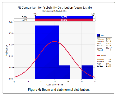
Mathematical distribution of activities âÂ?Â? cost overrun are given in Figure 6 and Table 10.
| Activity | The Probability distribution of Cost Overrun |
| Column | y=beta general(0.31528,0.55241,-7.4603,28.071) |
| Beam and slab | y=normal(1.9823,2.4216) |
| Block work | y=extreme value(-8.2006,7.2829) |
Table 10: Probability distributions for cost overrun of each activity to be entered into DCS.
Data Generated and DCS
The cost overrun mathematical distribution could be used for prediction of cost overruns in future construction. This data is to be further updated when more number of construction take place. The most recent data is to be then made available to the project planner, which makes the planner familiar with overruns in the nearby sites. The planner has then to take decisions with a better view of things to come [15].
As the behaviour of external factors changes from place to place, these types of mathematical distributions are to be generated separately for different localities. The clubbed data then should then be made available to planners of the concerned locality.
Advantages and Limitations of the Algorithm
The algorithm has many advantages that would help in greatly improving the construction process. But it is also challenging so as to see its successful implementation.
Advantages
The data collection system develops/generates activity durations based on actual conditions and does not have the constraints of theory approximations. Hence the estimated durations will be much more reliable than all other currently employed methods.
1. The proposed system has the capability of incorporating behavioral characteristics of stakeholders. It is seen revolutionary in this direction.
2. DCS is iterative, thus improving the capacity of prediction with each construction activity being activated anywhere around the country.
3. DCS has the capability of predicting localized durations and nationalized durations separately. This means that the localized characteristic features of any small area are retained while predicting durations within a local domain.
4. The overall pressure builds on the stakeholders to improve construction process and reduce wastes. This is because of the fact that all data relating to construction are stored and is accessible scrutiny. In the long run process of eliminating low-production stakeholders can be materialized.
5. Mathematical modeling for different entities can be easily done by incorporating a mathematical engine within the system.
6. The algorithm helps in integrating construction as an entity featuring sub-entities that can be taken up for study.
Limitations of DCS
1. The cost of implementation is high, as it requires systems involved at the district level, state level and national level.
2. Resistance from existing industry professionals is expected.
3. Good amount of resources is to be put into the industry for understanding the working of the system.
4. Dedicated personnel would be required for data entry purpose.(Although this is not mandatory).
5. Governmental approval is a must for implementing this system. The bureaucratic delays are expected to take a toll on its actual implementation.
Conclusions and Areas for Future Research
The new system for storing and retrieving data on activity duration discussed in this study benefits the project personnel in predicting the effect of various stakeholders such as sub-contractors and contractors. Moreover, the database developed can be utilized to develop a more realistic benchmark that can be utilized to predict the quantity of work, labor characteristics and conditions of the specific location.
These activity level improvements would then be pivotal in finally eradicating or reducing project delays to a larger extent hence resulting in standardization of construction process. This would help project managers get additional reliable data based on the realistic nature of stakeholders and site conditions resulting in minimization of heuristic prediction of final durations and cost requirements. These developments are expected to make construction process duration and activity duration more predictable and easier to control. The overall merits would then be in minimization of delays and cost overruns. An in-depth study need to be conducted in the following aspects to develop this model to a user-friendly prediction product.
A. Verification and validation of DCS algorithm.
B. Establish a feasible level of construction activity in work breakdown structure.
C. Developing a mathematical model based on the algorithm that can be integrated with existing project management and Building information modelling (BIM) software.
D. Developing a simulation tool to model the randomness of stakeholders, activity durations and related overrun characteristics such as delays and time wastes.
References
- Seabee planner's and estimator's handbook (1994).
- Hoai L, Lee DY, Lee YJ (2008) Delay and cost overrun in Vietnam large construction projects A comparison with other selected countries. KSCE journal of engineering 12: 367-377.
- Fabros C (2008) Bases of Empire The global spread of US military and intelligence bases.
- Faridi AS, Sayegh ESM (2006) Significant factors causing delays in UAE Construction Industry. Construction Management and Economics 24: 1167-1176.
- Smrt News (2013).
- WalidT, Bowman D (2008) Burj Dubai facing 9-month delay.
- Abdullah A, Lauri K, Patricia T (2013) Need for Alternative Research Approaches in Construction ManagementCase ofDelay Studies. Journal of Construction Engineering and Management, ASCE 29: 407-413.
- Mohamed MM, Tarek IE (2014) Analyzing delay causes in Egyptian construction Projects. Journal of Advanced Research 5: 49-55.
- Pablo G, Vicente G, Keith M, Francisco O (2014) Analysis of Causes of Delay and Time Performance in Construction Projects. Journal of Construction Engineering and Management, ASCE 140: 1-9.
- Muhweri L, Acai GO (2014) An Assessment of the Factors Causing Delays on Building Construction Projects in Uganda.International Journal of Construction Engineering and Management 3: 13-23.
- Nuhu B (2014) Understanding Construction Delay Analysis and the Role of Preconstruction Programming. Journal of Construction Engineering and ManagementASCE,pp: 1-10.
- Safeer AAA, Arun C (2012) Time Waste and Delays in Construction A state of the art report. NICMAR Journal of Construction Management.
- Hendrickson C (2000) Advanced Scheduling Techniques.
- Goldratt E (1997) Critical chain. Great Barrington, MA, North River Press.
- AcharyaNK, Lee YD, Im HM (2006) Investigating delayfa ctors in construction industry A Korean perspective. Korean Journal of Construction Engineering and Management 10: 177-190.
Relevant Topics
- Architect
- Architectural Drawing
- Architectural Engineering
- Building design
- Building Information Modeling (BIM)
- Concrete
- Construction
- Construction Engineering
- Construction Estimating Software
- Engineering Drawing
- Fabric Formwork
- Interior Design
- Interior Designing
- Landscape Architecture
- Smart Buildings
- Sociology of Architecture
- Structural Analysis
- Sustainable Design
- Urban Design
- Urban Planner
Recommended Journals
Article Tools
Article Usage
- Total views: 4150
- [From(publication date):
December-2016 - Apr 01, 2025] - Breakdown by view type
- HTML page views : 3271
- PDF downloads : 879

