Research Article Open Access
Variable Impedance Control Based on Impedance Estimation Model with EMG Signals during Extension and Flexion Tasks for a Lower Limb Rehabilitation Robotic System
| Baoping Yuan1*, Masashi Sekine1, Jose Gonzalez1,2, Jose Gomez Tames1and Wenwei Yu1 | |
| 1Department of Medical System Engineering, Chiba University, Chiba, Japan | |
| 2Research Center for Frontier Medical Engineering, Chiba University, Chiba, Japan | |
| Corresponding Author : | Baoping Yuan Department of Medical System Engineering Graduate School of Engineering Chiba University, 1-33, Yayoicho, Inage Ku Chiba, 263-8522, Japan Tel: 81-43-290-3231 E-mail:yuanbaoping1981@gmail.com |
| Received July 23, 2013; Accepted August 23, 2013; Published August 26, 2013 | |
| Citation: Yuan B, Sekine M, Gonzalez J, Tames JG, Yu W (2013) Variable Impedance Control Based on Impedance Estimation Model with EMG Signals during Extension and Flexion Tasks for a Lower Limb Rehabilitation Robotic System. J Nov Physiother 3: 178. doi: 10.4172/2165-7025.1000178 | |
| Copyright: © 2013 Yuan B, et al. This is an open-access article distributed under the terms of the Creative Commons Attribution License, which permits unrestricted use, distribution, and reproduction in any medium, provided the original author and source are credited. | |
Visit for more related articles at Journal of Novel Physiotherapies
Abstract
Rehabilitation robotic devices could be used as an effective tool to restore impaired motion functionality. Due to the human-robot cooperative nature of rehabilitation, these systems are expected to be user-oriented i.e., they should be controlled considering users dynamic characteristics. In this article, we proposed a variable impedance control, in which desired impedance of a system was setup to match human joint stiffness estimated from Electromyogram (EMG) signals recorded. Two experiments were performed in this work. The objective of the first experiment (Experiment-1) was to study the relationship between EMG and changing impedance in knee joint extension and flexion tasks. Based on the recorded data, a nonlinear model was proposed to express the relationship between EMG and changing impedance. The results show that Root Mean Square of the EMG signals (RMS-EMG) of target muscles increases, as specified elastic modulus increases for both tasks, but there is a significant difference (p<0.01, t-test) between the extension and flexion task. The second experiment (Experiment-2) was to confirm the effectiveness of the variable impedance control with the motion-dependent models acquired in Experiment-1. Four different control policies were tested, i.e., NA: No Assist; FO: using EMG-impedance model from the Flexion Task; EO: using EMG-impedance graph from the Extension Task; FE: using two EMG-impedance models from Flexion and Extension task correspondently. Results indicate that the proposed control model (FE) achieved a smaller discrepancy (p<0.01, t-test) between desired angle and the reached angle than the control with EO or NA cases. Moreover, a small sum of RMS_EMG from the variable impedance control with motion- dependent models denoted less effort required than the NA (p<0.01, t-test) case or the control with FO (p<0.01, t-test). Results also indicate that the proposed nonlinear and motion-dependent variable impedance control method achieved a smaller angular discrepancy (P<0.05, t-test) than linear variable impedance control.
| Keywords |
| Rehabilitation robotic system; Human-robot cooperative; Variable impedance control; Electromyogram; Root mean square of the EMG signals |
| Introduction |
| Recently with rapid aging of population and declining birthrate in many countries, public health burden associated with strokerelated disability in lower limbs has been increasing year by year [1,2]. The stroke could lead to life-long dependency on caregivers and a tremendous decrease of the quality of life (QOL). These factors are driving research work for more cost-effective methods for poststroke rehabilitation, including robotic devices that provide movement therapies. As an effective tool for therapists, rehabilitation medicine and technology have been playing a more and more important role in dealing with those social issues. Moreover, a number of rehabilitation robotic systems have been developed for the purpose of improving motor function after stroke over the past few years [3,4]. Their therapeutic effects have been proved by numbers of studies: they could not only improve stroke patients√ʬ?¬? Range Of Motion (ROM), strengthen muscle, but also rebuild patients√ʬ?¬? life confidence and help them restore their impaired motor functions to improve their QOL [5]. |
| Rehabilitation robotic systems could be divided into 3 categories according to the type of motion support [6,7]: 1) continuous passive motion [8,9], 2) active-resisted movement [10], 3) active-assisted movement [11,12]. Among these, active-assisted movement has been proved to be the more effective system for motor functional improvement than other two methods on both the upper limbs and lower limbs [6,11,12]. However, this motion support requires rehabilitation robotic systems to support active movement in cooperation with human subjects. |
| Impedance control has been employed recently for this type of robotic systems to cooperate with human subjects√ʬ?¬? motion, reacting to their voluntary intention detected from EMG or torque sensors [13,14]. The Mit-Manus has been implemented based on impedance control to ensure a compliant trajectory [15] and the assistance output torque was produced from the angular error between the desired position and the patient√ʬ?¬?s position, with the aim to reach the desired position accurately. The HAL-1 proposed an assistance feedback control scheme that could generate an angular displacement and provide a ramp torque in the movement in response to a patient√ʬ?¬?s torque by using impedance control based on the output of torque sensors [13]. These devices can reach the desired position precisely and rapidly with lower power. However, a torque sensor was used to decide the parameter of control system with an invariable relationship, which was determined by experiences and, in that case, the same control parameter was adopted, both the extension task and flexion task, the control system was unstable if force output of the two target muscle varied greatly. Moreover, if a subject has a limited ROM by some reasons, and the torque output could not be measured, these systems would provide passive movement rather than cooperative movement. |
| EMG, as a bio-signal source, could be used to detect muscle activity, reflected characteristics of muscle activities in the real-time. Some researchers have applied EMG signals to estimate the changing impedance of knee joint in rehabilitation robotic system. Artificial neural networks have mainly been used to verify the relationship between the EMG signals and the parameter of impedance control [16]. It could be used to estimate the parameters of impedance control by using EMG signals. However such approaches have limited ability to adapt to changing physiological conditions, and being of a black-box structure, do not permit stability and performance analysis [11]. |
| There were also some other methods to clarify the relationship between EMG signals and changing impedance in a joint. Kusumoto et al. [17] studied the impedance parameters of human thumb muscle by using EMG signals based on isometric contraction at a fixed angle [18]. The impedance of thumb muscle was well calculated by increasing the power of contraction. However, this method could not reflect the dynamic characteristics of muscle because of the experimental condition of isometric contraction. Nichols and Houk [19] followed the methods that applied electrical stimulation to isolated muscle, to estimate the impedance parameter [20]. An accurate model was proposed at different conditions, such as different length of muscle, and stimulus intensities. However, this invasive method used animals as subjects, which was not clear how this could be transferred to humans. |
| Furthermore, power assist control for a walking aid system based on EMG signals and impedance control have been proposed by some researchers [21,22]. In this case, a virtual torque derived from the EMG signals was adopted as a basic control method, thus the system can help the operator to achieve the intended motion. However, in those studies the relationship between control parameters, i.e., impedance, and EMG was assumed as invariable not only for different moment in one motion, but also for different motions, such as extension and flexion. Few studies employed changing impedance, but limited to linear [23] and motion-independent [14,24] impedance values, determined through subjective opinion of engineers, therapists or even subjects. |
| However, if a fixed parameter of impedance control does not match with operator√ʬ?¬?s joint stiffness in one certain or different direction of motions, the cooperative system would become unstable, even vibrating, and it would be difficult for the system to reach a target trajectory, that is, the position error would be quite big [23]. Therefore, a variable impedance controller with motion-dependent and nonlinear impedance control model should be designed considering target muscles dynamic characteristics to make the robotic system more useroriented in human-robot cooperative tasks. |
| The aim of this study was to investigate the possibility of impedance estimation from EMG signals recorded during extension task and flexion task, and the effectiveness of the variable impedance control based on the estimated impedance for a lower limb rehabilitation robotic system. For this purpose, two experiments were conducted in this study. The primary objective of the first experiment (Experiment-1) was to study the relationship between EMG and changing impedance in knee joint extension task and flexion task. In this experiment, EMG signals were measured, and normalized RMS_EMG was paired with increasing changing designated impedance, and anon linear model was proposed to fit the recorded data to express the relationship between them. The second experiment (Experiment-2) was to confirm the effectiveness of variable impedance control with the models acquired from the Experiment-1. The discrepancy between desired and reached angular trajectories, and sum of RMS_EMG of target muscles were used to evaluate the validity of our proposed nonlinear variable impedance control method. |
| Methods |
| An Overview of the Lowerlimb rehabilitation system |
| The lower limb rehabilitation robotic system is composed of 3 parts: |
| An interface: It contains a monitor for visual information, such as experiment instruction, angular position for feedback, raw recorded signals. The display of the visual information and measurement of the signals were implemented in LabVIEW9.0 (A/D: USB-6225, National Instruments, and USA). |
| A controller: It realizes impedance estimation with EMG signals and variable impedance control, which is described in detail in sub-section B. The controller is implemented using a PC (CF-B10, Panasonic, Japan). |
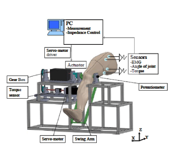
| Hardware of the robotic system: It consists of a swing arm (lower limb holder), a torque sensor, a reduction gear box, a servo motor (SGMAH-02AAA21, Yasukawa Electric, Japan), which was driven by a motor driver (SGDM-02BDA Yasukawa Electric, Japan). |
| The configuration of the rehabilitation robotic system is shown in (Figure 1). The angle of swing arm was calculated from the readings of a potentiometer (5K ohm, Nidec Servo, Japan), and input (voltage value) to the motor was calculated from variable impedance controller. |
| For safety reasons, 4 safety measures were taken to protect subjects during all the following experiments. First, an emergency stop button could be pressed by a subject to stop the servo-motor immediately if needed. Second, the output torque was limited to arrange of 0 N√?¬?m to 50N√?¬?m by the software program, and the operation would be stopped if the motor exceeded this range. Third, the maximum speed of lower limb holder was limited to 2rad/s by the servo-motor driver. Fourth, two mechanical stops were used to limit the rotation range of the swing arm. |
| Variable impedance control |
| The model of the swing arm and knee joint could be described as below [25]: |
 (1) (1) |
| where, Io is an inertia moment, θ is the angle of the swing arm, Bo is a viscous coefficient, ko is an elastic modulus, MgL is an item for gravitational effects, fr is an item for friction effects, τe is an external torque, τ is a torque command vector. |
| Assume that the desired impedance control model was given by: |
 (2) (2) |
| In this equation, Id is a desired inertia moment, Bd is a desired viscous coefficient; Kd is a desired elastic modulus, θd is a desired angle position, τe is the external torque. Integrating Equation (1) and (2), the torque command output for the impedance control could be derived as Equation (3). |
 (3) (3) |
| In order to implement a variable impedance control, Kd and Bd should be determined or estimated. Firstly, the static synthetic impedance of knee joint and swing arm was identified using least squares method, and the influence of those was compensated to accurately estimate Kd and Bd. Then, assuming these two variable parameters could be approximated by Equation (4). |
 (4) (4) |
| EMG-signal processing |
| The EMG signals were sampled with surface EMG-sensors (TYE- 100, Tsukasa Kiko Engineering, Japan), placed on the Rectus Femor is muscle and Semi membranous muscle of lower limb of subject. EMG signals were amplified with a gain of 1000 and processed by a band-pass filter (10 to 1000Hz). The sampling rate is 3000Hz. The EMG signals was then full-wave rectified and smooth educing a moving average filter with a window size of 6. Then, Root mean square of EMG (RMS_EMG) was calculated as Equation (5). |
 (5) (5) |
| Where T is a time span, t is a variable of integration, and a sampling space was settled as 0.1s in this study. The processed EMG signals were then normalized to the range 0-1 by the value MVC (Maximum Voluntary Contraction) for % EMG as in the following Equation (6) [26]. |
 (6) (6) |
| Where, (RMS_EMG)t is the RMS_EMG of the target muscle, (RMS_ EMG)t_MVC is the maximal value of target muscle during its maximal voluntary contractions by 3 times measurement and (RMS_EMG)t_rest is the average RMS_EMG value of target muscle during the resting state. |
| Moreover, the differential values of EMG of target muscles between the agonist and antagonist as MVC% was used in this study as Equation (7). |
 (7) (7) |
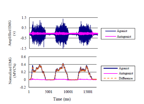
| Where, % EMGagonist is the RMS_EMG of agonist muscle (Rectus Femoris during extension, or Semi membranous during flexion), %EMGantagonist is the RMS_EMG of antagonist muscle (Semi membranous during extension, or Rectus Femor is during flexion). An example of EMG-signal processing procedures when doing experimental extension task is shown as in Figure 2. |
| Modeling and caculating Kd |
| In the following experiments, EMG of the Rectus Femor in muscle and Semi membranous muscle were measured, and the differential values of normalized RMS_EMG between the two muscles were calculated, and used to quantify the relationship between the EMG and changing impedance in knee joint. However, to verify the changing impedance in knee joint, the static synthetic impedance of knee joint and swing arm has been identified using least squares method, and the influence of it was compensated in the all following experiments. Therefore, in this the changing impedance is defined as the active mechanical impedance (viscous coefficient and elastic modulus) [27] of target lower limber knee joint. |
| As shown in Equations (3) and (4), viscous coefficient and elastic modulus are the two determinant factors of variable impedance control. |
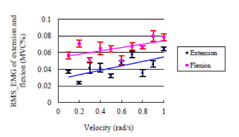
| Regarding viscous coefficient Bd, as reported by some researchers, viscous coefficient of muscle was almost unchanging, and with a small value compared with elastic modulus [17,19]. To make sure of that, a preliminary experiment was carried out by one subject, in which, the %MVC (percentage of RMS_EMG) amplitude during extension task and flexion task was measured when increasing the velocity by a step of 0.1 rad/s incrementally from 0.05 rad/s to 1 rad/s, the range was frequently applied in rehabilitation device [27]. For each step, 3 sets were done. Then, the average RMS_EMG of 3 sets for each step was calculated. The results show that % MVC was increasing monotonically with a small gradient for both extension (<0.03) and flexion (<0.02), and the value of % MVC is also small (0.02 to 0.08), as shown in Figure 3. In other words, it is reasonable to set a fixed value for the viscous coefficient, and focus on the relationship between EMG and desired elastic modulus (Kd) during extension task and flexion task in knee joint. To quantify the relationship between EMG and desired elastic modulus (Kd), the static synthetic impedance of knee joint and swing arm was identified firstly using least squares method (sub-section B of this section), and the influence of static impedance of swing arm and lower limb, friction effects, and viscous coefficient were compensated as Equation (3). Then, a set of different values were set for Kd. For each Kd value, knee extension and flexion experiment (Experiment-1, as described by the next sub-section) was done, and EMG signals for a pair of antagonist muscle were recorded and calculated as denoted by sub-section C. Thus, a set of Kd-EMG data could be collected, and through curve fitting (Equation (8)), a continuous function could be acquired. |
 (8) (8) |
| In the experiment for confirming the effectiveness of the variable impedance control (Experiment-2, as described in the following subsection), The value of desired elastic modulus Kd could be calculated by reverse looking up the function acquired through curve fitting (Equation (8) in the last step, Experiment-1), using the EMG measured. |
 (9) (9) |
| Experiment procedure |
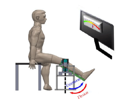
| Experiment-1: The purpose of this experiment was to investigate the relationship between EMG and parameters of changing impedance during knee joint extension task and flexion task. The experiment setup could be illustrated in Figure 4. Nine subjects (three women and six men, aged from 24 to 32, Weight 50-75 Kg, and with no apparent sensory or motor impairment on lower limbs) participated in this experiment. A full explanation was made about the contents and purpose of experiment to all nine subjects, then an informed consent was signed by all subjects. During each intervention session, a sufficient rest was arranged. In this study, extension task was defined as a move from an initial angle (vertical to the ground) to an end angle (1 rad in relation to the ground), and flexion task was vice versa with the extension task. |
| To quantify the relationship between EMG and desired elastic modulus (Kd), the static synthetic impedance of knee joint and swing arm was identified firstly using least squares method (sub-section B of METHOLD), and the influence of static impedance of swing arm and lower limb, friction effects, and viscous coefficient were compensated as equation 3. Then, the value of desired elastic modulus (Kd) was incrementally increasing by a step of 10 N√?¬?m/rad from 0 N√?¬?m/rad as a negative torque. The EMG of target muscles was measured in each step. For each step, 3 sets were done. Then, the average of 3 sets for each step was calculated. All the subjects were required to track with a specified rhythm (0.1 Hz) in a sitting position as shown Figure 4. The lower limb angle and designated tracking angle were fed back to the subject through a monitor, as shown in Figure 5. θd was settled from reached angle as -0.1 radius in this study. |
| Experiment-2: The second experiment (Experiment-2) was to confirm the effectiveness of the variable impedance control with the motion-dependent models acquired in Experiment-1, and to verify whether the motion-dependent variable impedance control method could achieve a stable and robust assist movement. To confirm the effectiveness of the impedance estimation with EMG signals and the variable impedance control based on the estimation, and find a suitable control parameter considering target muscles√ʬ?¬? dynamic characteristics to make the robotic system more user-oriented in human-robot cooperative tasks. Four different control policies were tested, i.e., NA: No Assist; FO: using EMG-impedance model from the Flexion Task; EO: using EMG-impedance graph from the Extension Task; FE: using two EMG-impedance models from Flexion and Extension task correspondently.The same nine subjects as in the Experiment-1 participated in this experiment. The subjects were required to do the movement of extension and flexion reciprocally to track the desired tracking angle in the range of 0-1 radius in sitting position as shown in (Figures 4 and 5). The discrepancy between a desired and reached angle, and sum of RMS_EMG (one set) of target muscles were used to evaluate the validity of our methods. For each test, 10 sets were done. And there, the time rang of each set was 10 s (0.1 Hz). Then, the average of 10 sets for each subject was calculated. |
| Results |
| Results of experiment-1 |
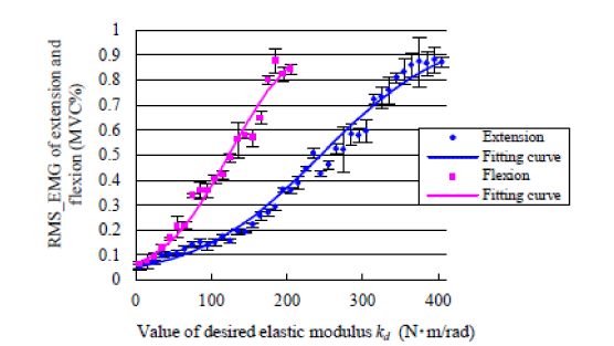
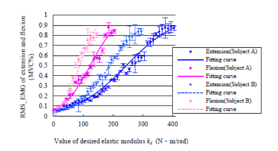
| Figure 6 shows the RMS_EMG of one subject during extension task and flexion task when increasing the desired elastic modulus incrementally. It indicates that the RMS_EMG of target muscle increases as the elastic modulus increases. The RMS_EMG of flexion task reached 80% when the value of desired elastic modulus was set to 205N√?¬?m /rad. However, contrary to the RMS_EMG of flexion task, the RMS_EMG of extension task reached about 80% when the value of desired elastic modulus was almost 405N√?¬?m /rad. That is to say, the EMG-impedance properties of the two different types of movement are asymmetric. To express this in a model, a mathematical formula could be suggested as Equation (8) in sub-section D of method section. Table 1 show that the fitting parameters of all nine subjects by equation 8 during extension task and flexion task. Figure 7 shows the RMS_EMG of two different subjects. It indicates that the RMS_EMG of the two subjects both extension task and flexion task increases as the elastic modulus increases. However, results also indicate that the value of desired elastic modulus is different for the two subjects when reaching about 80% MVC of target muscle both extension task and flexion task. Table 2 shows the value of desired elastic modulus of all nine subjects both extension task and flexion task when reaching 80% MVC. It also shows that the desired elastic modulus of extension task is bigger (p<0.01, t-test) than flexion task when reaching 80% MVC. However, the proposed model is able to approximate the relationship between the EMG and the desired elastic modulus by adjusting the fitting parameters a and b, as described in Equation (8). |
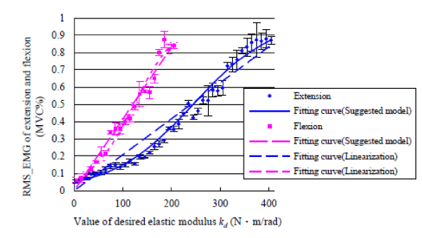
| Figure 8 shows the fitting curve by linear model and the fitting curve by proposed nonlinear model. Table 3 shows mean residual (the differential values between the real value and estimated value) of desired elastic modulus value between linear model and proposed model. Results show the mean residual of proposed model express a smaller value (p<0.01, t-test) than linear model. |
| Although the nonlinear model fits the recorded data better than the linear model, it is still possible to simplify the model by connecting several special points with the proposed model. In this way, the proposed model could be identified easily, quickly, and reasonably by some special points, i.e., the inflection points, as a medical evaluation method for paralyzed people for whom it is difficult to attend the experiments. For the inflection point of the proposed model, the first and second derivatives were expressed as follows. |
 (10) (10) |
 (11) (11) |
| Therefore, from the property of the second derivatives, to calculate the infection point of proposed model, Equation 12 could is formed as: |
 (12) (12) |
| From Equation 12, the inflection point could be calculated as bellow: |
 (13) (13) |
 (14) (14) |
| Table 4 shows an inflection point of proposed model. EMG-elastic modulus relationship could be described by an inflection point and the other two points i.e., the maximum Kd and minimum value Kd, because the proposed model has the property of bilateral symmetry. That is, the changes of EMG-desired elastic modulus relationship could be easily represented by only three points. |
| Results of experiment-2 |
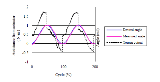
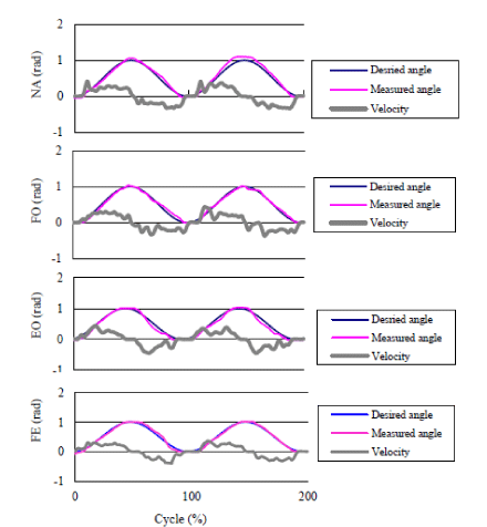
| The purpose of the second experiment (Experiment-2) was to confirm the effectiveness of the variable impedance control with the motion-dependent models acquired in Experiment-1. To verify effectiveness of different control methods, four different tests were done, i.e., NA: No Assist; FO: using EMG-impedance model from the Flexion Task; EO: using EMG-impedance graph from the Extension Task; FE: using two EMG-impedance models from Flexion and Extension task correspondently. In the FO, EO and FE, the value of desired elastic modulus was calculated from RMS_EMG as an assist torque output expressed in Equation 9. The actuator provides torque assistance in the FO, and EO, FE tests to assist the subject to track the designed tracking angle using impedance control policy. Figure 9 shows an example of two cycles of the desired angle and torque output from actuator (servo motor) by proposed variable impedance controller (FE). It indicated that actuator could provide torque assistance to track desired angle in the cooperative system. |
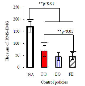
| In this experiment, the accuracy of position control, i.e., the angular error, and muscle effort needed, i.e., the sum of RMS_EMG of target muscles was used to evaluate the effectiveness of motion-dependent impedance control by comparing with the invariable impedance control method. Figures 10 and 11 shows an example of trajectories of the two angles (desired and reached angle) and RMS_EMG data of proposed impedance model by comparing with other control policies. Figures 12 and 13 shows the sum of RMS_EMG and angular error comparison of the different control policies (NA, FO, EO, FE, see the description of Experiment-1 in METHODS section), respectively. |
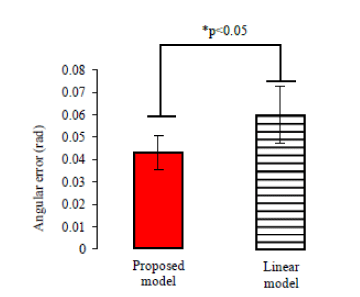
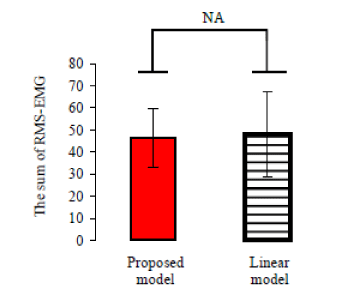
| Results indicate that there is a significant difference (p<0.01, t-test) in angular error between the FE case (i.e., the case of using motiondependent impedance models), the EO (i.e., the case of using only impedance model of extension task) and NA (i.e., no assist case). A significant difference with (p<0.01, t-test) is observed in sum of RMS_ EMG between using FE and NA, and a significant difference with (P<0.01) is also observed in sum of value of RMS_EMG between FE and FO. Results also indicate proposed nonlinear variable impedance control method (using nonlinear control parameter) could achieve a smaller discrepancy (P<0.05, t-test) than using linear variable impedance control as shown in Figure 14. However, there are no significant differences noted in sum of value of RMS_EMG between using the nonlinear variable impedance control method and using linear variable impedance control as shown in Figure 15. |
| Discussion |
| As discussed before, a number of rehabilitation robotic systems based on EMG-driven impedance control, capable of reacting to the patient√ʬ?¬?s voluntary muscle activations, have been developed for the purpose of improving motor function after stroke over the past few years. However, to develop a stable and robust active assistive, it is crucial to clarify the relationship between EMG signals and changing impedance during different tasks i.e., extension task and flexion task. |
| Experiment-1 investigated the possibility of impedance estimation from EMG signals recorded during extension and flexion in knee joint. The results showed that RMS_EMG of target muscles increases as specified elastic modulus increases, but there is a difference in property between the extension task and flexion task. However, as an experiment condition during each intervention session a sufficient rest was arranged to all subjects in this experiment. In addition, the relationship between EMG signals and changing impedance during fatigued condition was studied. Here fatigued condition was definite as those subjects were required to repeat the movement of extension and flexion reciprocally in the range of 0-1 radius in sitting position as shown in Figure 4, where a 35% of maximum resisted movement of 2~3 minutes to lower limb [27]. Figure 16 shows the relationship between % MVC and desired elastic modulus during normal and fatigued condition both extension task and flexion task when increasing desired elastic modulus incrementally. Result indicates that the % MVC shows a different feature between normal and fatigued condition when increasing the value of elastic modulus to same values. The width of % MVC became narrower at a fatigued condition compared with taking a sufficient rest for both the tasks. The changing range of flexion task is bigger than extension task. However, our proposed model could also fit that by adjusting the parameters of model as Equation (8). Figure 17 shows the % MVC and fitting curve during extension task of one subject when increasing (5~400 N√?¬?m/rad) and decreasing (400~5 N√?¬?m/rad) the desired elastic modulus gradually. Result indicates that % MVC by the condition of decreasing the desired elastic modulus gradually is bigger than the condition of increasing the desired elastic modulus gradually when reached about 80% MVC. However, the % MVC of two conditions is similar when the value of desired elastic modulus is below 200 N√?¬?m/rad, and the % MVC when increasing the desired elastic modulus is bigger than decreasing the desired elastic modulus when the value of desired elastic modulus over 200 N√?¬?m/rad. Figure 18 shows the relationship between EMG and changing elastic modulus using different move velocity from 0.1 rad/s to 0.6 rad/s. It shows that the RMS_EMG of target muscle increases as the velocity increases, but the increasing rate is different with different velocity. Therefore, the effect of velocity should be considered in a high speed rehabilitation system. Figures 16-18 shows the relationship between EMG and the changing elastic modulus in three different conditions, i.e., fatigued condition, different path of the changing elastic modulus (increasing or decreasing), and different velocity of the motion. Results show that the EMG-impedance model varies with different conditions. As shown by Experiment-2, if the parameters of impedance control models did not match users√ʬ?¬? joint stiffness, the angular error was bigger and more muscle effort was required, since the cooperative system would become unstable and difficult to control. To accurately describe the relationship between EMG and the changing impedance, it is necessary to establish condition-dependent model, by adjusting the parameters of Equation (8). The method described in sub-section D of Methods section and could be used. Nevertheless, in the next stage, the effectiveness of the condition-dependent models should be verified by further experiments. |
| Figure 19 shows the relationship between EMG and elastic modulus by using different initial position. It shows that the RMS_EMG of target muscle increases as the elastic modulus increases, but the increasing rate is different with different initial positions. It shows that the elastic modulus could be different in different initial angle of lower limb. This result could be predicted by neurophysiologic property of muscle. However this would not be an obstacle of applying the impedance estimation to variable controller, since a fixed initial and final position could be chosen. The purpose of the second experiment was to verify the effectiveness of the impedance estimation and variable impedance control based on the EMG signals. There is a significant difference (p<0.01, t-test) in angular error between the case of estimating impedance using two separated properties, and the case of using only the property of extension task and no assist case. A difference with (p<0.01, t-test) is observed in sum value of RMS_EMG between using the separated properties and no assist case, and a difference with (P<0.05, t-test) is also observed in sum of value of RMS_EMG between using the separated properties and using EMG-impedance graph from the extension task. It indicates that the proposed impedance control method could offer a durable and required less muscle effort compared with other methods. On the other hand, the cooperative system is unstable when improper control parameters were adopted. Therefore, in order to use EMG signals to control rehabilitation robotic system more user-friendly, the calculated method of RMS_EMG, for example the integration interval and sample frequency have or not affect the result of control system should to investigate. Therefore, in the next stage, we should focus on how the RMS_EMG of integration interval and sample frequency influences the control system by using more subjects. Moreover, to subjects of the hemiplegic, how to use the relationship between EMG signals and changing impedance of healthy side to control the paralysis, that the effectiveness should be investigated in next stage. |
| Conclusion |
| In this study, two experiments were performed to investigate the variable impedance control based on a model of impedance estimation with EMG signals for a lower limb rehabilitation robotic system. The first experiment was to study the relationship between EMG signals and value of desired elastic modulus. Based on the experiment results, a nonlinear and motion-dependent model was proposed. The second experiment was to verify the effectiveness of the variable impedance control with the impedance estimation model acquired in Experiment-1. The achievements obtained in this study are summarized below: |
| 1) A nonlinear and motion-dependent model could represent the relationship between EMG and changing impedance, resulting in a smaller mean residual (the differential values between the real value and estimated value) than the linear model. |
| 2) The proposed variable impedance control method (using nonlinear control parameter) could achieve a smaller angular error and require less muscle effort in knee joint extension and flexion tasks than the invariable impedance control, and it also could achieve a smaller angular error than the motion-dependent linear variable impedance control. |
References |
|
Tables and Figures at a glance
| Table 1 | Table 2 | Table 3 | Table 4 |
Figures at a glance
 |
 |
 |
 |
 |
| Figure 1 | Figure 2 | Figure 3 | Figure 4 | Figure 5 |
 |
 |
 |
 |
 |
| Figure 6 | Figure 7 | Figure 8 | Figure 9 | Figure 10 |
 |
 |
 |
 |
 |
| Figure 11 | Figure 12 | Figure 13 | Figure 14 | Figure 15 |
 |
 |
 |
 |
| Figure 16 | Figure 17 | Figure 18 | Figure 19 |
Relevant Topics
- Electrical stimulation
- High Intensity Exercise
- Muscle Movements
- Musculoskeletal Physical Therapy
- Musculoskeletal Physiotherapy
- Neurophysiotherapy
- Neuroplasticity
- Neuropsychiatric drugs
- Physical Activity
- Physical Fitness
- Physical Medicine
- Physical Therapy
- Precision Rehabilitation
- Scapular Mobilization
- Sleep Disorders
- Sports and Physical Activity
- Sports Physical Therapy
Recommended Journals
Article Tools
Article Usage
- Total views: 14701
- [From(publication date):
October-2013 - Apr 02, 2025] - Breakdown by view type
- HTML page views : 9989
- PDF downloads : 4712
