Research Article Open Access
The Preparation of a Molybdenum Based High Temperature Refractory Alloy by Powder Processing Route
Chakraborty SP* and Krishnamurthy N
Korea Institute of Science and Technology, Seoul, South Korea
- *Corresponding Author:
- Chakraborty SP
Fusion Reactor Materials Section, Materials Group
Bhabha Atomic Research Centre, Trombay, Mumbai 400085, India
E-mail: spc@barc.gov.in
Received Date: August 29, 2013; Accepted Date: September 04, 2013; Published Date: September 11, 2013
Citation: Chakraborty and Krishnamurthy (2013) The Preparation of a Molybdenum Based High Temperature Refractory Alloy by Powder Processing Route. J Powder Metall Min 2:113. doi: 10.4172/2168-9806.1000113
Copyright: © 2013 Chakraborty and Krishnamurthy. This is an open-access article distributed under the terms of the Creative Commons Attribution License, which permits unrestricted use, distribution, and reproduction in any medium, provided the original author and source are credited.
Visit for more related articles at Journal of Powder Metallurgy & Mining
Abstract
Molybdenum-based TZC alloy having nominal composition of Mo–1.2 Ti–0.3 Zr–0.1 C (wt%) possesses several attractive features for high temperature structural applications. These include high melting point, high tensile and creep strength, high resistance to heat and corrosion, good thermal diffusivity and satisfactory welding properties. However, synthesis of TZC alloy with micro-alloying additions of Ti, Zr and C by conventional high vacuum melt-casting route is a challenging task to achieve homogeneous alloy composition in view of segregation of alloying components. Hence, in the present investigation, an alternative approach to prepare homogenous TZC alloy was adopted by a powder processing route, namely, mechanical alloying (MA) at room temperature. As, Mo is a major ingredient (~98.25%) in TZC alloy, hence, this component was prepared in the laboratory to satisfy the requirement for indigenous development of the alloy. Apart from pure elements used for the alloy preparation, carbon requirement of the alloy was fulfilled from toluene medium used during milling. MA powder that was obtained exhibited fine grained microstructure with nano sized grains available in the range of 10-20 nm having polyhedral shapes. A high rate of densification, close to theoretical density, was achieved during sintering of MA powder between the temperature ranges of 1500-1700°C. XRD analysis confirmed the formation of carbides phases and the composition of the sintered alloy nearly matched the desired alloy composition. Transmission electron microscopy (TEM) studies have revealed the uniform distribution of carbides in the MA alloy having round shapes.
Keywords
Refractory alloy; TZC; Mechanical alloying; Sintering; Carbides
Introduction
Molybdenum based refractory alloys are characterized by their extremely high melting temperature (>2000°C) and high strength which range well above those of iron, cobalt, and nickel based conventional superalloys. While superalloys loosen their strength 1200°C onwards, however, in contrast, Mo based alloys can retain strength beyond 1500°C. This unique property combined with other important features of high melting point, high tensile/creep strength, high resistance to heat and corrosion make these alloy attractive for high temperature applications. A list of various commercially important Mo based alloys has been presented in Table 1 for ready reference. Amongst them, three broad classes of molybdenum alloys as identified for commercial development are: those strengthened by reactive metal carbides, those strengthened by substitutional elements and those stabilized by a mechanically dispersed second phase. Carbide strengthened alloys namely, TZM, TZC possess important properties such as high tensile and creep strength at elevated temperature combined with high corrosion compatibility with molten metals such as Pb, Pb-Bi eutectics etc. Moreover, high thermal diffusivity of these alloys enhances their resistance to thermal shock and cracking at high temperature. This obviously makes these alloys attractive for hot working tool applications particularly as forging dies for carrying out isothermal forging of super alloy engine discs in aerospace industries. The entire tooling system and work piece are kept inside a vacuum chamber in order to avoid formation of volatile oxides of molybdenum [1]. Because of high melting point, proven fabricability, very good corrosion resistance against liquid alkali metals and excellent strength at elevated temperature, the carbide strengthened refractory alloys are considered as potential candidates as structural materials for new generation thermonuclear compact reactors [2]. Amongst the various Mo based alloys, TZC (1.2% titanium, 0.3% zirconium, 0.1% carbon) alloy has superior high temperature strength, high recrystallization temperature with good plasticity at room temperature than other varieties of Mo alloys. TZC alloy containing greater amount of minor elements (Ti, Zr and C) as compared to TZM, render a dispersed network of carbide phases of TiC and ZrC for imparting additional strength to the alloy. C apart from carbide forming, also plays the role of deoxidation, so a high strength, low oxidation properties are achieved in this category of alloys.
| Alloy | Nominal Composition, Wt% | TRecryst., °C |
|---|---|---|
| Carbide ΓΆΒ?Β?Strengthened | ||
| TZM | 0.5 Ti, 0.08Zr, 0.03C | 1400 |
| TZC | 1.2 Ti, 0.3Zr, 0.1 C | 1550 |
| MHC | 1.2 Hf, 0.05 C | 1550 |
| ZHM | 0.4 Zr, 12. Hf, 0.12C | 1650 |
| Substitutional | ||
| 25 W | 25W | 1200 |
| 30 W | 30W | 1200 |
| 5 Re | 5 Re | 1200 |
| 41 Re | 41 Re | 77771300 |
| Dispersed ΓΆΒ?Β?Phase | ||
| PSZ | 0.5 vol% ZrO2 | 1250 |
| MH | 150 ppm K, 300 ppm Si | 1800 |
| MY | 0.55 yttrium mixed oxide | 1300 |
Table 1: Commercially available molybdenum based alloys
Molybdenum-based refractory alloys are conventionally prepared by vacuum arc melting technique on tonnage scale on a commercial basis and by powder processing route on a limited scale. However, in melting route, in view of high melting temperature of Mo (2650°C) and its reactive nature, power intensive steps like high temperature and high vacuum are employed during arc melting to melt and synthesize the alloys. Moreover, for this kind of refractory alloy, melting process becomes quite challenging to overcome the problem of segregation of minor alloying elements in view of their insignificant quantities and large variation in the melting temperature with respect to major element. Hence, multiple melting trials are carried out to make the homogenized alloy. In some arc melting processes, an intermediate powder processing route is adopted to mix the alloying components well at room temperature in order to form homogenized consumable electrode, however, during melt consolidation by consumable arc melting technique again segregation recurs. So, overall, by following conventional melting or by a combination of powder processing and melting, it is difficult to achieve homogeneous alloy composition. As compared to the above routes, mechanical alloying (MA) is more advantageous as the entire operation of alloying is carried out at room temperature without application of any high temperature furnace or high vacuum system. In this process, repeated welding and rewelding of the elemental powders in a high energy ball mill produces a homogeneous distribution of alloying components and avoids many problems associated with melting and solidification [3].
In the present investigation, solid state powder processing by mechanical alloying technique was adopted to prepare TZC alloy. In this process, continuous milling and mixing of powder particles for prolonged duration was carried out to make homogeneous alloy at room temperature. MA powder was then fabricated into disk shapes by pressing and sintered to achieve high rate of densification. The alloy composition was evaluated by X-ray fluorescence (XRF) analysis and corresponding elemental distribution in the alloy was investigated by electron probe microanalysis (EPMA). The structural evolution during the formation of the alloy was studied by X-ray diffraction analysis (XRD) and corresponding powder morphological changes was investigated by scanning electron microscopy (SEM). The Microhardness profile across the sintered samples was evaluated and optical as well as SEM characterization of the micro-structural features of the sintered alloy was studied. Transmission electron microscopy (TEM) was used to evaluate the carbide morphology in the resultant alloy.
Experimental
Materials
The main ingredient for the preparation of TZC alloy is Mo powder as its content is more than 98 wt% and other components are of minor elements of Ti, Zr and C whose combined content is not more than 2 wt%. However, Mo powder has tendency to form oxides easily during storage. Hence, in the present investigation, Mo powder used for TZC alloy preparation was freshly prepared in the laboratory by H2 reduction of the oxide intermediates of Mo. The as-reduced active metal powders of Mo have size range of 3-10 μm, with purity 99.5%. Minor alloying components of Ti and Zr were procured from market with purity ≥ 99.9%. Carbon addition to the alloy was satisfied by way of carbon intake from liquid toluene used during mechanical alloying process.
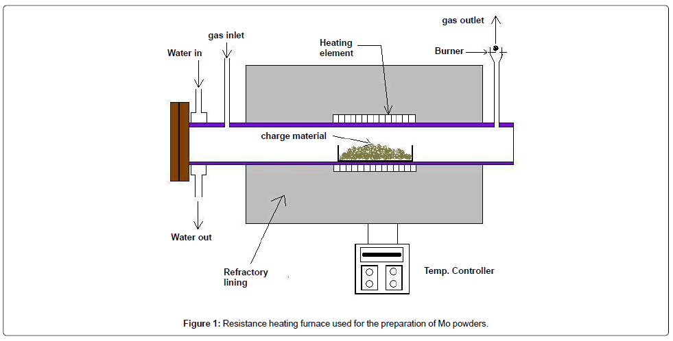
As-received high-grade molybdenite (MoS2) concentrate containing 50-53 wt% Mo value was first roasted in air at 650°C for 2-4 hrs under dynamic flow of air to convert it into MoO3. Subsequently, MoO3 was successively reduced to Mo2O5, MoO2 and Mo powders by H2 reduction at 450°C, 1100°C and 900°C respectively. The reduction process involving conversion of MoO2 into respective metal powders was carried out isothermally at the above temperatures in presence of 100% H2 in a resistance heating furnace with horizontal retort, as shown in Figure 1. The charge materials were kept in a clean Mo boat at the centre of the retort. Thermal analysis of the reduction reactions was performed by simultaneous TG-DTA analysis to evaluate the reaction temperature.
Mechanical alloying
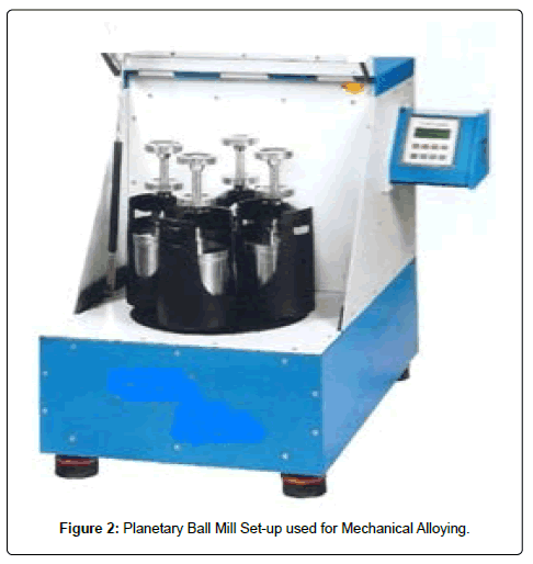
As-reduced active Mo powder obtained by hydrogen reduction was blended thoroughly with other elemental powders of Ti and Zr in the desired proportion using a Turbo-mixture. The blended powder was subsequently milled in a high energy 4 bowl planetary ball mill as shown in Figure 2 on 0.5-1 kg scale. Hard tungsten carbide balls of dia. 8 mm were used with charge to ball weight ratio as 10:1. Liquid medium of Toluene was used during milling to avoid any atmospheric contamination of Mo, Ti and Zr as these components are highly prone to oxidation. Toluene also served the purpose of carbon addition during the formation of TZC alloy. In order to evaluate the process of alloying, milling was interrupted periodically and a small amount of powder was collected for XRD analysis at every 5 hrs intervals. The vials were rotated at an angular speed of 300 rpm. The detailed experimental parameters used for performing mechanical alloying were presented in Table 2. Structural analysis of the as milled powders was carried out by X-ray diffraction technique using Cu Kα radiation (λ=1.54 Å) at a tube rating of 40 kV and 30 mA in a commercial powder X-ray diffractometer (Seifert 3003 T/T).
| Parameters | Value |
|---|---|
| Vessel volume (cm3) | 250 cc for each bowl |
| Container material | 304 stainless steel with WC lining |
| Rotor Speed | 300rpm |
| Tungsten Ball diameter | 8 mm |
| Charge ratio (mass of grinding ball : mass of powder) | 10:1 |
| Total charge | 500g ΓΆΒ?Β?1 kg |
| Medium of Grinding | Liquid Toluene |
| Milling Time (h) | 5-30 |
Table 2: Experimental parameters used for mechanical alloying
Compaction and sintering of mechanically alloyed powders
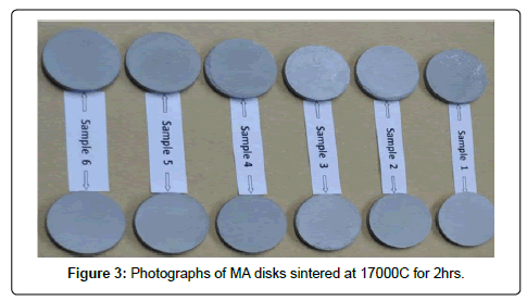
Mechanical alloyed powders were compacted at 500 MPa pressure to prepare a number of disk specimens of size, 25 mm dia. and 2 mm height by uniaxial compaction in a 25 ton capacity hydraulic press. The green compacts were then kept in refractory boats and placed inside a tubular furnace to carry out sintering operation. Sintering was performed under following cycle: (a) heated from room temperature to sintering temperature (1500-1700°C) with a heating rate of about 5°C/min. (b) kept the sintering temperature for the desired duration (1-2 hrs) (c) cooled down from the sintering temperature to 500°C and then furnace cooled from 500°C to room temperature. The sintering atmosphere was maintained under argon gas. The photo images of the MA sintered compacts were shown in Figure 3 and 4.
Mechanically alloyed TZC powder and corresponding sintered specimens after hydraulic consolidation were examined by SEM (Model No. SEM EDS Cam Scan MV 2300 CT/100) to study the powder morphology and the microstructural details of the sintered pellets. Prior to observation by SEM, sintered specimens were metallographically polished and then swab etched by an etachant prepared by dissolving 1 g of KOH and 1 g of Potassium ferrocyanide in a medium of 10 ml of H2O. Elemental mapping of Mo, Ti, Zr and C present in synthesized TZC alloy was carried out by EPMA analyzer of Model No. SX 100. Morphology of carbide particles were studied by TEM. Compositional analysis of sintered specimens was carried out by using energy dispersive X-ray spectrometer (EDS). The carbon present in the alloy was separately analyzed by Leco elemental analyzer. The densities of the sintered specimens were determined by Archimedes water immersion method. Vickers Microhardness profiles of the sintered samples were measured at different places using a Leco Microhardness tester with Model No LM 300AT. The polished and etched surfaces of the sintered samples were mounted and were subjected to optical and SEM characterization.
X-ray diffraction patterns of as- reduced Mo oxide intermediate (MoO2), Mo powder and structural analysis of the as milled powders for different duration of time was carried out by X-ray diffraction technique using Cu Kα radiation (λ=1.54 Å) at a tube rating of 40 kV and 30 mA in a commercial powder X-ray diffractometer (Seifert 3003 T/T).
Results and Discussion
Preparation of Mo powder
Conventionally, methods for the preparation of Mo powder are based on the reduction of molybdates or molybdenum oxides while the thermal decomposition of Mo(CO)6 has provided a feasible route for producing ultra- fine Mo powder on an industrial scale [4]. Molybdenite, a molybdenum sulphide compound (MoS2) is a commercially important source for molybdenum. Around 99% Mo produced worldwide is obtained from molybdenite ores. Hence, in the present investigation, attempts were made to prepare Mo powder in the laboratory from molybdenite concentrate following roasting to convert MoSi2 into MoO3 and then three stage H2 reduction of oxide intermediates of mo lybdenum. As-received high-grade molybdenite concentrate powder containing 50-53% Mo value was first roasted in air to convert it into MoO3 as per the following equation:
MoS2 +3.5O2 = MoO3 +2SO2 ....................(i)
The roasting temperature was kept at around 650°C to avoid melting of MoO3 during roasting due to its low melting point and high volatility. Table 3 has substantiated the fact about how the vapor pressure (vp) of MoO3 increases sharply with temperature and reaches to 1 atmosphere at around 1150°C. A dynamic flow of air was also maintained during roasting in order to avoid any localized overheating and also to convert any sulphurous residue present in the molybdenite concentrate into SO2. Direct reduction of MoO3 to Mo powder by H2 cannot be achieved in single stage due to high vp of MoO3 at high temperature. Therefore, reduction of MoO3 to Mo metal was performed following three-stage reductions as indicated below
| Temperature (°C) | 650 | 800 | 900 | 1000 | 1100 | 1150 |
| P (mm Hg) | 0.05 | 10.1 | 53.9 | 198.3 | 476.2 | 760.0 |
Table 3: Variation of the vapor pressure of MoO3 with temperature
2MoO3 +H2 = Mo2O5 +H2O .............(ii)
Mo2O5 +H2 = 2MoO2 +H2O .............(iii)
MoO2 +2H2 = Mo + H2O ...............(iv)
The first step of reduction was carried out at 450°C within the zone of thermodynamic feasibility as higher temperature range of 500-600°C might partially melt MoO3. The second step of reaction was carried out at 1100°C because this reaction requires more elevated temperature and lower water vapor contents in the gases. The MoO2 was then finally reduced by H2 at 900°C to prepare Mo powder in spherical shape. The controlled heating at 900-950°C range for 2-3 hrs under pure H2 gas helped to achieve >95% reduction [5].
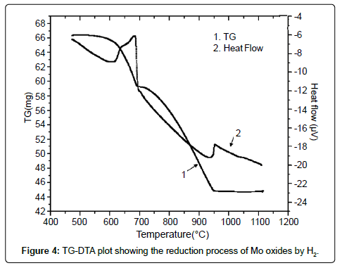
Prior to carrying out the reduction experiments, the reduction temperatures for above reactions were established by conducting simultaneous TG-DTA analysis as shown in Figure 4. It was observed from the plot that the onset of first chemical reaction (i) occurred at 600°C which subsequently culminated at 680°C. This was evident from the observation of simultaneous heat and weight loss pattern depicted by TG-DTA plot which gradually ran downward from 600°C onwards and then turned into a sharp fall at around 680°C. The second reaction started at 900°C which eventually ended at 950°C. This was also reflected in the TG-DTA plot in the form of gradual loss of weight and heat which culminated in the form of sharp fall again at 950°C and became constant then onwards. The above results were then utilized for conducting reduction experiments of MoO3 by H2 between the temperature range of 600 and 950°C.
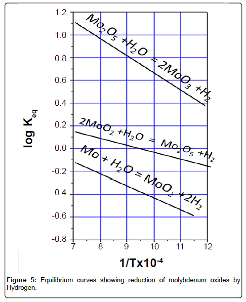
The equilibrium constant for each stage of reduction can be represented by following equation:
KP =PH2O/PH2 .......... (V)
where PH2O is the equilibrium partial pressure of water vapor; PH2 the equilibrium partial pressure of H2. As these reactions are reversible in nature, each stage of the above reactions therefore was guided by the equilibrium constant, KP. The respective equilibrium curves are shown in Figure 5. It is observed from the plot that every next stage of reduction requires a higher temperature and greater H2 content in the gas mixture. Accordingly, the experiments were conducted.
XRD analysis
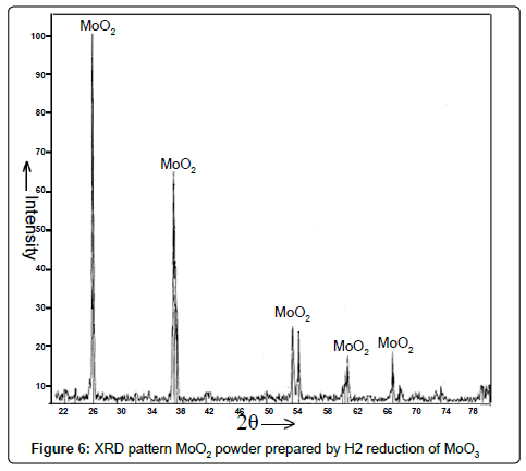
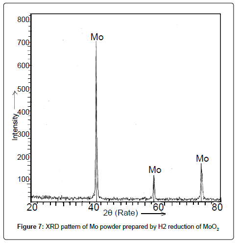
Mo oxide intermediates and Mo powder: The X-ray diffraction pattern of the as-reduced powder after first two stages of H2 reduction of Mo2O5 and MoO3 respectively revealed the formation of MoO2 as intense and sharp peaks manifested in Figure 6. The XRD pattern of powder obtained as per the chemical reaction equation no. (iv) was shown in Figure 7. It demonstrated peaks corresponding to elemental Mo confirming the formation of Mo powder after H2 reduction of MoO2.
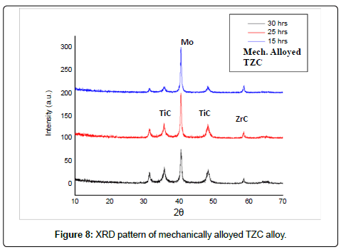
Mechanically alloyed powder mixture of TZC alloy: Figure 8 shows XRD patterns indicating the phase evolution as a function of milling time in a mechanically alloyed as-milled TZC alloy mixture. The XRD graphs exhibit altogether three well-defined peaks. Amongst these peaks, the tallest one conforms to bcc Mo and other two comparatively shorter peaks are identified as carbides of Ti and Zr. However, there were no peaks corresponding to crystalline species of elemental Ti and Zr. The gradual broadening of the reflection peaks with milling time was due to refinement of crystallite size and accumulation of lattice defects. However, there was no significant increase in peak broadening beyond 30 hours of milling. The crystallite size of the as-milled powders at different duration of time was measured from the corresponding XRD plots by using Scherrer equation,

where τ is the mean crystallite dimension, K (=0.94) is the shape factor, λ is the X-ray wavelength, typically 1.54 Å, β is the line broadening at half the maximum intensity in radians, and θ is the Bragg angle [6,7]. The average crystallite size after 30 h of milling was determined to be in the range of 10-20 nm.
Carbon analysis: Carbon content of as-milled powder for different duration of time was determined by means of a LECO Carbon analyzer. The milled samples were analyzed for their carbon content and the results were plotted in Figure 9. It was observed that the C content in the milled powder increased gradually with increase in duration of milling time. This can be attributed to C pick-up from Toluene used as a liquid medium during mechanical alloying. C concentration in the resultant TZC alloy after 30 hrs of milling was consistent with the requirement of C (~0.1 wt%) for the alloy formation. With the presumption that Toluene would be a source for carbon during the formation of TZC alloy apart from being a protective liquid medium against atmospheric contamination was a great success. Active carbon from toluene was found to be more effective in the formation of carbides as compared to physically added C in the charge mixture prior to mechanical alloying.
Compositional analysis of MA and sintered TZC alloy: Analytical technique such as energy-dispersive X-ray spectroscopy (EDS) was used for the elemental analysis of TZC alloy with respect to Mo, Ti and Zr. Carbon was already determined by earlier LECO analyzer. All results obtained by above analytical techniques and pertaining to the overall composition of sintered TZC alloy after mechanical alloying were compiled together and then presented in Table 4. The determined values of composition were found to be nearly matching with the target composition.
| Element | Weight% |
|---|---|
| Ti (K) | 1.3 |
| Mo (L) | 98.2 |
| Zr (L) | 0.4 |
| C | 0.1 |
Table 4: Composition of Sintered TZC Alloy
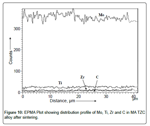
EPMA analysis: Electron probe microanalysis was performed on sintered disk of TZC alloy prepared via mechanical alloying to study the distribution of elemental components in the resultant alloy. The results of EPMA analysis were plotted in Figure 10. EPMA analysis revealed that the alloying elements such as Mo, Ti, Zr and C were uniformly distributed in the synthesized TZC alloy and consistent as per the standard composition.
Sintering studies: The relative densities and corresponding hardness values of TZC specimens sintered under various conditions were tabulated in Table 5. The densities were found to increase with increase in sintering temperature and time. Density as high as 99.86% was achieved nearly equivalent to full density. It is noteworthy to mention here that sintering temperature at 1700°C for 2 hours duration under He + 5% H2 atmosphere was adequate for achieving nearly fully dense structure of TZC alloy. Vickers micro-hardness values of TZC specimens sintered at various conditions also demonstrated an increasing trend with the increase in the sintering temperature. The increase in hardness and density can be attributed to decrease of residual porosity with the raising time and temperature of sintering.
| Sintering Specification | Sintering condition | Relative Density (%) | Microhardness (HK) |
|---|---|---|---|
| X1 | 15000C, 1 hr | 92.47 | 185 |
| X2 | 15000C, 2 hr | 93.78 | 200 |
| X3 | 16000C, 1 hr | 96.68 | 218 |
| X4 | 16000C, 2 hr | 98.79 | 230 |
| X5 | 17000C, 1 hr | 99.38 | 266 |
| X6 | 17000C, 2 hr | 99.86 | 270 |
Table 5: Relative Densities and micro-hardness values of sintered TZC specimens
SEM characterization studies
As-reduced Mo powder: SEM image showing the morphology of asreduced Mo powder obtained at 900°C after H2 reduction of MoO2 was presented in Figure 11. It reveals that very fine Mo powders were obtained after reduction having identical spherical shape and available in the size range of 5-10 μm. This kind of identical particle shape with fine size helps in the process of compaction and densification.
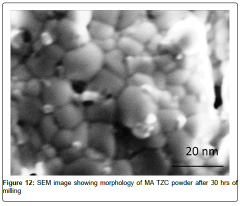
SEM characterization of TZC alloy powder: SEM image of the powder morphology of MA TZC powder after 30 hrs of milling was shown in Figure 12. The grains in the powder were found to be closely packed and assumed polyhedral shape. The particle size of powders measured by SEM during milling at various interval of time indicated significant reduction of particle size. The particles with initial size of 5 to 10 μm was drastically reduced to 10-15 nm size at the end of final stage of milling revealing a granular structure. The size of the MA powders was also substantiated by numerical analysis as per Scherrer equation (No.vi) based on XRD data inputs. However, there was not much of reduction of particle size between 20 to 30 h of milling as steady-state equilibrium was probably attained: in this situation a balance is achieved between the rate of welding and the rate of fracturing. Smaller particles are able to withstand deformation without fracturing and tend to be welded into larger particles, the overall tendency driving very fine and very large particles towards an intermediate size [6].
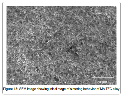
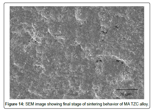
SEM characterization of sintered TZC alloy: SEM micrographs signifying sintering behavior of mechanically alloyed TZC powder at 1700°C for 2 and 4 h duration were presented in Figure13 and 14 respectively. During the initial stage of sintering as shown in Figure 13 reveals homogeneous distribution of sintering particles having less than 1 μm size. The particles are interconnected with each other leading to neck formation. The individual particles are observed to form coalescence with each other dissolving inter grain boundary between the particles by inter diffusion of particulate mass leading to nearly formation of a single matrix. At the final stage of sintering, as depicted in Figure 14, the coagulated mass forms a new grain structure with grains available from hexagonal to round shape with size varying from 1-2 μm. Finally, the sintered structure had very little porosity. The photo image of sintered pellets as shown in Figure 3 earlier also substantiated the fact that the sintered pellets were devoid of any surface cracks or surface distortion
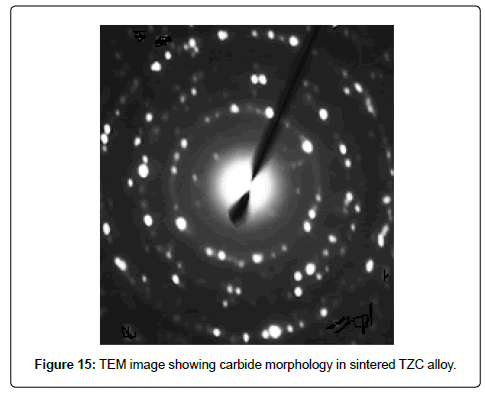
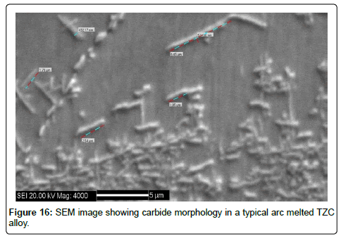
TEM characterization of carbide morphology in TZC alloy: The carbides present in TZC alloy are available in nanosize, hence to evaluate such carbide morphology transmission electron microscopy is essential. Therefore TEM study was carried out on sintered TZC alloy. TEM image showing selected area of diffraction (SAD) pattern of carbides dispersed in TZC alloy was depicted in Figure 15. The diffraction pattern shows the uniform orientation of nano particles of carbides in the form of spots around the path of some concentric circles in a microcrystalline bcc matrix of Mo. Analysis of the ring diffraction patterns showed complex carbides of Ti and Zr. The results were compared with a SEM image of carbide morphology of a typical arc melted sample as depicted in Figure 16. It shows comparatively much larger carbide particles than MA sintered TZC alloy in the shape of elongated flakes having approximately 2 to 5 μm in length and nonuniformly distributed in the form of some clusters. This obviously demonstrates that by mechanical alloying fine grained structure can be achieved in TZC alloy with nano sized carbide morphology. In another study, it was observed that the carbide particles can be grown significantly after prolonged annealing at 1200-1350°C in order to obtain desired mechanical properties.
Conclusion
Present investigation demonstrates technical feasibility of synthesis of Mo based TZC alloy of composition, Mo-1.2Ti-0.3Zr-0.25C (wt.%) from freshly prepared active Mo powder with addition of minor alloying elements of Ti and Zr by mechanical alloying technique. The requirement of C for alloying was fulfilled autogenously by active carbon transfer from Toluene used as a medium during milling. The morphological features of 30 h milled MA powder as revealed by SEM micrograph showed nano crystalline alloy powders of 10-20 nm size and of polyhedral shape. The structural evolution of the milled powder by XRD analysis confirmed the formation of TZC alloy phase via crystallite refinement. TEM study further revealed uniform distribution of nano particles of carbides of Ti and Zr having size range of 3-5 nm in the matrix of TZC alloy. Faster sintering kinetics for MA powder was observed between 1500 and 1700°C.
References
- Shields John (1995) Applications of Mo metal and its alloys: Climax speciality metals, Cleveland, Ohio.
- Dulera IV, Sinha RK (2008) High temperature reactors. Journal of Nuclear Materials 383: 183-188.
- Ahmadi E, Malekzadeh M, Sadrnezhaad SK (2011) Preparation of nano-structured high-temperature TZM alloy by mechanical alloying and sintering. Int Journal of Refractory Metals and Hard Materials 29: 141-145.
- Binghai Liu, Hongchen Gu, Qilin Chen (1999) Preparation of nanosized Mo powder by microwave plasma chemical vapor deposition method. Materials Chemistry and Physics 59: 204-209.
- Sevryukov N, Kuzmin B, Chelishchev Y (1969) General Metallurgy, Peace Publishers. Moscow, translated from Russian by B. Kuznetsov: 500-521.
- Cullity BD, Stock SR (2001) Elements of X-Ray Diffraction (3rd ed), Prentice-Hall Inc, ISBN 0-201-61091-4: 167-171.
- Jenkins R, Snyder RL (1996) Introduction to X-ray Powder Diffractometry, John Wiley& Sons Inc., ISBN 0-471-51339-3: 89-91.
Relevant Topics
- Additive Manufacturing
- Coal Mining
- Colloid Chemistry
- Composite Materials Fabrication
- Compressive Strength
- Extractive Metallurgy
- Fracture Toughness
- Geological Materials
- Hydrometallurgy
- Industrial Engineering
- Materials Chemistry
- Materials Processing and Manufacturing
- Metal Casting Technology
- Metallic Materials
- Metallurgical Engineering
- Metallurgy
- Mineral Processing
- Nanomaterial
- Resource Extraction
- Rock Mechanics
- Surface Mining
Recommended Journals
Article Tools
Article Usage
- Total views: 16343
- [From(publication date):
September-2013 - Apr 04, 2025] - Breakdown by view type
- HTML page views : 11569
- PDF downloads : 4774
