Research Article Open Access
The Impact of Distal Cantilever Extension on the Stress Around Four Implants Connected by a Bar Retained Palateless Overdenture (In Vitro Stress Analysis)
Nesreen El Sayed El Mekawy*, Ahmed Khalifa, Zylan Nyazi Baker, Pham El Quan and Wael QashoutFaculty of Dentistry, Mansoura University, El Gomhouria St, Mit Khamis WA Kafr Al Mougi, Mansoura, Dakahlia Governorate, Egypt
- *Corresponding Author:
- Nesreen El Sayed El Mekawy
Faculty of Dentistry, Mansoura University
El Gomhouria St, Mit Khamis WA Kafr Al Mougi
Mansoura, Dakahlia Governorate 35516, Egypt
Tel: 00201227884473
E-mail: nesreen_ elmekawy@yahoo.com
Received Date: May 23, 2017; Accepted Date: June 24, 2017; Published Date: June 30, 2017
Citation: EI Mekawy N, Khalifa A, Baker ZN, Quan P, Qashout W (2017) The Impact of Distal Cantilever Extension on the Stress Around Four Implants Connected by a Bar Retained Palateless Overdenture (In Vitro Stress Analysis). J Oral Hyg Health 5: 218. doi: 10.4172/2332-0702.1000218
Copyright: © 2017 Mekawy NESE, et al. This is an open-access article distributed under the terms of the Creative Commons Attribution License, which permits unrestricted use, distribution, and reproduction in any medium, provided the original author and source are credited.
Visit for more related articles at Journal of Oral Hygiene & Health
Abstract
Aim: This in vitro research was aimed to compare the impact of distal cantilever extension on the stress around four implants retained palateless overdenture by means of a bar. Materials and methods: Four implants were placed bilaterally in lateral incisor and the first premolar positions of edentulous acrylic resin maxillary model; connected bar with 7 mm distal cantilever extension with soft liner female retentive element was used. Eight strain gauges were bonded to the acrylic resin at the mesial and distal surfaces of each implant, stress was measured, then the 7 mm cantilever extension was trimmed and the stress measured for the bar without distal cantilever extension. Results: Bar with distal cantilever extension demonstrate a significant increase in stress compared to the bar without distal cantilever extension in unilateral loading and bilateral loading. During unilateral loading in bar with distal cantilever extension and bar without distal cantilever extension the maximum stress was recorded at mesial side of posterior implant of loading side. Conclusion: The four implants connected with the bar without distal cantilever extension demonstrates lower stress than bar with distal cantilever extension.
Keywords
Palate-less overdentures; Bar with posterior cantilever extension; Bar without posterior cantilever extension
Introduction
Conventional maxillary complete dentures have been created for years. It may have acceptable functions; alternative to absence of all teeth, notwithstanding comfort may be prejudicing [1]. When designing a maxillary denture, complete palatal coverage has been generally extended to near the vibration line leading to inhibition of taste [2]. Throughout life, instability is resulted from bone resorption, which demands relining of the same complete denture or construction a new one [1].
Reduction of palatal coverage gives more room for the tongue, exposes additional palatal tissue for better appreciation of food texture, [3] and provides greater comfort for complete denture wearers, especially those with hyperactive gag reflexes or maxillary tori. However, the removal of the palatal coverage reduces the area for tis sue support and diminishes the retention of the maxillary denture [4,5].
Modern osseointegrated dental implants have been dramatically improved function of any prosthesis [1]. Implants may be of primary importance in patients seeking removal of palatal coverage to maintain the necessary retention and comfort [6]. For maxilla, many prosthodontics prefer to splint the implants because of concerns about softer bone quality [7]. The bar design has advantages in terms of biomechanics, and according to Slot et al. [8] who revealed that a maxillary overdenture, supported by four dental implants, which are connected with a bar, is a successful treatment regarding survival of both the implants and overdenture.
When a bar is used, ensure proper stress distribution to bone around implants, bar height [9] and length of distal cantilever extension must be considered. Cantilevered bar-retained prostheses with distal bar extensions up to 12 mm do not negatively influence the amount of mesial and distal marginal bone around implants [10]. The impact of such biomechanical issue on relation between overdenture and their supporting implants was not clearly demonstrated especially regarding stresses around the implants in maxillary arch and the length of bar distal cantilever.
A strain gauge is a device used to measure the strain of the object. The most common type of strain gauge consists of an insulating flexible backing that supports a metallic foil pattern. The gauge is attached to the object by a suitable adhesive. As the object is deformed, the foil is deformed, causing its electrical resistance to change [11].
However, additional studies are necessary to establish guidelines regarding recommended cantilever lengths. Subsequently, this in vitro research was aimed to compare the impact of distal cantilever extension on the stress around four implants retained palateless overdenture by means of a bar.
Materials and Methods
Construction of research models
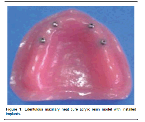
Normative Edentulous maxillary heat cure acrylic resin (Rapid simplified, Vertex-Dental B.V, The Netherlands) model with deep palatal vault was constructed from silicone rubber base impression mold (zeta plus, zhermack, Italy). Four implants fixtures (Tut (Dental Implant) Egypt) 13 mm length and 3.5 mm diameter were installed at the sites of the lateral incisor and the first premolar bilaterally in the edentulous maxillary heat cure acrylic resin model (Figure 1). The plate forms of the implants were in level with crest of the edentulous maxillary model residual ridge. The edentulous maxillary model was covered by auto polymerized silicon soft liner material (Acrostone Relining Material, England) to simulate the oral mucosa.
Construction of the bar with distal cantilever extension
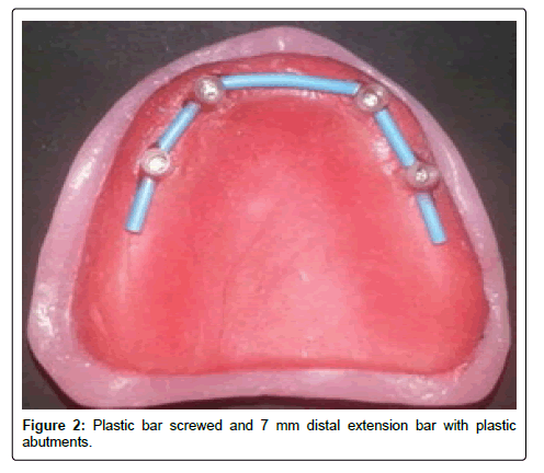
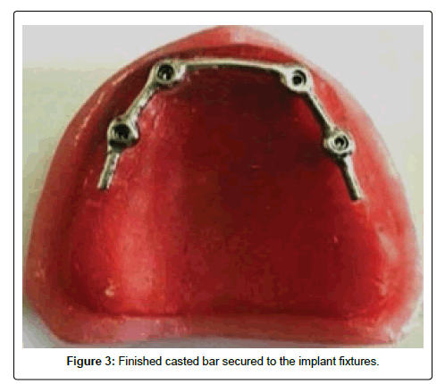
Cast-able bar abutments (Patented by: RHEN 83- Via E. Zago, 8–40128 BOLOGNA. Italy) were screwed to the implants, cut to appropriate height. The plastic bar (bredent, senden, Germany) cut to suitable length by accommodate the distance between the bar abutments, screwed to the accurate position with pattern resin. The bar was away from mucosal simulation covered the model residual ridge by 1-2 mm, cantilever distal extension of 7 mm directed along the crest of the ridge posteriorly was connected on each side of the plastic bar (Figure 2). The plastic bar pattern and bar abutments were sprued, casted, and sand blasting, finishing and, polishing. The finished casted bar was secured to the implant fixtures (Figure 3).
Fabrication of the palateless overdenture
Bar and copings on the model were covered with wax, an impression was made of the model by rubber base impression material, poured to create ten stone casts. Palatal beaded line was carved along the junction of the vertical and horizontal palatal slopes symmetrically. Construction of a record blocks according to the standard measures, anatomically setting of artificial teeth, and aluminum foil sheets of 2–3 mm thickness wrapped the bar with distal cantilever extension to create space within the intaglio surface of the overdenture for the resilient liner act as a retentive element. Flasking, packing, curing, Deflasking, finishing and, polishing of palateless overdenture were done. Remove the aluminum foil from the overdenture intaglio surface.
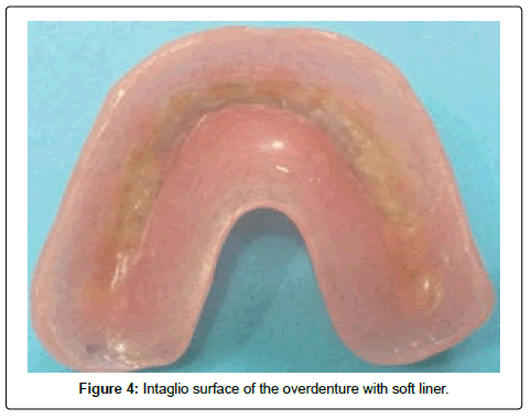
On the model; spaces under the bars were blocked out with wax, the overdenture intaglio surface was painting with soft liner adhesive and relining procedures were performed with auto polymerized addition silicone-resilient liner to produce the retentive element of the bar (Figure 4).
Installation of strain gauge
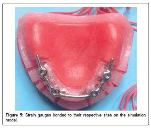
Eight linear strain gauges 1mm length, strain gauge resistance was 119.6 ± 0.4 Ω, gauge factor was 2.09 ± 1.0% and, Adaptable thermal expansion =11.7 ppm/°C, temperature coefficient of gauge factor – 0.008%/°C, with fully in capsulated grid and attached wire) were installed mesially and, distally to each implant on the model (Figure 5).
LLOYD digital loading device was used to make 60 N compressive loads in this experiment, 60 N static vertical loads was applied gradually for each time for about 10 second. Unilateral and central (bilateral) loading methods were applied. After each loading time; the strainometer measurements were recorded from all the eight gauges. Every time the experiment was under taken, the circuit was balanced and those of strain gauges, the unilateral first load for about 60 N was applied at the right first molar tooth, then the reading of the eight strain gauges was recorded at the pc, the second load (60 N) is applied at the same area and recorded again, at least 2 minutes were taken between each reading. For the central (bilateral) loading a metal bar is used to adjust the knob then 60 N is applied at the center of the denture and the reading was recorded.
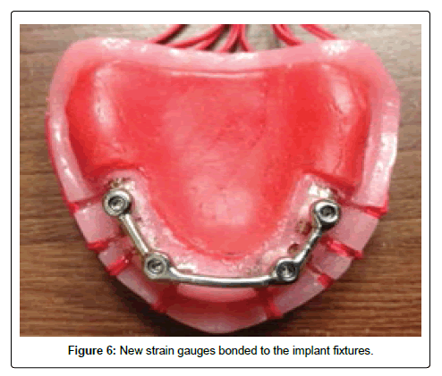
After finishing the measurement of the stress / strain on the acrylic palateless overdenture on the casted bar with cantilever extension; the posterior cantilever extension of the casted bar was cut to produce a casted bar without cantilever, the same processes of construction of the acrylic palateless overdenture were repeated to fabricate the overdenture. The eight strain gauges were changed with new gauges (Figure 6).
Statistical analysis
Results were subjected to revision and the collected data were coded, processed and analyzed through SPSS (Statistical Package for Social Sciences) (Standard version release 16.0). Descriptive statistics were applied using frequency analysis to detect mean± SD for parametric data. Independent t test for was used for comparing loading and nonloading sides in bar only and bar with cantilever constructions.
Results
Table 1 displayed t analysis test to compare the mean amounts of stresses values around anterior and posterior implants mesial and distal aspects which connected by bar with posterior cantilever extension and bar without distal cantilever extension on the loading side. It was found that the bar with distal cantilever extension produce statistical significant difference in stress applied on mesial and distal aspects of anterior and posterior implants than the bar without distal cantilever extension on the loading side.
| Loading side | Bar with cantilever (Mean±SD) | Bar without cantilever (Mean±SD) | t test |
|---|---|---|---|
| Anterior implant | |||
| Anterior Implant Mesial Side | 30.46±10.12 | 5.34±0.32 | t=6.56 P<0.001* |
| Anterior Implant Distal Side | 41.86±22.13 | 19.9 ± 0.265 | t=6.49 P<0.001* |
| Posterior implant | |||
| posterior Implant Mesial Side | 34.56±10.85 | 15.34±0.321 | t=4.68 p=0.001* |
| posterior Implant Distal Side | 27.24±2.076 | 9.63±0.623 | t=26.27 p<0.001 |
Table 1: Comparison of recorded stresses at loading side between bar with posterior cantilever extension and bar without cantilever extension.
Table 2 described t test analysis for comparison of the recorded stresses around implants connected by bar with distal cantilever extension and around implants connected with bar without distal cantilever extension during central loading. It was found that during central loading there was statistical insignificant difference between the recorded stresses around the anterior implants mesial side for both bar design with and without distal cantilever extension. While, around the anterior implants distal side and, around the posterior implants Mesial and distal side for both bar design with and without distal cantilever extension there was statistical significant difference between the recorded stresses value.
| Implant | Bar with cantilever Mean±SD | Bar without cantilever Mean±SD | t test |
|---|---|---|---|
| Anterior implants mesial side | 22.211±2.86 | 21.54±9.25 | t=0.39 p=0.703 |
| Anterior implants Distal side | 59.41 ±4.51 | 23.96±15.06 | t=6.26 p<0.001* |
| Posterior implants Mesial side | 42.93±3.37 | 20.13±3.37 | t=3.61 p=0.004* |
| Posterior implants Distal side | 27.46±2.59 | 14.59±2.59 | t=6.87 p<0.001* |
Table 2: Comparison between bar with posterior cantilever extension and bar without posterior cantilever extension at anterior implant and posterior implant during central loading.
Discussion
An implant overdenture usually subjected to different patterns of axial and non-axial forces, the eventual of these forces is transmitted through the implant overdenture and the attachments to the implants and may lead to concentration of forces in the various aspects of the implants [12]. The union of implants through a bar in an overdenture transmits more stress to the implants than in isolated systems, easing the load on the edge and providing improved support and retention [13].
This investigation results were in agreement with other studies [14,15] which found that despite the prosthetic design resultant stresses were greater on the side of the load application, and this may be due to that during the certain loading condition instability of the denture occur and cause the lifting of the contralateral side of the denture this instability was observed when the load was applied over and just distal to the implant The instability occurred at approximately 2 to 7 pounds, As the point of load application was moved distally, the load at which instability became evident increased until no denture lift was noted at a 30 pound test load applied at the first molar. In all cases anterior loads produced instability almost immediately 1 to 2 pounds.
According to Mericske-stern et al. [16] force application to the bar close to the implant and on the bar extension on the proximal location resulted in almost exclusive force transmission on to the ipsilateral implant , loading on the distal part on the bar extension led to tensile forces on the contralateral implant of 10 to 20% of the applied load., Also in unilateral loading the highest strain value was recorded at posterior peri-implant site related to cantilever design, while the lowest reading recorded at mesial peri-implant site of anterior implant of conventional bar design. This is interpreted by the magnified forces created by distal cantilever extension [17].
In the central load there is non- significant difference in anterior implant in both groups which the construction of posterior implants this gives usual for the unilateral load but expanded upon by the study for Falk et al [18]. who concluded the increase of occlusal load bone by the cantilever segment at increasing points of occlusal 70% of total biting force at 8 points of contact versus 55% of force at only four points of contacts] adding to that the concentration of the forces of the center of arch at the molar and second premolar region rather than anterior which precipitate extra stresses posteriorly [19]. Thus, to reduce forces effect on terminal implants, the occlusal forces would be oriented anteriorly rather than terminally. From other prospective, this is to array forces on the virtual quadrilateral supporting square midway with the four implants.
As a consequence, all forces applied at a distance from the implants create bending moments on the latter. Nevertheless, load application distal from the contralateral implant had no additional effect. When the posterior parts of the prostheses are loaded in the case of the bar attachments, the prostheses will rotate around the bars attachments, therefore avoiding high bending moments on the implants. The fact that the magnitudes of the axial forces are generally larger than those of the bending moments does not imply that these axial forces have a greater impact on the supporting implants and their surrounding bone.
Conclusion
Within the limitation of this study and according to the results obtained the bar with 7mm distal cantilever extension shows more stress with the two posterior implants at using four implants bar assisted palateless overdenture. While, non-cantilever extension bar shows less stresses on the peri-implant tissue in the same conditions.
References
- Kosinski T (2016) A sequential approach to implant-supported overdentures. Dent Today35:68.
- El Mekawy N, Khalifa A, Abdualgabbar E (2016) Theinfluence of palatal coverage on the retention force and fatigue resistance of mini dental implant maxillary overdenture. J Oral Hyg Health 4: 200.
- Cavallaro JS, Tarnow DP (2007)Unsplinted implants retaining maxillary overdentures with partial palatal coverage: Report of 5 consecutive cases. Int J Oral Maxillofac Implants 22:808-814.
- Ochiai KT, Williams BH,Hojo S, Nishimura R, Caputo AA (2004)Photoelastic analysis of the effect of palatal support on various implant-supported overdenture designs. J Prosthet Dent 91:421–427.
- ELsyad MA, Ghoneem NE, El-Sharkawy H Marginal bone loss around unsplinted mini-implants supporting maxillary overdentures: preliminary comparative study between partial and full palatal coverage. Quintessence Int44:45-52.
- Elsaih E (2015) Maxillary four implants retained palate-less overdenture with two arch distributions (preliminary report). Egypt Dent J61:287-297.
- Strong SM (2015) Success of unsplinted implantretained removable mandibular and maxillary over-dentures: A retrospective study of consecutive cases. Int J Periodontics Restorative Dent35:533-539.
- Slot W, Raghoebar GM, Vissink A, Huddleston Slater JJ, Meijer HJ (2010) A systematic review of implant-supported maxillary overdentures after a mean observation period of at least 1 year. J ClinPeriodontol37:98-110.
- Rismanchian M, Dakhilalian M, Bajoghli F, Ghasemi E, Sadr-Eshkevari P (2012)Implant-retained mandibular bar-supported overlay dentures: a finite element stress analysis of four different bar heights J Oral Implantol38:133-139.
- Semper W, Heberer S, Nelson K (2010) Retrospective analysis of bar-retained dentures with cantilever extension: Marginal bone level changes around dental implants over time. IntJ Oral Maxillofac Implants 25:385-393.
- Karl M, Dickinson A, Holst S, Holst A (2009) Biomechanical methods applied in dentistry: A comparative overview of photoelastic examinations, strain gauge measurements, finite element analysis and three-dimensional deformation analysis. Eur J ProsthodontRestor Dent 17: 50-57.
- Satpathy S, Satish Babu CL, Shetty S, Raj B (2015) Stress distribution patterns of implant supported overdentures-analog versus finite element analysis: A comparative in-vitro study. J Indian ProsthodontSoc15:250-256.
- Assunção WG, Tabata LF, Barão VA, Rocha EP (2008) Comparison of stress distribution between complete denture and implant-retained overdentureV2D FEA. J Oral Rehabil 35:766Y774.
- Sadowsky SJ, Caputo AA (2004) Stress transfer of four mandibular implant overdenture cantilever designs. J Prosthet Dent92:328-336.
- White SN, Caputo AA, Anderkvist T (1994) Effect of cantilever length on stress transfer by implant-supported prostheses. J Prosthet Dent 71:493-499.
- Mericske-Stern R, Piotti M, Sirtes G (1996) 3-D in vivo force measurements on mandibular implants supporting overdentures. A comparative study. Clin Oral Implants Res7:387-396.
- Kunavisarut C, Lang LA, Stoner BR, Felton DA (2002) Finite element analysis on dental implant[ndash ]supported prostheses without passive fit. J Prosthodont11: 30-40.
- Falk H, Laurell L, Lundgren D (1989) Occlusal force pattern in dentitions with mandibular implant-supported fixed cantilever prostheses occluded with complete dentures. Int J Oral Maxillofac Implants Spring 4:55-62.
- Kim Y, Oh TJ, Misch CE, Wang H L (2004) Occlusal considerations in implant therapy: clinical guidelines with biomechanical rationale. Clin Oral Implants Res 16:26-35.
Relevant Topics
- Advanced Bleeding Gums
- Advanced Receeding Gums
- Bleeding Gums
- Children’s Oral Health
- Coronal Fracture
- Dental Anestheia and Sedation
- Dental Plaque
- Dental Radiology
- Dentistry and Diabetes
- Fluoride Treatments
- Gum Cancer
- Gum Infection
- Occlusal Splint
- Oral and Maxillofacial Pathology
- Oral Hygiene
- Oral Hygiene Blogs
- Oral Hygiene Case Reports
- Oral Hygiene Practice
- Oral Leukoplakia
- Oral Microbiome
- Oral Rehydration
- Oral Surgery Special Issue
- Orthodontistry
- Periodontal Disease Management
- Periodontistry
- Root Canal Treatment
- Tele-Dentistry
Recommended Journals
Article Tools
Article Usage
- Total views: 5257
- [From(publication date):
July-2017 - Mar 31, 2025] - Breakdown by view type
- HTML page views : 4292
- PDF downloads : 965

