Study of Verification and Validation of Standard Welding Procedure Specifications Guidelines for API 5L X-70 Grade Line Pipe Welding
Received: 30-Oct-2017 / Accepted Date: 02-Nov-2017 / Published Date: 04-Nov-2017 DOI: 10.4172/2151-6200.1000147
Abstract
Verification and validation of welding procedure specifications for X-70 grade line pipe welding was performed as per clause 8.2, Annexure B and D of API 5L, 45th Edition to check weld integrity in its future application conditions. Hot rolled coils were imported from China, de-coiling, strip edge milling, three roller bending to from pipe, inside and outside submerged arc welding of pipe, online ultrasonic testing of weld, HAZ and pipe body, cutting at fixed random length of pipe, visual inspection of pipe, Fluoroscopic inspection of pipe, welding procedure qualification test pieces marking at weld portion of the pipe, tensile testing, guided bend testing, CVN Impact testing were performed. Detailed study was conducted to explore possible explanations and variation in mechanical properties, WPS is examined and qualified as per API 5L 45th Edition.
Keywords: Welding procedure specification; Welding procedure qualification record; Submerged arc welding; American petroleum institute; American society for testing materials; Tensile test; Guided bend test; Charpy V-notch impact test
Introduction
Welding procedure specification is a standard guideline used to perform a welding action. A WPS is designed and issued by welding engineer and is used by qualified welding operators and welders to perform welding operation so that in each weld, required mechanical properties can be achieved. In a typical WPS, essential variables material grade, voltage (tolerance of less than or equal to 7%), current (tolerance of less than or equal to 10%), welding speed (tolerance of less than or equal 10% for automatic welding), heat input (tolerance of less than or equal to10%)are given in a range while variables like type of welding process, method of welding electrode diameters, polarity, type of electrode and flux, shield gas type if any used are fixed and cannot be changed once a WPS is qualified. If these are to be changed in any case, a new welding procedure specification is to be made and welding procedure qualification (WPQR) tests have to be performed [1].
Methodology and Testing
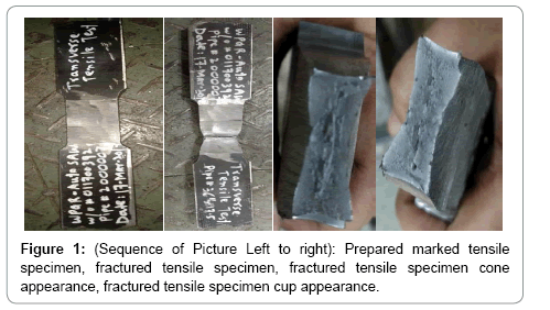
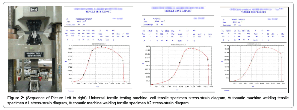
To verify mechanical properties mentioned in coil manufacturer mill test certificate, Tensile Test, CVN Impact test samples were cut from as received coil, the testing was performed as per ASTM A370 [2] standard, the testing results are presented in Table 1 which is complying with clause 9.7, 9.8 of API 5L-45th Edition. After the verification of mechanical properties, Pipe manufacturing using verified coils was done using these steps, Hot rolled coil was charged using charging lever at Spiral SAW pipe mill where first de-coiling was performed through auxiliary driver rollers, three roller leveling at 140 Bar pressure, five roller leveling at 150 Bar pressure, strip was driven further by main driver rollers at 80 Bar pressure, both edges of plate was milled as per weld geometry design given in WPS, pre-bending of plate, three roller bending at 380 Bar pressure to form pipe, inside and outside welding on pipe was performed by qualified welding operators, Online ultrasonic testing of welds, HAZ and pipe body on full length of pipe to detect defects related to weld, HAZ and pipe body, fluoroscopic examination on full length of pipe was performed to verify soundness of the weld, marking of test pieces on inspected OK pipe was done, transverse tensile testing on two specimen were performed at 25 Degree Celsius to measure ultimate tensile strength picture representation of tensile test specimen [3,4]. Tensile testing machine, stress-strain diagrams, fracture appearance of tensile test specimen after the test are shown below in Figure 1. Guided bend testing on 4 specimen (cut from weld portion in transverse direction of pipe) two face and two root was performed to bend the specimen at 180 degrees over the mandrel (the mandrel dimension was calculated as per clause 10.2.4.6 of API 5L-45th Edition and then to visually inspect for any cracks occur during bending, CVN impact testing on 9 specimen on weld area and 9 specimen on Heat affected Zone area at ambient temperature and at 0 Degree Celsius was performed to measure energy absorbed in Joules during fracture termed as toughness [5]. Testing results of specimen cut from pipe are presented in Tables 1, 2 and Figures 1-4.
| Sample | Sample Orientation | Test Piece Average Thickness (mm) | Test Piece Average Width (mm) | Gauge Length (mm) | Yield Strength (MPa) | Ultimate Tensile Strength (MPa) | Yield Ratio (Yield Ratio/UTS) | Elongation (%) | |
|---|---|---|---|---|---|---|---|---|---|
| Tensile Test | Heat No-Coil No. 1 | Transverse | 17.55 | 38.10 | 50 | 590 | 630.82 | 0.90 | 37% |
| Heat No-Coil No. 1 | Transverse | 17.52 | 38.05 | 50 | 597 | 633.67 | 0.92 | 39% | |
| Charpy V-Notch Impact Test | |||||||||
| Sample Identification | Heat No-Coil No. 1 | Specimen Size (mm) | 10 × 5 × 55 | Energy Absorbed Converted to Full Sized Specimen (Joule) | 280 | % Shear Fracture | >85 | ||
| Heat No-Coil No. 2 | 10 × 5 × 55 | 270 | >85 | ||||||
| Heat No-Coil No. 3 | 10 × 5 × 55 | 267 | >85 | ||||||
Table 1: Mechanical properties of as received coil.
| Tensile Test | Sample Identification | Sample Orientation | Test Piece Average Thickness (mm) | Test Piece Average Width (mm) | Gauge Length (mm) | Yied Strength (MPa) | Ultimate Tensile Strength (MPa) | Yield Ratio (Yield Ratio/UTS) | Elongation (%) |
| Weld 1 | Transverse | 17.58 | 38.10 | 50 | N/A | 651.82 | N/A | N/A | |
| Weld 2 | Transverse | 17.52 | 37.99 | 50 | N/A | 651.98 | N/A | N/A | |
| Charpy V-Notch Impact Test | |||||||||
| Sample Identification | Weld 1 | Specimen Size-Half Size Reduced Specimen (mm) | 10 × 5 × 55 | Energy Absorbed Converted to Full Sized Specimen (Joule) | 212 | % Shear Fracture | >85 | ||
| Weld 2 | 10 × 5 × 55 | 240 | >85 | ||||||
| Weld 3 | 10 × 5 × 55 | 224 | >85 | ||||||
| HAZ 1 | 10 × 5 × 55 | 268 | >85 | ||||||
| HAZ 2 | 10 × 5 × 55 | 252 | >85 | ||||||
| HAZ 3 | 10 × 5 × 55 | 264 | >85 | ||||||
| Guided Bend Test | |||||||||
| Sample Identification | Face Bend | Specimen Size | 300 × 50 mm | Visual Condition of specimen after bend test | No cracks and open to surfaces defects observed | ||||
| Root Bend | 300 × 50 mm | No cracks and open to surfaces defects observed | |||||||
Table 2: Mechanical Properties of welded test specimens for welding procedure qualification record.
Results and Discussion
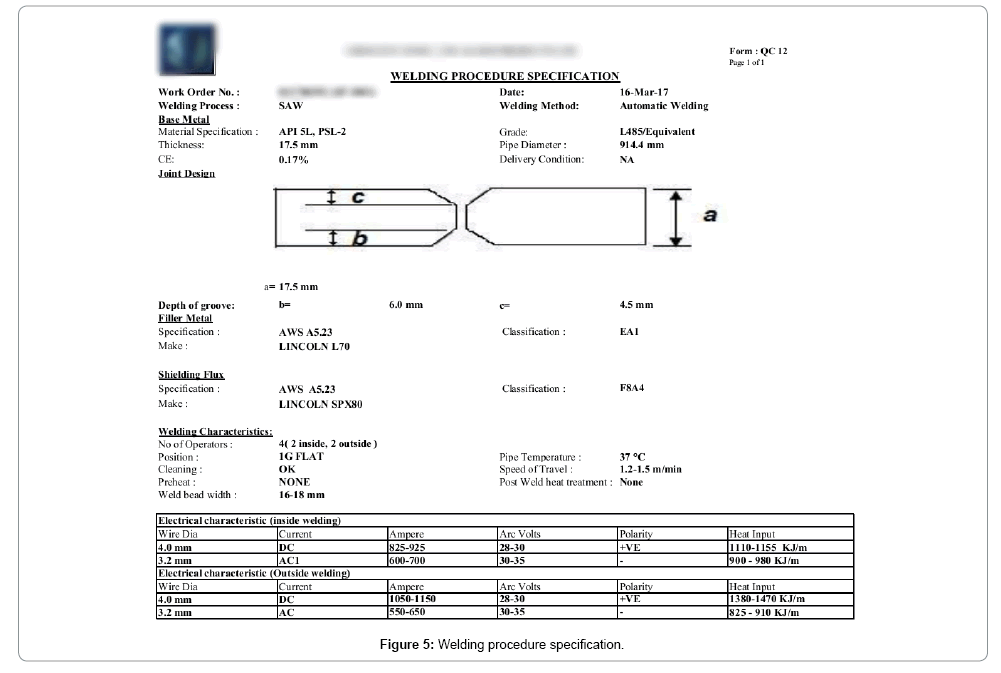
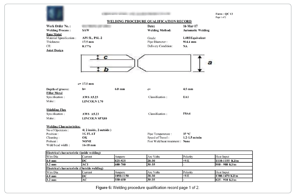
From the Table 1, it has been observed that tensile strength value of as received plate was lower as compared to the results obtained from test weld test pieces. In addition to the filling material added during welding, since welding is a thermal fusion process, material which was joined through welding had to gone though heating and cooling cycles that caused the mechanical properties of the material altered as in our case from Table 2, it can be seen tensile strength of the welded specimen has been increased [6,7]. Figure 5 shows welding procedure specification issued by welding engineer and practically used by welders in this experiment, the welding procedure qualification was done through mechanical testing and the results are shown in Table 2 the results are complying with American petroleum institute 5L-45th Edition X-70 grade line pipe weld requirements hence the WPS was validated and Quality department head approved its welding procedure qualification records like the one shown in Figures 5-7.
Conclusion
The weld metal is comparatively stronger, and the joint properties are controlled by weld metal chemical composition and microstructure. Although the welding wire is generally of a composition that matches that of the parent metal yet alloying elements are intentionally added in welding wires to improve final weldment mechanical properties major improvement in mechanical properties are observed due to the heating and cooling cycle that a material encountered during welding process thus grain structure of the material has been refined which in result increases ultimate tensile strength and impact toughness [8]. Mechanical Testing has been done against the welding joint made as per welding procedure specification, the results are complying with American Petroleum Institute requirement for weld joint of X-70 grade line pipe PSL 2 clause 9.7 and 9.8 of API 5L 45th Edition), Welding procedure specification has been validated by Quality Control department and permission to proceed has been given to the production department to continue welding practice as per approved welding procedure specification.
References
- ASTM A370 - Standard Test Methods and Definitions for Mechanical Testing of Steel Products.
- Kenneth W. Coryell (2001) The Professional's Advisor on WPS/PQR Cross Reference Tables. American Welding Society.
- Kikani P, Shah S (2015) Comparison Of WPS and PQR For Pressure Vessel Welding.
Citation: Qazi HAA (2017) Study of Verification and Validation of Standard Welding Procedure Specifications Guidelines for API 5L X-70 Grade Line Pipe Welding. Oil Gas Res 3: 147. DOI: 10.4172/2151-6200.1000147
Copyright: © 2017 Qazi HAA. This is an open-access article distributed under the terms of the Creative Commons Attribution License, which permits unrestricted use, distribution, and reproduction in any medium, provided the original author and source are credited.
Share This Article
Recommended Journals
Open Access Journals
Article Tools
Article Usage
- Total views: 6430
- [From(publication date): 0-2017 - Feb 22, 2025]
- Breakdown by view type
- HTML page views: 5630
- PDF downloads: 800
