Solar Reflective Covers on Water Reservoirs Suitable for Global Subsidies
Received: 05-Sep-2023 / Manuscript No. jescc-23-113372 / Editor assigned: 07-Sep-2023 / PreQC No. jescc-23-113372 (PQ) / Reviewed: 21-Sep-2023 / QC No. jescc-23-113372 / Revised: 25-Sep-2023 / Manuscript No. jescc-23-113372 (R) / Accepted Date: 28-Sep-2023 / Published Date: 29-Sep-2023 DOI: 10.4172/2157-7617.1000723
Abstract
Reservoir covers reduce evaporation, concentration of salt and organic growth. If such covers are designed to reflect solar energy to space, subsidies to deploy them may be available. Water reflects a small fraction of incident solar energy and places where the sun is intense with few clouds offer a high potential for reflecting solar energy to space. Satellite data can be used to compute additional megawatts reflected to space from a reflective reservoir cover so that verified planetary cooling credits can be sold, providing funding for a portion of the cost.
This article explores making solar reflective reservoir covers out of glass which would allow the covers to eventually disintegrate into sand when their useful lives are over. For covers in the form of rafts of flexibly connected large tiles made of glass, a specific design is proposed for tile shapes, connecting the tiles together, and connecting them to anchors.
Keywords: Solar radiation modification; Reservoir covers; Evaporation reduction
Keywords
Solar radiation modification; Reservoir covers; Evaporation reduction
Introduction
Reservoir covers can improve reservoir efficiency and reduce global warming
Reservoirs and canals in hot, dry regions suffer water loss due to evaporation. Evaporation increases salt concentration which reduces crop yields. Sunlight increases maintenance required due to organic growth. For example, the Lake Nasser reservoir on the Nile River in southern Egypt that regulates water supply for nearly all the irrigation in Egypt is surrounded by desert where solar energy is high. The reservoir has 6500 square kilometres of surface area. The problem of evaporation is worsened by annual timing. Evaporation is highest in summer, 11 mm per day, and this is when agricultural needs are highest [1].
At Lake Nasser, solar energy is plentiful for manufacturing and maintaining covers without using fossil fuels. Because it is in the tropics and has few clouds, the number of watts per square meter that would be reflected to space by a perfect Lambertian reflector is 190. Common, mass-produced solar reflective polymer materials having a thickness of .31mm achieve a solar reflectivity of 0.92 while transmitting 4.9%. If the polymer material is made thicker, the transmission is lower and the reflectivity is higher. The average annual albedo of deep water in the tropics is 0.05. If the reservoir covers can maintain an average albedo of 0.85, the gain will be (0.8 x 190=) 152 watts of solar energy reflected to space per square meter of cover surface. If the top surface of the cover has thermal infrared emissivity of typical polymer or glass, any reduction in radioactive cooling at night will be small compared to the reduced heat gain during the day [2].
Verifying effectiveness of reflective covers and selling cooling credits
At least one company is deploying solar reflectivity interventions to cool the planet and sell Cooling Credits to fund the effort. Smoliak et al. (2022) showed that, for any location within about 60 degrees of the equator, the potential amount of sunlight that could theoretically be reflected by the surface back to space by a Lambertian reflector from can be estimated using radioactive fluxes from reanalysis of satellite data products. Bonafoni and Sekertekin (2020) demonstrated that, within about 60 degrees of the equator, albedo (solar reflectivity) of surfaces with a minimum dimension of about 30 meters can be determined with accuracy better than 2% using data from Sentinel-2 multi-spectral satellite imagery provided by the European Space Agency. For each reservoir cover with a minimum dimension of at least 40 meters, these data can be used to compute the additional number of megawatts reflected to space by adding a reflective cover. This computation can be the basis for selling verified Cooling Credits [3].
Prior reservoir covers
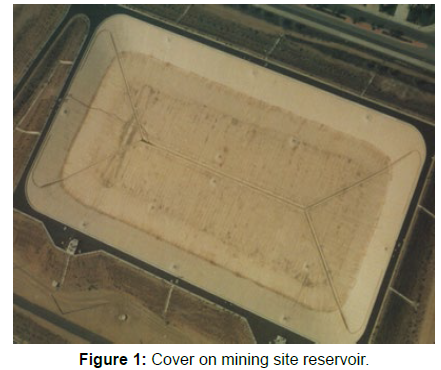
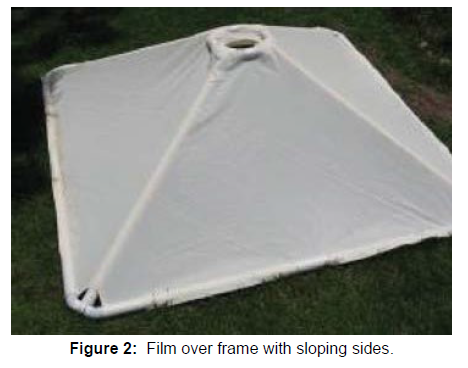
As shown in Figure 1, many floating water covers are simply a layer of limp plastic film that does not shed dust, which quickly degrades reflectivity. As shown in Figure 2, covers made with sloped tiles will shed dust with sufficient rain. In areas with insignificant rain like Lake Nasser, sloped tiles can be fitted with water splashers [4].
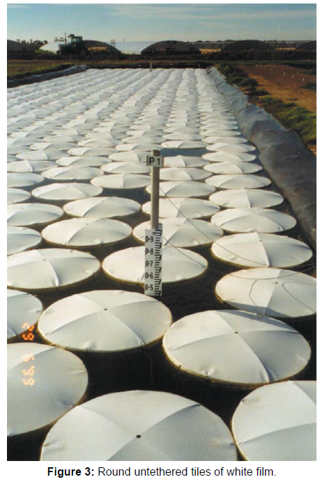
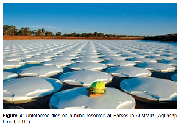
Figure 3 shows round tiles deployed in Australia in the 1990s by Burston. These tiles are not connected to each other or to a tether and they move with the wind. Figure 4 shows similar tiles of moulded polymer.
The prior floating water covers are used only for up to medium size reservoirs because they are not strong enough to withstand strong wind with a long fetch causing large waves. This article proposes development of reflective water covers in the form of rafts that can withstand strong wind, can include a device to wash off dust, and can be used on any reservoir of any size and on wastewater treatment lagoons. On reservoirs with boat traffic after dark, such as Lake Nasser, the rafts would be marked with solar powered lights and radar reflectors [5].
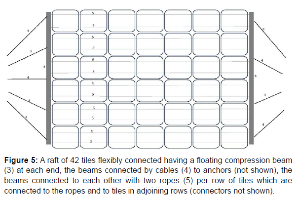
Long rafts of flexibly connected large floating tiles (Figure 5)
Figure 5: A raft of 42 tiles flexibly connected having a floating compression beam (3) at each end, the beams connected by cables (4) to anchors (not shown), the beams connected to each other with two ropes (5) per row of tiles which are connected to the ropes and to tiles in adjoining rows (connectors not shown).
Tiles with flexible joints
The least environmentally hazardous design will likely use a structure made of glass. Alternatively, at least for early prototypes, the tiles may be made of polymer. There is no present guidance on how large the tiles can be and still be strong enough, light enough, and practical to fabricate, but, in any case, they will need to have flexible joints where they connect. The flexible joint connectors can be made of wire or metal or polymer rope or hinge points. Cushions can be held between tiles. If early models are made with polymer rather than glass but glass still seems like the best long-term solution, the flexible connections for polymer tiles should be designed to predict effectiveness for future glass tiles [6-10].
Anchors and tension ropes
Reflective rafts for Lake Nasser and other large reservoirs will need to be securely anchored able against winds of about 30 knots. Each anchor should be strongly tethered to a buoy, which might also be a compression beam (3), and which applies horizontal tensile force through tension ropes (5) to the tiles. The tension ropes might be multi-strand stainless steel. As strong ropes (5) are less expensive than anchors and buoys, each raft should be as long as practical which will require strong cables (4) attached to each anchor. Long rafts can be tethered with two buoys, one at each end. At the end that faces the strongest wind, the tension cables (4) at each buoy will need to be quite strong and the tension ropes (5) will need to be as strong. If the strongest wind in the opposite direction is weaker, the cables and ropes at that end can be weaker [11].
Multiple rows joined together
Tiles can most efficiently be made with an effectively continuous web manufacturing line. Whether of glass or polymer, given current web manufacturing technology, the maximum width of early manufacturing lines will be roughly 7 meters. The optimum width for each production line will be the preferred width of the tiles that are connected to make rafts. It might turn out that optimum tile shapes are longer than wide or wider than long. Roughly 3 meters wide by 3 meters long might be a good size to try early on. As long rows of tiles come off the line, two rows can be connected together on their machine-direction sides to make a raft twice as wide as the production line. Once factory technology is developed, wide factories can be built with two or more production lines side by side [12]. Connecting two rows side-by-side can be done by light weight people gently walking on the floating tiles to make the connections. Alternatively, it can be done with an overhead boom wide enough to reach over one row to the joint or a method of working under water [13].
One compression beam at each end
Assuming the sides of the rafts do not need to be strong enough to withstand collisions with boats or rocks or other rafts, the only place where a compression member will be required (other than compressive strength within the tiles) is a lateral floating compression beam (3) at each end of the raft with strong cables (4) connecting the beam to the anchor. If the tiles are 3 meters wide and the raft is made of 12 rows, the compression beams will each need to be 36 meters long. If each row of tiles includes two tension ropes (5) extending from one beam to the other and there are 12 rows, 24 ropes will be needed the length of the raft. The compression beams (3) must float. The top side of the beam might be made reflective like a tile [14].
If the compression beams (3) are just strong enough for their main purpose and have only enough buoyancy to float themselves and connected cables or ropes, an additional buoy will be needed between the compression beam and any underwater anchor. Otherwise, the compression beam (3) may be made buoyant enough to remain floating even when a strong wind causes strong downward pull from an underwater anchor. Such a large compression beam may be made of pipe like an elongated buoy of welded metal or polymer pipe or pulltruded fibre-reinforced polymer [15].
If low strength compression beams are used, wood may be used to make the beams, such as round spars or square timbers made with glue lamination. As the wood will be in water for most of its life, it should be pressure treated with preservative. The lowest cost treated 4x4s are about $2US per foot. The beams may be made with polymers or wood-polymer composite or fiberglass-polymer composite with a core of foam or wood or hollow balls to always float. At retail, 4” PVC drain pipe is $1.50US per foot. Foam at $1US per foot can be inserted to keep it floating if it leaks [16].
Tiles
Each tile should have at least one smooth, sloped-surface pyramid on its top side so that rain or splashed water will wash away dust into gaps or openings beside each pyramid. The surface may be formed with a material that allows very low adhesion by dust and repels water to help it carry away any dust. The pyramids on each tile may be few, perhaps only one, or many and small [17].
For optimal coverage of the water surface to prevent evaporation and for optimal reflectivity, each tile should be shaped such that the waterline is at or below the periphery and the top side is high enough above the water line that it does not grow biomass. Consequently, each tile should have vertical or near vertical sides at the waterline.
Polymer tiles can be made highly solar reflective (white or aluminium coated) while quite light weight and modest cost. Where there is adequate assurance that the polymer tiles will not escape into the environment and can be retrieved and recycled before they fall apart and release micro plastics, tiles of a UV stabilized polymer such as PVC may be most cost-effective. The polymer can be formed into hollow or foam-filled tiles by blow moulding or roto moulding or attaching together parts that have been injection moulded or thermovacuum formed, in which case they can be made of expanded PVC with a density lower than water which will cause any broken parts of tiles to float to shore where they can be collected [18].
The top sides of the tiles can be moulded. For the first prototypes, blow moulding a polymer will be too expensive (tooling cost is 6-10x the roto moulding tooling). Making or attaching eyes along the edges is problematic for 2D vacuum forming of the entire tile, but eyes can be cut in a thick sheet of foam to which one or more vacuum-formed pyramids are glued.
Tiles made of glass
To avoid risk of pollution or to reduce cost or both, the tiles may be made of non-toxic, non-polymer materials that are benign if they escape into the environment such as glass or ceramic. Floating glass tiles can be made reflective on the top surface in three ways: (1) hollow, glass tiles with a clear top surface coated on the inside with metal such as silver, aluminium, or tin, or with a white paint, or (2) tiles with a surface of glass foam with micron sized bubbles that are highly reflective by Mie scattering, or (3) tiles made of glass bubbles of any size coupled to a highly reflective top surface. Glass can be made from sand and formed into foam or hollow tiles using fossil-fuel-free electric power [19].
The ultimate design of tiles may have a thin top layer that is highly reflective supported by a thick layer of glass bubbles of any color and any bubble size, even up to one meter average bubble diameter. If the top layer material is expensive, it can be made white for Mie scattering as thin as 0.31 mm and still achieve an albedo of 0.92. Glossy smooth moulds for forming tiles can be as wide as the production line, perhaps 3 meters, and as a long as one tile in the machine direction, perhaps 3 meters.
The moulds can form the tiles upside down, with pyramids pointing down. A thin layer of tacky powder or liquid that cures to be highly reflective can first be sprayed or extruded into each mould. The liquid might include glass micro-spheres or titanium dioxide or zinc oxide or barium sulphate in a liquid binder such as lime glass, waterglass (sodium silicate), epoxy, or acrylic. Each mould can then be filled with hot molten glass spheres to give the tiles a desired thickness and buoyancy. The spheres might be as small as one centimetre or as large as one meter average diameter. Instead of many glass spheres, a single sphere of molten glass can be blown and placed in each upside down pyramid mould. After blowing, it can be silvered or coated with white paint on the inside and then securely capped [20].
For development, one mould that can be turned over to release its tile can be used. For high production, many moulds may be most efficient for passing each tile through a cooling tunnel before demoulding. When the early test models are made and a first small scale factory is made, they should be made with a plan for a larger iteration at Lake Nasser.
For connecting tiles together, each tile may be formed with glass eyes along each edge. Alternatively, just after the glass is deposited in the mould, a grid may be laid down with wires that stick out for connecting tiles to each other both laterally and longitudinally, and the curing glass makes a strong bond with the filaments, as shown in (Figure 6). An additional layer of molten glass sheet, strip, or bubbles may be added on top of the grid to ensure it is secure. The filaments might be metal wire, perhaps welded monofilament stainless steel wire as shown in Figure 6, or polymer or glass fibre ropes if they can be made sufficiently durable [21].
If the grid is monofilament welded metal wire in a tic-tac-toe grid shape as shown in Figure 6, at the ends, the wire can be bent back on itself to form a welded eye. The eyes can be attached to each other or to a flexible tension rope which is connected to the next tile, or both. With this design, wire grids may be made in advance with two eyes along each edge, ready to drop one grid onto each mould while the glass is molten.
After cooling, as the tiles drop from the moulds turning over, they land on long, flexible tension ropes to which the leading and trailing edges of the tiles are clamped. The row of tiles thus linked together moves continuously down a ramp, out a factory opening and into the adjoining lake where rows of tiles may be connected together and a floating beam (3) attached at each end.
Clamping tiles to tension ropes
For use on reservoirs where wind can come from more than one direction, flexible tension ropes extend from the anchored beam at one end of the raft to the anchored beam at the other end and tiles are clamped to the tension ropes, with a clamp at each end of the tile. There may be a short, flexible leash of a few centimetres long between a clamp and an attachment point on an edge of the tile. The leashes allow the rope to stretch under tension without applying stress to the tiles. If a tile has two ropes passing under it, it will have four clamps. The forces from one tile on the clamps are small compared to the forces from a large number of tiles on the ropes. UV resistant polymer zip ties may be effective for attaching rows to each other. Preferably, stainless steel zip ties can be used. If the zip ties are connected to glass eyes, the zip ties can pass through and compress an elastic doughnut to prevent tiles from colliding.
Method to clean off dust in a dry climate like upper Egypt
In places where there is a strong rain at least once a year, rain can be relied on to wash dust off the tiles which have sloped top surfaces. For places where rain cannot be relied on to wash away dust, such as Lake Nasser in Egypt, a device to periodically spray the tiles with water may be cost-effective.
The top side of the raft is a grid of sloped surfaces, each sloped surface can have an associated sprayer that periodically sprays water over the sloped surface. At the bottom of each sloped surface is a gap in the raft through which water and carried dust may drain. Energy to lift water to the sprayers can come from one of:
- Solar PV cells that generate electricity which drives pumps,
- Diurnal solar heating of the tiles causing expansion of a gas which pumps water, or
- Wind pushes a moving part which causes water to wash each sloped surface.
The drains that allow water to flow must be wide enough to prevent clogs from bio-growth.
Lake Nasser gets winds over 20 mph every September to January. This is plenty of wind to operate a fan with tips that touch the water surface causing an upward and outward spray which is blown downwind. One or more of these fans may be mounted on the upwind edge of each tile to splash the entire tile surface. Rafts can be anchored to have a preferred end facing into the local strongest wind.
Present commercial method of making glass foam
Technology to make foamed glass with bubbles of 10 to 300 microns is well known and used to make inert heat insulating material such as for a concrete additive (Dennert Poraver 2001) or an insulating lower layer under road pavement to prevent frost heaves (Figure 7) (Segui et al. 2016).
To make the foam, particles of glass and particles of a chemical gas generating agent are mixed, placed in a furnace, and heated to around 800-900°C to obtain the viscoelastic state of glass. This temperature causes the chemical agent to release a gas, forming bubbles in the glass, and the mixture is then formed into a desired shape and cooled. Using current manufacturing methods, the resulting foam density (relative to pure water) ranges from 0.3 to 0.9.
Reflective layer made by aggregation of glass spheres
Technology has been known for more than 50 years for making individual glass microspheres (a/k/a bubbles or micro-balloons) with a density (relative to pure water) ranging from 0.1 to 0.6. A reflective top layer for the tiles may be made by sintering the bubbles at a temperature high enough to make the glass tacky or by gluing together such microspheres to make a layer of syntactic foam. The glue might be hot glass with a lower melting temperature than the bubbles or liquid sodium silicate glass (water glass) with an extremely slow rate of dissolution in water.
Discussion
In the Consolidated Appropriations Act of 2022, the US Congress directed the executive branch to develop a five-year “scientific assessment of solar and other rapid climate interventions in the context of near-term climate risks and hazards.” Based on a National Academies solar geo-engineering research and governance recommendation report, the marketplace of ideas for solar radiation modification proposals has been focused on stratospheric aerosol injection, marine cloud brightening, and cirrus cloud thinning. While the number of feasible reflectivity interventions that might achieve a scale equal to the present energy imbalance is limited, other interventions that achieve net benefits appropriate to their cost, regardless of scale potential, should also be investigated.
Examples of tested and effective reflectivity interventions with limited scale are light colored roofs and roads which are commercially available and deployed in cities to lower the temperature of urban heat islands. While they are effective for local and regional cooling and make a small contribution to reducing Earth’s energy imbalance, they cannot be scaled to solve global warming. Irvine et al. (2011) explored the climate impacts of three land surface albedo modification scenarios (urban, desert, and croplands). Kravitz et al. (2018) performed climate model simulations using idealized representations of solar radiation modification alongside CO2 quadrupling, including one that raised ocean albedo only. These studies suggest that multiple types of reflectivity interventions might prove optimal.
Solar reflective reservoir covers are a possible reflectivity intervention to modify Earth’s surface albedo so that its energy imbalance is reduced. When combined with local benefits of reduced water loss, lower salinity, and less bio-growth, the added benefits of reducing global warming may render reflective reservoir covers costeffective. To fund building of the covers, Reflection Cooling Credits might be sold based on verification of effectiveness using satellite image data and data on potential watts per square meter that could be reflected.
Conclusion
As the Earth gets warmer and consequent damages increase, it will become cost-effective to reduce solar gain by more and more methods of increasing albedo of the Earth. Of the promising methods, in watts reflected to space per dollar spent, stratospheric aerosol injection (SAI) appears likely most cost effective. However, on the chance that SAI might cause unacceptable harms, it is prudent to research other, less problematic possible methods. A method that should be researched is solar reflective reservoir covers. To avoid risk of environmental harm from micro plastics when the useful life of each cover is over, the covers might be made of glass.
Research is needed by manufacturing experts to create alternative designs and estimate costs to manufacture, identify locations where materials can be obtained at low cost, and estimate amount of electric power needed for a full-scale factory. Research is needed by fossilfuel- free electric generation experts to estimate costs of providing needed power. Research is needed by materials experts to select an optimal top layer for reflectivity and durability. Research is needed by bio-foul experts on suitable methods of preventing bio-foul or dust discoloration on top and preventing bio-foul from adding so much weight that floating covers sink.
References
- Bonafoni S, Sekertekin A (2020) Albedo Retrieval from Sentinel-2 by New Narrow-to-Broadband Conversion Coefficients. IEEE Geoscience and Remote Sensing Letters 17(9): 1618-1622.
- Burston IA, Akbarzadeh A (1999) Conservation of water from open storages by minimizing evaporation. NPIRD Final Rep. No. RM15
- Cogley JG (1979) The Albedo of Water as a Function of Latitude. Monthly Weather Review 107(6): 775-781.
- Dennert Poraver GmbH (2001) https://poraver.com/us/poraver/
- Diamond MS, Wanser K, Boucher O (2023) “Cooling credits” are not a viable climate solution. Climatic Change 176 (7): 96.
- Edmonds I, Smith G (2011) Surface reflectance and conversion efficiency dependence of technologies for mitigating global warming. Renew Energy 36 (5):1343–1351.
- Felgenhauer T, Horton J, Keith D (2022) Solar geoengineering research on the US policy agenda: when might its time come? Environmental Politics 31(3): 498-518.
- Haley J (2021) Shade Fabrics for Cooling Cities and Reducing Global Warming. J Earth Sci Clim Change 12 (9): 578.
- Haley J, Nicklas J (2021) Damping Storms, Reducing Warming, and Capturing Carbon with Floating, Alkalizing, Reflective Glass Tiles. London Journal of Research in Science: Natural and Formal (LJRS) 21: 11-20.
- Irvine PJ, Ridgwell A, Lunt DJ (2011) Climatic effects of surface albedo geoengineering. J Geophys Res 116 (D24):112.
- Koopman M, Gouadec G, Carlisle K, Chawla KK, Gladysz G (2004) Compression testing of hollow microspheres (microballoons) to obtain mechanical properties. Scripta Materialia 50(5): 593-596.
- Kravitz B, Rasch PJ, Wang H, Robock A, Gabriel C, et al. (2018) The climate effects of increasing ocean albedo: an idealized representation of solar geoengineering. Atmospheric Chemistry and Physics 18(17): 13097-13113.
- National Academies of Sciences, Engineering, and Medicine (2021) Reflecting Sunlight: Recommendations for Solar Geoengineering Research and Research Governance. Washington, DC: The National Academies Press.
- Ramadin Y, Abdallah MAH, Ahmad M, Zihlif A, Al-Ani SKJ, et al. (1996) Optical properties of epoxy-glass microballoons composite. Optical materials 5(1-2): 69-73.
- Scarinci G, Brusatin G, Bernardo E (2005) Glass Foams.
- Segui P, Doré G, Bilodeau JP, Morasse S (2016) Innovative materials for road insulation in cold climates: Foam glass aggregates. NASEM Transportation Research Board pp. 22-28.
- Smoliak B, Gelobter M, Haley J (2022) Mapping potential surface contributions to reflected solar radiation. Environ Res Commun 4(6): 065003.
- Webster MA, Warren SG (2022) Regional geoengineering using tiny glass bubbles would accelerate the loss of Arctic sea ice. Earth's Future 10(10): e2022EF002815.
- Whittington D, Guariso G (1983) Water management models in practice: a case study of the Aswan High Dam, Development in environmental modeling, 2 Elsevier, Amsterdam.
- Zhang J, Zhang K, Liu J, Ban-Weiss G (2016) Revisiting the climate impacts of cool roofs around the globe using an Earth system model. Environ Res Lett 11(8): 084014 .
- 3M Corp (2007) 3M™ Glass Bubbles K Series S Series.
Indexed at, Google Scholar, Crossref
Indexed at, Google Scholar, Crossref
Indexed at, Google Scholar, Crossref
Indexed at, Google Scholar, Crossref
Indexed at, Google Scholar, Crossref
Indexed at, Google Scholar, Crossref
Indexed at, Google Scholar, Crossref
Indexed at, Google Scholar, Crossref
Indexed at, Google Scholar, Crossref
Indexed at, Google Scholar, Crossref
Indexed at, Google Scholar, Crossref
Indexed at, Google Scholar, Crossref
Indexed at, Google Scholar, Crossref
Indexed at, Google Scholar, Crossref
Citation: Haley JT, Smoliak BV (2023) Solar Reflective Covers on Water Reservoirs Suitable for Global Subsidies. J Earth Sci Clim Change, 14: 723. DOI: 10.4172/2157-7617.1000723
Copyright: © 2023 Haley JT, et al. This is an open-access article distributed under the terms of the Creative Commons Attribution License, which permits unrestricted use, distribution, and reproduction in any medium, provided the original author and source are credited.
Share This Article
Recommended Journals
Open Access Journals
Article Tools
Article Usage
- Total views: 769
- [From(publication date): 0-2023 - Apr 02, 2025]
- Breakdown by view type
- HTML page views: 561
- PDF downloads: 208

