Self Sustained Renewable Energy Generator
Received: 24-Jan-2018 / Accepted Date: 05-Feb-2018 / Published Date: 10-Feb-2018 DOI: 10.4172/2576-1463.1000184
Abstract
Describes a method for self sustained generation of renewable energy by use of a piezo electric crystal actuator. Piezo electric crystal generates rather minute amounts of energy when deformed by force. The usable energy obtained by such actuation varies based on crystal size, applied force, but for an average size and for moderate applied force, could be about 90 micro joules. In order to collect reasonable energy for practically viable application, tens of millions of such actuation needs to be performed each second on a continuous basis.
Safely assuming only about 60 micro-joules energy for power output calculations, about ten million actuation per second will produce 600 joules of energy per second. The actuator consumes power, and achieves selfsustenance when the electrical energy produced by the actuator exceeds its own consumption requirements. As per calculations shown in detail section, it exceeds this threshold comfortably at twenty million actuations per second. The actuator is theoretically shown to be capable of over hundred million actuations per second, making available about 5K watts of excess energy for export, For a ten-fold power output increase, it can be safely observed that the actuator drive input energy demand increase is limited to less than threefold. Unlike most other forms of energy generation, where input energy is the motive energy, and the maximum output cannot exceed input energy minus all losses, here the input energy serves to subject the crystals to the motive force, and therefore does not share the same input-output relationship, and therefore makes possible its self-sustenance, a concept considered impossible in reality. As this is against the present accepted norms of science, the model and calculations are published, for a broader expert review and assessment to identify its viability.
Keywords: Renewable energy; Piezoelectric crystal actuator
Detailed Design
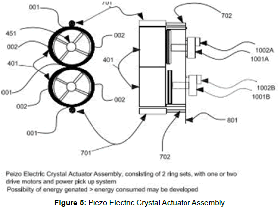
The self-sustained renewable energy generator consists of a piezoelectric crystal actuator, with 2 wheels as shown in Figure 5, driven by one or two variable speed motor. Both of the wheels consist of many rings, one within other and between each of these rings, along its width on upper face are firmly placed many piezoelectric crystals, actuation of which results in energy generation.
For purpose of example we have considered a standard available piezoelectric crystal size of 8 mm diameter and 1 mm thick. So on a ring of width 225 mm and diameter 550 mm it is possible to place over 4000 such crystals in space between two rings. The higher the diameter the more crystals it can hold.
When these wheels are compressed against each other, and by the rollers at opposite ends, the wheels deform to take an elliptical shape. When these wheels complete a full rotation, it subjects each crystal sandwiched within the ring-set, to experience two compression and two elongations. Depending upon the number of piezo crystals and number of rotation per second, the power in wattage is generated, which is collected by slip ring or other mean of collection [1-10].
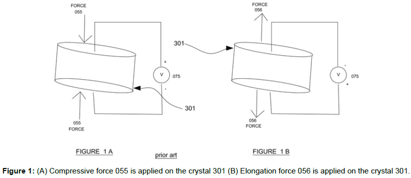
Figure 1
In Figure 1A a compressive force 055 is applied on the crystal 301, resulting in a positive potential as shown in voltmeter 075.
In Figure 1B an elongation force 056 is applied on the crystal 301, resulting in a negative potential as shown in voltmeter 075.
Figure 2
Figure 2A shows a set of rings 401, with 16 rings one within the other, having a width of 225 mm and thickness 0.5 mm. The outermost ring is 401A, within that is 401B followed by 401C, till the sixteenth and last one being 401P. Each ring is constructed of material with certain tension, resulting in the ring trying to regain its original shape if and when deformed. Each inner ring has a diameter 4 mm less that the outer ring, resulting in innermost ring 401P with diameter of 550 mm and outer ring 401A with a diameter of 610 mm. The arrangement results in a gap of 2 mm between two rings at any point under normal conditions.
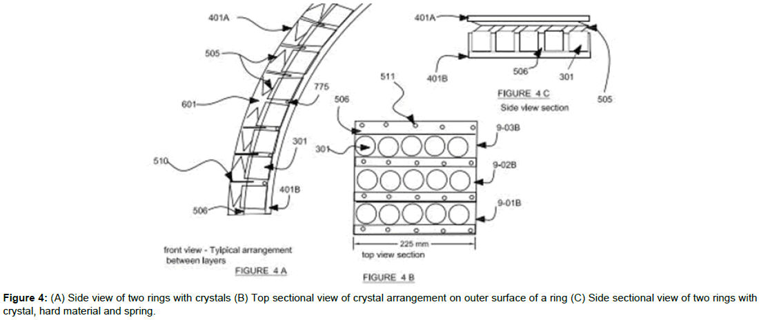
Figure 2B, shows the arrangement of crystals between the rings, on the outer surface of each inner ring, 9-01B to 9-172B are rows of crystal, shown mounted on upper surface of ring 401B, of which 9-01B, 9-18B are shown in figure, each row has 24 crystals along the width of the ring. 506 is hard material or ceramic, with height equal to maximum permissible compression size of mounted crystal, this hard material will prevent the crystals from over compression and seat the crystal rows. 775 is wire /wire duct for power transfer to collection electronics, 505 is a flat spring connecting the crystal top with the inner surface of the outer ring, in this case 401A. The tension of flat spring will be near that of maximum elongation force of crystal, ensuring spring expands to prevent over elongation of the crystal. 601 is the empty space between crystal top and outer ring, with the flat spring 505.
Each ring thickness is 0.5 mm, the crystal 1 mm and space above with spring under zero tension, is 0.5 mm, totaling 2 mm, when the ring-set remains in its original shape and form.
Figure 3
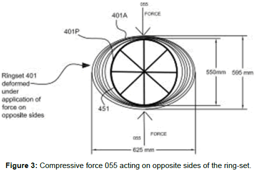
Figure 3 shows compressive force 055 acting on opposite sides of the ring-set, compressing the ring-set against the hard disc 451 within the innermost ring 401P. This result in the ring-set getting deformed, closing the space and subject that portion of the entire ring in the ringset to the full-applied force 055.
When the rings deform to form an elliptical shape, it expands outward on both sides in a plane perpendicular to the application of force 055, increasing the gaps between the rings, and therefore exerting a force of elongation on the piezoelectric crystals connected via the spring between the rings at these points of elongation.
Figure 4
Figure 4A shows side view of two rings with crystals in between; the 2 rings shown are 401A and 401B. 510 is a guide from bottom of top ring 401A to insert 511 in the hard ceramic 506, allowing free movement for compression and elongation but preventing any slippage between rings due to tangential force, the guide being just one of the methods to prevent any slipping, more as an illustration. Figure 4B is the top sectional view of crystal arrangement on outer surface of a ring, and Figure 4C is a side sectional view of two rings with crystal, hard material and spring.
Figure 5
Figure 5 shows the front and side view of the complete actuator assembly, it consists of two ring-set, compressed against each other by a predetermined adjustable force, in case of the model 500 Nm, adjustable from the mounting plate 801. Opposite to point of contact of the two ring-set, are rollers 701, running on roller bearing mounted on shaft 702, applying the same compression force, that is also adjustable from the mounting plate 801, resulting in both ring-set deforming to give each ring-sets an elliptical shape, with points of force application closing the gaps and exerting the applied force to all rings at the point shown as 001 in figure. The elliptical shape results in space between rings expanding at point’s perpendicular to plane of applied force, resulting in elongation force being exerted on crystals at the points identified as 002.
101A and 101B are drive motors, which run with the same speed but in opposite direction. The speed is adjustable and controlled by controller 1002A and 1002B, A single or dual drive can be used, for purpose of rotating the ring-set. A duel drive model is shown. As the ring-set makes one full rotation, each crystal in the ring-set experience two compressions and two elongations, a total of four actuations.
Figure 6
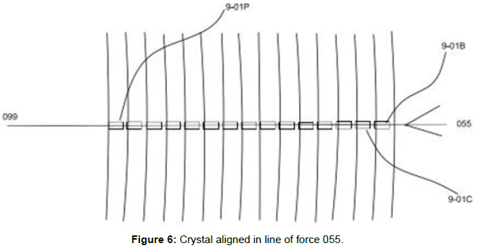
Shows crystal aligned in line of force 055, from point of force application to center of ring-set 099, ensuring uniform compression & elongation impact on crystal rows in each ring.
Figure 7
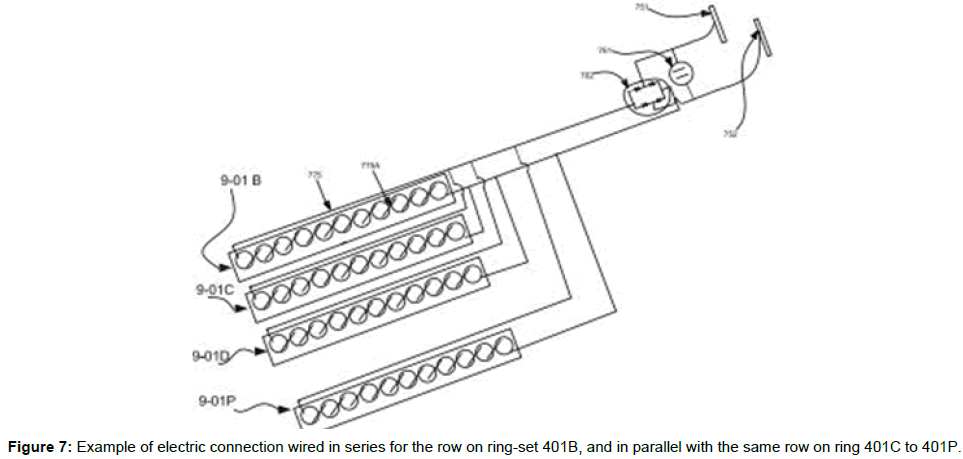
Shows the example of electric connection wired in series for the row on ring-set 401B, and in parallel with the same row on ring 401C to 401P. 775A is a bridge electrical connection, and 775 connecting electrical wire. Depending upon voltage requirement any combination of series/parallel connection can be used. The wires are then taken to a bridge rectifier 762, output of which is connected to conductors on a slip ring 751 and 752, with a capacitor of required capacity 761 connected in parallel with the bridge circuit. Silver graphite brushes can collect the power from the rotating slip ring. Contactless form of power pick up also can be considered.
Table 1
Table 1 shows the sizing of the ring-set, size of crystals considered, calculation of number of crystals that can be mounted on the ring and number of actuation per rotation of the actuator assembly.
| Piezo Electric Ringset Diamentional Details | ||||||||
|---|---|---|---|---|---|---|---|---|
| Ring size details | inner diamenter | 550 | mm | solid Ring Thickness | 0.5 mm | |||
| width | 225 | mm | crystal height | 1 mm | ||||
| outer diamenter | 610 | mm | 1 mm | |||||
| Piezo Crystal details | Diameter | Thickness | Power per acuation | |||||
| 8 mm | 1 mm | 60 microjoules. | ||||||
| Calculation of No. of crystals per ring set | ||||||||
| sl.no | dia | pie | circumference | space-each row | no. of rows | rounded | crystals each row | crystals each ring |
| 1 | 550 | 3.14 | 1727 | 10 | 172.7 | 172 | 24 | 4128 |
| 2 | 554 | 3.14 | 1739.56 | 10 | 173.956 | 173 | 24 | 4152 |
| While the outer rings can accommodate more rows and more crystals, to maintain a even impact of compression and elongation, and better power pick up, the same rows as calculated impact of compression and elongation, and better power pick up, the same rows as calculated | 172 | |||||||
| Therefore number of crystal in a ring-set will be 172 (rows) x 24 (crystals per row) x 15 (number of rings with crystal mounted) | 61920 | |||||||
| Total number of Crystals in actuator assembly equal to no. of ring-set in assembly (2) x crystals per ring-set (61920). | 123840 | |||||||
| Number of actuation per single rotation of assembly (no. of crystals x 4), when a crystal goes through one full rotation it experiences 2 compression and 2 elongation, total 4 actuations per rotation, so total actuation of an assembly per rotation | 495,360 | |||||||
Table 1: Piezo Electric Ringset Diamentional details.
The power in joules per actuation is assumed based on the following,
The common piezoelectric cigarette lighter uses piezo crystal to generate a spark that then ignites the butane gas, and produce continues flame, till gas is shutoff.
Butane gas has a typical Minimum Ignition Energy requirement of 250 micro joules, means it requires 250 micro joules or more energy to ignite butane. Piezo crystal actuation in a cigarette lighter is therefore capable of producing at least 250 micro joules of energy.
Taking this to be a direct output value, only half that value of 125 micro joules is considered for a single actuation. Again since there may be a variation with power generation during compression and elongation, and taking into account the losses of rectification etc., and to provide a further contingency for design error, it was decided to consider only 60 micro joules per actuation for purpose of calculation, i.e. 24% of the typical energy provided by a piezo actuator in a cigarette lighter.
Assumption of Energy per actuation– 60. Micro joules.
Based on the calculation in Table 1, about 4128 crystals can be mounted on the outer surface of inner most ring, while the outer rings can accommodate more, for purpose of uniform impact as per Figure 6, and better power collection, the same number is only accommodated in the model outer rings, resulting in a total of 61,920 piezo electric crystals in a ring-set and 123,840 of these in an actuator assembly.
For every rotation of the ring-set, each crystal goes through 2 compressions and two elongations, totaling 4 actuations per actuator rotation, resulting in 495,360 piezo crystal actuations per single rotation of the actuator.
For any doubt as to why the ring size was decided, original idea was to use the air space in car tire for energy harvesting from moving vehicle, and the rings were sized considering tire size 225/60 R16, but can be any size, based on power output requirement and practical limitation.
Figure 8
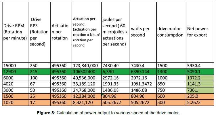
Shows the calculation of power output to various speed of the drive motor, As per the calculation when actuator rotation is about 1020 rpm, the power generator begins to exceed its drive power requirement, and as it approaches 12900 RPM, about 5000 watts of excess power is shown to be generated.
Figure 9
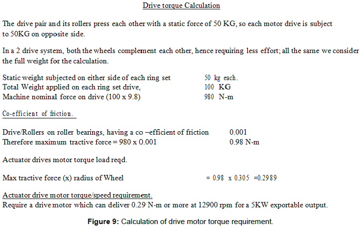
Shows calculation of drive motor torque requirement, based on calculation it is observed the drive motor is required to delivering a torque of 0.2989 N-m at speed of 12900 rpm, for a 5KW exportable power.
Figure 10
Shows graph and data of commercially available motor, that can deliver 0.29 N-m torque at 16,600 rpm, consuming 650 watts of power per motor. The figure with some margin is used for drive power calculations, in Figure 8.
Case Study
We have used a crystal size of 8 mm diameter and 1 mm height, cigarette lighter piezo crystal is much less, probably has a maximum diameter of 3 mm, in case a similar embedded crystal are used, assuming its height is 2 mm without protective case, and keeping the outer ring size constant, we have 6 mm difference between rings, so the innermost ring diameter will be 520 mm, with a 1632 mm circumference, it is possible to mount about 400 rows with each row having 72 crystals, which is about 432,000 crystals per ring-set, or 864,000 crystals per actuator. This will be 3,456,000 actuations per rotation, 207 watts per rotation. At 3000 rpm, i.e., 50 rotations per second, the Electric Energy generated will be about 10,350, and consumption by actuator will be much less than 1300 watts. This can be self-generating even if only compression cycle is considered [11].
References
- Harris RJ (1983) The investigation and control of gas explosions in buildings and heating plant. E&FN Spon in association with the British Gas Corp.
- AN1479 Application Note. High performance motor system for washing machines.
- Songsukthawan P, Jettanasen C (2015) Performance Analysis of Maximum Power Transfer in Piezoelectric Energy Harvesting. In Proceedings of the International Multi Conference of Engineers and Computer Scientists.
- Nelson WG (2010) Piezoelectric Materials: Structure, Properties and Applications.
- Marshiana D, Sherine ME, Sunitha N, Vinothkumar C (2016) Footstep Power production using Piezoelectric Sensors. Res J Pharmacy and Techn 9: 831-834.
- Calio R, Rongala UB, Camboni D, Milazzo M, Stefanini C, et al. (2014) Piezoelectric energy harvesting solutions. Sensors 14: 4755-4790.
- Kuchta JM (1985) Investigation of fire and explosion accidents in the chemical, mining, and fuel-related industries.
Citation: Thomas A (2018) Self Sustained Renewable Energy Generator. Innov Ener Res 7: 184. DOI: 10.4172/2576-1463.1000184
Copyright: © 2018 Thomas A. This is an open-access article distributed under the terms of the Creative Commons Attribution License, which permits unrestricted use, distribution, and reproduction in any medium, provided the original author and source are credited.
Share This Article
Recommended Journals
Open Access Journals
Article Tools
Article Usage
- Total views: 4204
- [From(publication date): 0-2018 - Feb 22, 2025]
- Breakdown by view type
- HTML page views: 3530
- PDF downloads: 674

