Seismic Behavior of Historic Masonry Monasteries in Sikkim in the 2011 M 6.9 Sikkim Earthquake: Case Study of Hee Gyathang Monastery, North Sikkim, India
Received: 21-May-2017 / Accepted Date: 24-Jun-2017 / Published Date: 30-Jun-2017 DOI: 10.4172/2168-9717.1000205
Abstract
The Himalayan region is, one of the most seismically vulnerable and tectonically active zones in the world. Sikkim is a state in North-East India, situated on the Himalayan arc. Sikkim is dotted with numerous Buddhist monasteries dating back to the 17th century. These historical monastery structures are a part of the rich cultural heritage of the state, being structures of social, cultural and religious significance to the community. The old monasteries are typically load bearing structures where stone masonry and timber are used extensively as columns, beams, floors, roofs and also in staircases. The monasteries follow some spatial characteristics such as regular geometrical shapes in plan with an assembly hall and front verandah, and are usually one or two storeys high with diminishing upper storeys topped by light weight sloped roofs. The M6.9 earthquake on September 18, 2011, in Sikkim has clearly demonstrated the vulnerability of the historical monastery structures. The evaluation of the earthquake vulnerability of monasteries is a necessary first step for their protection in future earthquakes. This paper analyzes the performance of one of the non-engineered monastery structure made with load bearing stone masonry - the century old hilltop Hee Gyathang Monastery located in the North District about 30 kms from Mangan. Structural analysis by demand capacity method of this monastery proves that the monastery is unsafe after the 2011 M 6.9 Sikkim Earthquake.
Keywords: Sikkim earthquake; Monastery; Structural analysis; Demand capacity method
77352Introduction
Sikkim is a state in North-East India, situated on the Himalayan arc that is made up of a number of parallel fault systems, namely, Himalayan Frontal Fault (HFF), Main Boundary Thrust (MBT), Main Central Thrust (MCT), Trans Himalayan Fault and the Indus- Tsangpo Suture [1]. In the Sikkim Himalayas, the MBT and MCT are not parallel which has been reported as a major controlling factor for earthquakes that has made the entire state highly earthquake prone [2]. Sikkim has about 250 Buddhist monasteries, the oldest dating back to the seventeenth century. The monasteries are made with load bearing stone masonry along with timber frame. An earthquake of magnitude 6.9 occurred on 18th September at 18:11 hrs IST in Sikkim- Nepal Border region. The preliminary hypo-central parameters of this earthquake, as estimated by the Seismic Monitoring Network of India Meteorological Department (IMD) are given in Table 1. This region the monasteries are situated in hilly terrain not far from the China-Tibet border. The monasteries located in this area experienced extensive damages during this earthquake. Hee Gyathang Monastery was built in 1914 and is representative of the architectural and structural typology mentioned earlier. The monastery caters to the devotional needs of the Nyingmapa Sect of Buddhism. This remotely located monastery is rich in architectural value and is of special significance to devotees, adding to its socio cultural value for the community.
| Date of occurrence | 18/09/2011 |
| Time | 18 11 hrs (IST) |
| Magnitude | 6.8 |
| Focal depth | 10 Km |
| Epicentre | Latitude and Longitude 27.70° N and 88.20° E |
| Region | Sikkim-Nepal Border region. |
Source: http://www.imd.gov.in/section/nhac/dynamic/eq.pdf. (last accessed 19.9.16)
Table 1: Data on 2011 Sikkim Earthquake.
Location/Accessibility of Hee Gyathang
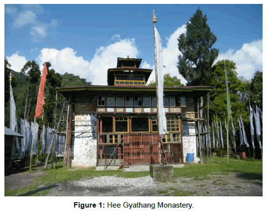
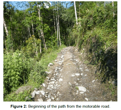
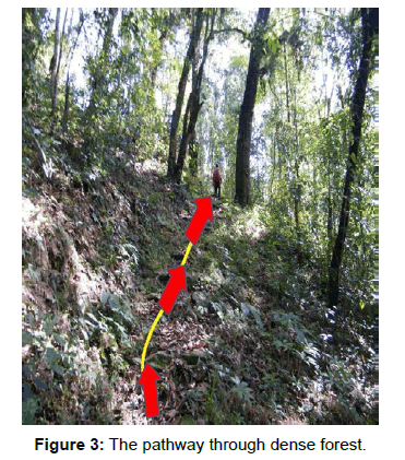
Monastery The Hee Gyathang Monastery (Figure 1) is situated in a solitary hill top location. The nearest settlement is Hee Gyathang village on the road from MangantoGor via Sankalan. The monastery is located 2.5 kms from the village and can be accessed only on foot through an arduous one hour hike through a steep pathway through dense forests, without any human habitation along the way (Figure 2). The monasteryis built on a small patch of flat ground about 1600 sqm area on a hill top at an altitude of 1669 meter (Figure 3). The geographical coordinates are simultaneously 27.4750 N and 088.5010 E.
Planning and Site Consideration
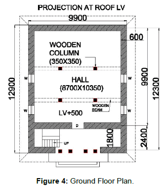
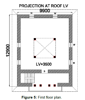
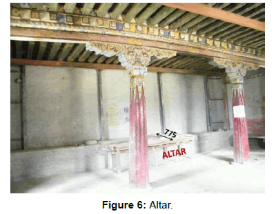
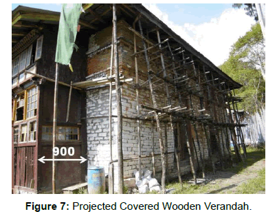
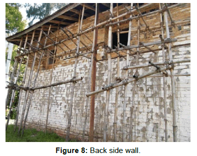
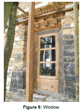
The old two storied load bearing monastery structure sits on a 500 mm high plinth amidst soft landscape.The ground floor has an assembly hall (8.7 m × 10.35 m) with an altar of 775 mm width at its rear end. The ground and first floors have the same plan footprint (Figures 4-6). Presently, the statues have been shifted to the new monastery while the old one lies abandoned. Both the floors have similar fenestration with two windows located on the northern and southern walls. The front of the monastery has a wooden verandah of 900 mm width (Figure 7). The fenestration pattern on the rear side is not the same on both the floors. While the first floor has two window openings, the ground floor has none (Figure 8). It is noticed that the old windows have been replaced by new ones (Figure 9).
Planning and Site Considerations
The old two storied load bearing monastery structure sits on a 500 mm high plinth amidst soft landscape. The ground floor has an assembly hall (8.7 m × 10.35 m) with an altar of 775 mm width at its rear end. The ground and first floors have the same plan footprint (Figures 4-6). Presently, the statues have been shifted to the new monastery while the old one lies abandoned. Both the floors have similar fenestration with two windows located on thenorthern and southern walls. The front of the monastery has a wooden verandah of 900 mm width (Figure 7). The fenestration pattern on the rear side is not the same on both the floors. While the first floor has two window openings, the ground floor has none (Figure 8). It is noticed that the old windows have been replaced by new ones (Figure 9).
Structural System
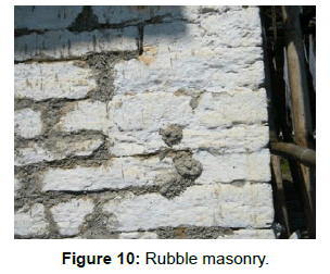
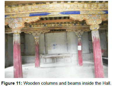
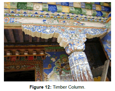
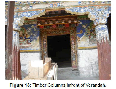
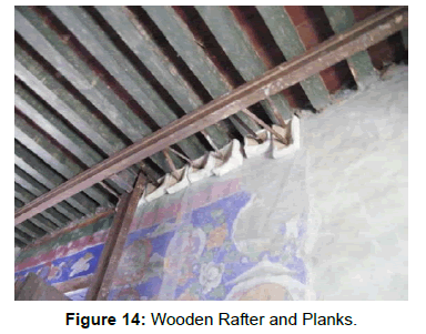
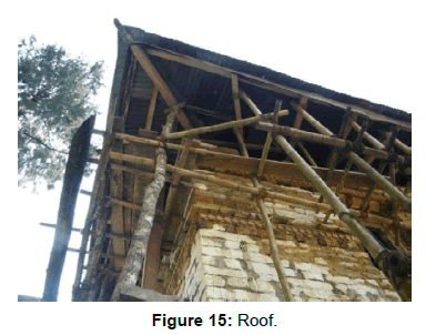
The old monastery is made with Random Rubble stone masonry structure (Figure 10) with a thickness of 600 mm. Four timber posts are located at the centre of the assembly hall, only two horizontal beams are observed above the wooden posts spanning only in the “X” direction (Figure 11).The wooden posts are decorated at the top (Figure 12). Two decorated wooden posts are located at the entrance of the front verandah (Figure 13). No bands are present in the monastery. Floors are made with timber planks. Wooden rafters hold the timber plank in the first floor (Figure 14). Roof is covered with G.I sheets (Figure 15).
Seismic Load Analysis
The Demand Capacity Ratio (DCR) method is an useful tool to determine the capacity of a building to resist seismic action, through determination of the seismic demand and the calculation of the ratio of demand vis a vis capacity [3]. DCR values less than or equal to one indicate that a structure is safe. DCR values in excess of one indicate that a structure is unsafe since the structural capacities are less than the seismic demand imposed on the building. The combined stress due to direct axial compression and stress is given by expression P/A ± M/Z where,
P=Axial compressive force on the determined wall
A=area of the wall under consideration.
M=Moment at the base of wall.
Z=Section modulus=I/y=bd3/12 ÷ d/2=bd2/6 [where, b=Breath, d=Depth].
I=Moment of Inertia.
A negative value for the above expression indicates that the structure will be unsafe, that is, the masonry wall is subjected to tensile stress, which it is inherently incapable of resisting.
DCR Computations were done for shear stress, tensile stress and overturning.
For shear stress, DCR=Vavg,I/fs
For Tensile stress, DCR=σ t/c,i/fb
For Overturning, FOS=Ms/MO
Where,
Bending stress=σbi
Direct Axial Stress=σdi
Average Shear stress=Vavg, I=Qi/Awall
fs=The permissible shear stress calculated on the area of bed joint shall be in accordance with clause 5.4.3 of IS:1905-1987
Ms=Stabilizing moment due to dead load at bottom of the wall
M0=Total moment of the bottom wall
Overturning Moment=FOS=Ms/Mo
The design parameters were taken from IS 1893:2002.
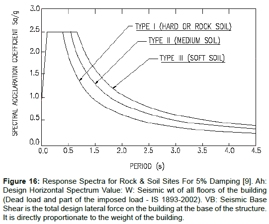
The entire state of Sikkim lies in Zone IV with maximum expected intensities of VIII on the Modified Mercalli Intensity (MMI) scale. As per IS 1893:2002 (Part 1) the Zone Factor Z is 0.24 for seismic zone IV. The value of Importance Factor, I is chosen 1.2 for being religious building. For unreinforced load bearing masonry wall building has the Response Reduction Factor, R is 3 [4-6]. During earthquake shaking a building will oscillate to and fro in any mutually perpendicular directions. The Fundamental Natural Period (time taken to complete one back and forth motion in seconds), derived from the expression Ta=0.09h/√d (IS 1893:2002), where, h=Height of building, in metres, d=Base dimension of the building at the plinth level, in m, along the considered direction of the lateral force. (To get the lesser value of ‘T’ the longer dimension of the base is considered.) Sa/g=Spectral Acceleration Co-efficient (As per the graph for Rocky and hard soil considering 5% damping the value of Sa/g is 2.5.) (Figure 16 and Tables 2-6) [7-9].
Figure 16: Response Spectra for Rock & Soil Sites For 5% Damping [9]. Ah: Design Horizontal Spectrum Value: W: Seismic wt of all floors of the building (Dead load and part of the imposed load - IS 1893-2002). VB: Seismic Base Shear is the total design lateral force on the building at the base of the structure. It is directly proportionate to the weight of the building.
| SEISMIC WEIGHTS=W ( KN) | |||
|---|---|---|---|
| W1(Ground Floor) | 2205KN | Zone Factor=(Z)=0.24 | Design horizontal spectrum value=Ah=0.12 |
| W2( First Floor) | 1890KN | Importance Factors=(I)=1.2 | Seismic weights (W)= |
| 4740KN | |||
| Dead load (DL) | 478.9KN | Response Reduction Factor=(R)=3 | VB=Ah X∑W=711KN |
| Live Load (LL)= | 63.9KN | Spectral Acceleration Co – efficient=(Sa/g)=2.5 | |
| Dead load of flexible roof= | 100KN | Ah=Z/2 x I/R x Sa/g=0.12 | |
| Total weight of the structure (W) | 4740KN | ||
NOTE: This design horizontal seismic coefficient Ah is determined by the following expression provided that for any structure with T ≤ 0.1 Sec the value of Ah will not be taken less than Z/2 whatever the value of I/R.
Sa/g=Spectral Acceleration Co – efficient depends on i) Fundamental Natural Period ‘T’ and ii) the type of soil at the site. Soil type of Sikkim is Hard Rock.
The Sa/g value can be derived from the graph (Figure 16) - Response Spectra for Rocky Soil Sites For 5% Damping.
Table 2: Design shear calculation. Wi: seismic weight of floor, hi: height of floor I measured from base, n: number of storeys in the building, Vavg,I: The average shear stress of a building at any level, Qi: storey shear or designed lateral force at floor (i) at the level under consideration determined, Aw: summation of the horizontal cross sectional area of all shear walls in the direction of loading. The wall area shall be reduced by the area of any openings.
| Story Level | Wi (KN) | hi(m) | Wihi2 (KN m2) | Wihi2ΣWihi2 | Q = VBX Wihi2ΣWihi2 | |
|---|---|---|---|---|---|---|
| X Direction (KN) | Y Direction (KN) | |||||
| Ground | Wi1=2747.7 | 3.5 | 33660.1 | 0.286 | Q1=203.3 | 203.3 |
| First | Wi2=1990 | 6.5 | 84077.5 | 0. 714 | Q2=507.7 | 507.7 |
| 11773.76 | 1 | 711 | 711 | |||
Table 3: Lateral load distribution with height by the static method.
| For Flexible Diaphragm | |||
|---|---|---|---|
| Q1 | =203.3 KN | Q2 | =507.7 KN |
| Vmax | =67.8 KN/m | Vmin= | =41.3 KN/m |
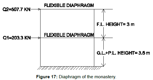
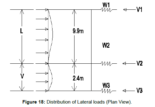
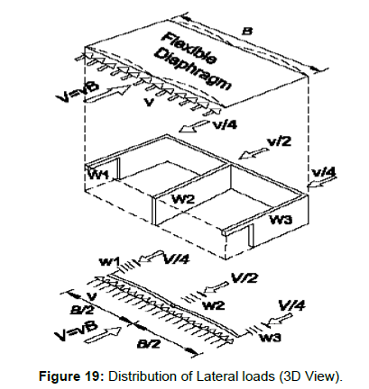
| Moment causes due to V2 (Figure 20) | =355.81KNm | Moment causes due to Vmax at bottom of the wall (Figure 19) | =1651.0 KNm |
| Total moment of bottom wall=( M0)=(1651.0 +355.81) KNm=2006.81KNm ( Figure 19) | |||
Table 4: Lateral Load Distribution for flexible diaphragm.
| Moment of Inertia=I | bd3/12 | 40.218 m4 |
| Bending stress=σb.i | M0/I * Y | 232.03KN/m |
| Direct Axial Stress=σd,i | σd,i=P/A | 130KN/m2 |
| Direct and Bending stress=σt/c,i | σt/c,i=σd,i±σb,I | + 362.03KN/m2 and -102.03KN/m2 |
| Average Shear stress at the Bottom of the Wall=Vavg,I | Qi/Awall | 63.74KN/m2 |
| Over turning Moment | FOS=Ms/M0 | 1.68 |
Table 5: The combined stress due to direct axial compression.
| Permissible stresses | Actual stresses | DCR | Remarks | |
|---|---|---|---|---|
| Shear Stress | fs=0.22 | Vavg,I=0.06374 | Vavg/fs=0.29 | This DCR value is within the allowable limit which indicates the structure safe under shear stress. |
| Compressive Stress | fb=0.87 | σt/c,I=0.36203 | σt/c,i/fb=0.416 | The structure is safe in Compressive stress as the DCR value is less than unity |
| Tensile stress | ft=0.05 | σt/c,I=0.10203 | σt/t,i/ft=2.04 | This value (2.04) is greater than unity indicates that the masonry structure is under tension beyond its allowable value. |
| Over turning | 1.5/FOS=0.89 | The structure is safe in Overturning as the DCR value is less than unity |
Table 6: Computation of DCR.
Findings and Concluding Remarks
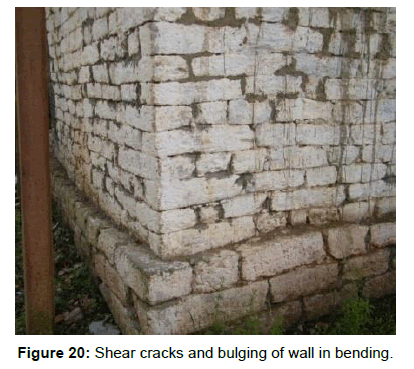
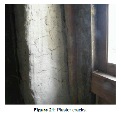
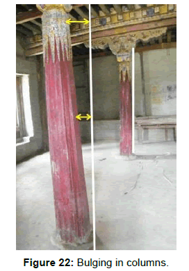
After the 2011 earthquake, it was observed that the old structure had suffered edirreparable damages. Visual inspection revealed the deteriorated condition of the monastery due to these damages (Figures 17-19). The random rubble masonry walls suffered bulging due to out of plane bending (Figure 20), diagonal and plaster cracks developed on the inside walls plaster (Figure 21) The timber posts also suffered bending (Figure 22). The damages sustained may be attributed to the inability of the walls to withstand the tensile stresses generated during earthquake induced shaking. Clearly, these cracks have weakened the structure and remedial measures need to be taken to prevent their further propagation. However, it is noteworthy that the structure has not collapsed despite suffering such widespread damage. The DCR values indicate that the structure should have sustained Grade 1 damage as per IS 1893: 2002, that is, fine cracks in plaster. However, the structure experienced moderate and heavy damage including small, large and deep cracks in plaster, bulging of columns, gaps in walls and loss of cohesion in parts of the building indicating that the actual damage level sustained was Grade 3 as per Is Code 1893: 2002. So this analysis has pointed out that the historical monasteries have become vulnerable and are in jeopardy. So far very little work has been done to formally assess the vulnerability of the historical structures in the earthquake prone state Sikkim. It is not too late to evaluate the earthquake vulnerability to all old historic monasteries and suggest a way forward for their protection and preservation.
References
- Honegger K, Dietrich V, Frank W, Gansser A, Thoni M, et al. (1982) Magmatism and metamorphism in the Ladakh Himalayas (the Indus-Tsangpo suture zone). Earth and Planetary Science Letters 60: 253-292.
- De R, Kayal JR (2003) Seismotectonic model of the Sikkim Himalaya constraint from microearthquake surveys. Bulletin of the Seismological Society of America 93: 1395-1400.
- Agrawal SK, Chourasia A (2002) Methodology for Seismic Vulnerability Assessment of Building Stock in Mega Cities A Workshop on Microzonation. Interline Publishing, Bangalore.
- IS1893 Part 1 (2002) Indian Standard Criteria for Earthquake Resistant Design of Structures. Bureau of Indian Standards, New Delhi.
- IS 1905-1987 (1987) Code of Practice for Structural Use of Unreinforced Masonry. Bureau of Indian Standards, New Delhi.
- Murty CVR (2010) Earthquake Tips. Learning Earthquake Design and Construction, National Information Centre of Earthquake Engineering, IITK BMTPC.
- Seismic Design Guide for Low-Rise Confined Masonry Buildings- EERI (2011).
- http://www.sikkimeccl.gov.in/History/Monasteries/North/HeeGyathang.aspx
Citation: Joti S, Mitra K, Mitra S (2017) Seismic Behavior of Historic Masonry Monasteries in Sikkim in the 2011 M 6.9 Sikkim Earthquake: Case Study of Hee Gyathang Monastery, North Sikkim, India. J Archit Eng Tech 6: 205. DOI: 10.4172/2168-9717.1000205
Copyright: © 2017 Joti S, et al. This is an open-access article distributed under the terms of the Creative Commons Attribution License, which permits unrestricted use, distribution, and reproduction in any medium, provided the original author and source are credited.
Share This Article
Recommended Journals
Open Access Journals
Article Tools
Article Usage
- Total views: 4724
- [From(publication date): 0-2017 - Mar 31, 2025]
- Breakdown by view type
- HTML page views: 3870
- PDF downloads: 854

