Research Article Open Access
Product Design and Analysis of Automotive Carrier
Lakshmi prasanna reddy polamreddy*, S.C.SireeshaDepartment of Mechanical Engineering, QIS College of Engineering & Technology, Andhra Pradesh, INDIA
- *Corresponding Author:
- Lakshmi prasanna reddy polamreddy
Department of Mechanical Engineering
QIS College of Engineering & Technology
Andhra Pradesh, INDIA
Visit for more related articles at International Journal of Advance Innovations, Thoughts & Ideas
Abstract
There are different types of carriers present in the General Motors automotive plant which are intended to perform specific application (like one with assembly is used for handling various components for assembly, paint skid carrier is used for painting the BIW etc.). There are around 450 carriers on a whole in the entire plant and per hour it has to produce around 80 vehicles and total of 640 vehicles were produced in a shift. Break down of any one carrier will result into bottle neck formation in the assembly plant which will result into increased cost of production and subsequently causes loss to the organization. The cost of designing and manufacturing of single carrier is also high.
The main objective of this work is to develop a new carrier which can perform operations of two to three carriers together (for example, carrier which hold good for both fitting and painting BIW). This has been achieved by carefully studying the product development process and the system in the entire assembly plant. The carrier design in general is a complex methodology and to arrive at a solution which yields a good performance is a tedious task. Since the carriers have a complex geometry and loading patterns, there is no well-defined analytical procedure to analyse the carriers. So the numerical method of analysis is adopted, in which ‘Finite Element Technique’ is most widely used method. Based on FE simulation, modifications and optimization has been done on the entire carrier assembly which not only with stands the stress developed during the entire loading cycles but also passes with design safety factors. Prototype has been built based on FE results and it has been validated.
Keywords
Product Design, Analysis, Finite Element Technique, Automotive Carrier.
Introduction
Product Design and Development
It is for the determination and specification of the parts of a product and their interrelationship so that they become a unified whole. The design must satisfy a broad array of requirements in a condition of balanced effectiveness. A product is designed to perform a particular function or set of functions effectively and reliably, to be economically manufacturable, to be profitably salable, to suit the purposes and the attitudes of the consumer, and to be durable, safe, and economical to operate. For instance, the design must take into consideration the particular manufacturing facilities, available materials, know-how, and economic resources of the manufacturer. The product may need to be packaged; usually it will also need to be shipped so that it should be light in weight and sturdy of construction. The product should appear significant, effective, compatible with the culture, and appear to be worth more than the price. On a whole Product design and development can be defined as: Idea generation, Concept Development and Testing and manufacturing or implementation of a physical object or service.
Phases of Product Development Process
There are six phases in a generic product development process. They are
1. Planning
2. Concept Development
3. System level Design
4. Detail design
5. Testing and refinement
6. Production ramp-up
Planning
Planning activity is often referred to as “phase Zero” since it precedes the project approval and launch of the actual product development process. This phase begins with corporate strategy and includes assessment of technology developments and market objectives. The output of planning phase is the project mission statement, which specifies the target market of the product, business goals, key assumptions and constraints.
Concept Development
Concept development process includes following activities
• Identifying customer needs
• Establishing target specifications
• Concept generation
• Concept selection
• Concept testing
• Setting final specifications
• Project planning
System Level Design
This phase includes the definition of the product architecture and decomposition of the product into sub-assemblies and sub components. The final assembly scheme for the productions system is usually defined during phase as well. The output of this phase usually includes a geometric layout f the product, a functional specification of each of the product’s subsystems and a preliminary process flow diagram for the final assembly process.
Detail Design
The detail design phase includes the complete specifications of the geometry, materials and tolerances of all of the unique parts in the product and the identification of all of the standard parts to be purchased from suppliers. A process plan is established and tooling is designed for each part to be fabricated within the production system. The output of this phase is the controlled documentation of the product-the drawings or computer files describing geometry of each part and its production tooling, the specifications of the purchased parts, and the process plans for the fabrication and assembly of the product. Two critical issues addressed in the detail design phase are production cost and robust performance.
Testing and Refinement
The testing and refinement phase involves the construction and evaluation of multiple preproduction versions of the product. Early prototypes are usually built with production intent parts with same geometry and material properties as intended for the production version of the production but not necessarily fabricated with actual processes to be used in production. Alpha prototypes are tested to determine whether the product will work as designed usually built with parts supplied by the intended production processes but may not be evaluated internally and are also typically tested by customers in their own use environment. The goal for the beta prototypes is usually to answer the questions about performance and reliability In order to identify necessary engineering changes of the final product.
Production Ramp Up
In the production ramp up phase, the product is made using the intended production system. The purpose of the ramp-up is to train the work force to work out any remaining problems in the production processes. Products produced during production ramp-up are sometimes supplied to preferred customers and are carefully evaluated to identify any remaining flaws. The transition from production ramp-up to ongoing production is usually gradual. At some point in this transition, the product is launched and becomes available for wide spread distribution.
Objective
The goal of this study is to ascertain the ability of the structure (carrier) to withstand the stresses developed under the following loads and predict the material performance regarding deformation, design life and factors of safety: Case 1 : Monoplane; Case 2 : 5 deg Decline; Case 3 : 5 deg Incline; Case 4: Start Stop Condition

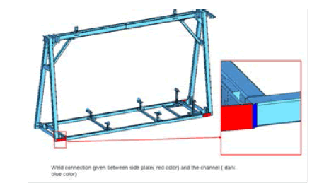
Figure 1: Carrier Assembly.

Figure 2: FE Modeling of Carrier Assembly.
FE Modelling
Components of OHPF carrier have been modelled with Shell and Solid elements. All weld connections are assumed to be full effective and have been simulated with rigid connections. Bolt connections have been simulated with 1d elements. Global size of 15 mm (0.591 inch) has been maintained capturing all the critical geometry.
Material Properties
Material properties of different components of carrier assembly were assigned properly as per the requirement:
For King pins ASTM 1045 cold drawn steel have been used
• Young’s Modulus : 29*106 psi
• Poisson’s ratio : 0.26
• Yield strength : 77 ksi
• Allowable Yield Strength for FOS of 4 and Load factor of 2.5:48.12 ksi
• Ultimate strength : 91 ksi
• Allowable UTS for FOS of 6.5 and Load factor of 2.5: 22.35 ksi
For all Bolt and nut assembly ASTM A325 have been used
• Young’s Modulus : 29*106 psi
• Poisson’s ratio : 0.29
• Yield strength : 92 ksi
• Allowable Yield Strength for FOS of 4 and Load factor of 2.5:57.5 ksi
• Ultimate strength : 120 ksi
• Allowable UTS for FOS of 6.5 and Load factor of 2.5:75 ksi
For all steel except tubing ASTM A36 have been used
• Young’s Modulus : 29*106 psi
• Poisson’s ratio : 0.26
• Yield strength : 36 ksi
• Allowable Yield Strength for FOS of 4 and Load factor of 2.5:22.5 ksi
• Ultimate strength : 58 ksi
• Allowable UTS for FOS of 6.5 and Load factor of 2.5: 24.2 ksi
For structural tubing ASTM A500 Gr B have been used
• Young’s Modulus : 29*106 psi
• Poisson’s ratio : 0.29
• Yield strength : 36 ksi
• Allowable Yield Strength for FOS of 4 and Load factor of 2.5: 22.5 ksi
• Ultimate strength : 58 ksi
• Allowable UTS for FOS of 6.5 and Load factor of 2.5:24.2 ksi
Boundary and Loading Condition
The loading and boundary conditions of the Carrier assembly are as shown below;

Figure 3: Boundary Conditions.

Figure 4: Monoplane and Decline Conditions.

Figure 5: Incline and Start stop Conditions.
Simulation
Entire development process has been divided into three phases. They are 1. α-phase (Mule Stage) 2. β-phase (Compact phase) 3. γ-phase (Definitive phase).
α-Phase (Mule Stage)
This is the first phase of development process, in this phase entire team of designers and engineers sit together and they got to one design. This design has been analysed for four load cases of monoplane, incline, decline and start stop. The results of the carrier assembly for all load cases are as shown below.

Figure 6: Monoplane stress plot with and without kingpin.

Figure 7: 5deg decline stress plot with and without kingpin.

Figure 8: 5deg incline stress plot with and without kingpin.

Figure 9: 5deg start-stop stress plot with and without kingpin.

Table 1: FE Results for First phase.
β -Phase (Compact phase)
As the model is failing in first phase of design, some gussets has been added to improve its strength, modified design is as shown below:

Figure 10: 5deg Modified Design.
Again FE simulation has been carried out for all the four cases and its results are tabulated as shown below.

Figure 11: 5deg Decline stress plot with and without kingpin for 2nd phase.

Figure 12: 5deg incline stress plot with and without kingpin for 2nd phase.

Table 2: FE Results for 2nd phase.
As it is evident from the above table that maximum stress among all load cases is 40.76 ksi which is less than yield strength of material. Carrier has minimum FOS of 3.8 in yield and 6.2 in ultimate which is less than the required criteria. As the design is again failing in two load cases again design suggestions has been made in the last phase of design.
γ -Phase (Compact phase):
Following design suggestions were made in this compact phase:
Following are the overall stress for the above phase

Table 3: FE Results for 3rd phase.
The maximum stress among all load case is 26.98 ksi which is greater than yield strength of the material and the structure has minimum FOS of 4 in yield and 6.4 in ultimate which yields the required criteria. After this phase, bolt connections in the model are also analysed to check whether they were able to with stand the load coming on to it or not. For this purpose load case which is having more stress is taken out with weld connections and it is again analysed for three cases:
Case 1: Bolt nut assembly has been simulated and the induced stress in the bolt & nut assembly has been studied.
Case 2: Study the reaction forces coming on to the bolt and calculate the axial and shear stress on the bolt
Case 3: Study of the I-beam plate due to the pre-load in the bolt.
Case 1:
Bolts and nuts in the assembly are modelled with hexa-penta elements and the loads coming on to it are studied. It is evident from the following picture that maximum stress coming on to the bolts is 3.7 ksi which is much less than the yield strength of the material.

Figure 13: Stress on bolt and nut assembly.
Case 2: Reactions on the bolts.
In order to simulate this case all the bolts were modelled with conn3D2 elements in the abacus and the reactions were determined and listed below

Table 4: Bolt Reaction Loads.
Case 3: Reactions on the bolts
In order to simulate this case pretension load has to be calculated and it has to be applied over the surface of the region where bolt head will come in contact with the base. Preload calculations are carried out as follows
Mt=0.2 Pi *d Where Mt =Torque = 280 lbs –ft(given value); Pi= Preload ; d= diameter of the bolt.
Hence Pi ~ 2240 lbs

Figure 14: Stress on bolt and nut assembly due to pretension load.
Hence maximum load of 10 ksi is coming on all bolts which show that bolts are much safer.
Conclusion
In this new updated design the maximum stress among all load configurations is 22.57(without king pin) and 26.98 (with king pin condition) which is less than the yield strength of the material with factor of safety of 7.1 and 4 respectively. The carrier has a minimum factor of safety of 4.0 on yield strength and 6.4 on ultimate strength of the material. Based on the bolt analysis, the maximum stress on bolt is well less than the yield strength of the Bolt material. Based on maximum stresses, the life time of carrier is estimated to be 41.14 years. Hence after prototype testing has been done , strains were compared with original FE Analysis, hence the results with in tolerance limits hence the system meets overall design criteria specified during initial stages of product development. Hence a new carrier which holds good for performing operations such as fitting and painting simultaneously has been designed by achieving required design criteria.
References
- Product design: a practical guide to systematic methods of new product developmentBy Mike Baxter.
- Integrated product and process design and development: The product realization process By Edward B. Magrab.
- Product development and design for manufacturing: a collaborative approach to producibility and reliability By John W. Priest, José M. Sánchez.
- J New product development and production networks : Global industrial experience By Ulrich Jürgens.
- Product Design and Manufacturing By A. K. Chitale, R. C. Gupta; http://www.dmwcc.com/.
- Barabba V P, Zaltman G, (1991), Hearing the voice of the market: competitive advantage through creative use of market information, Harvard Business School Press, USA.
- Jordan P W, (2000), Designing pleasurable products: an introduction to the new human factors, Taylor & Francis, London.
- Cutherell D, (1996), Product Architecture, The PDMA Handbook of New Product Development.
Relevant Topics
- Advance Techniques in cancer treatments
- Advanced Techniques in Rehabilitation
- Artificial Intelligence
- Blockchain Technology
- Diabetes care
- Digital Transformation
- Innovations & Tends in Pharma
- Innovations in Diagnosis & Treatment
- Innovations in Immunology
- Innovations in Neuroscience
- Innovations in ophthalmology
- Life Science and Brain research
- Machine Learning
- New inventions & Patents
- Quantum Computing
Recommended Journals
Article Tools
Article Usage
- Total views: 15871
- [From(publication date):
November-2012 - Apr 05, 2025] - Breakdown by view type
- HTML page views : 11304
- PDF downloads : 4567