Preliminary Structural Analysis for the Archaeological Reconstruction of the Ancient Palace Grat Be'al Gibri in Yeha, Ethiopia
Received: 03-May-2023 / Manuscript No. jaet-23-96291 / Editor assigned: 05-May-2023 / PreQC No. jaet-23-96291 (PQ) / Reviewed: 19-May-2023 / QC No. jaet-23-96291 / Revised: 22-May-2023 / Manuscript No. jaet-23-96291 (R) / Published Date: 29-May-2023 DOI: 10.4172/2168-9717.1000337
Abstract
Unique objects of cultural heritage are usually thoroughly investigated from the archaeological viewpoint. However, lots of relevant questions regarding these objects remain still open without specific investigations from the engineering viewpoint, especially those of ancient construction knowledge and technology. The present work is a preliminary attempt to apply modern engineering tools to study a virtual structure of an ancient building in Ethiopia which has been reconstructed within the framework of an Ethiopian-German cooperation project before. The palatial building called Grat Be'al Gibri in Yeha is the largest preserved structure of its kind in South Arabia and North-East Africa. Its special feature is the construction of the walls consisting of timber-laced rubble masonry. There are indicators that it could be a multi-story building, although only parts of the ground floor and its wall constructions are preserved. The engineering investigations should help answering a few important questions regarding this building, among others about the ground plan form, thickness of the walls, the function of timber beams for the wall, their placement and orientation as well as a potential story number in the building. For this purpose, the building is tentatively investigated from the structural viewpoint taking into account enormous uncertainties with respect to structural and material parameters. Based on the 3D geometrical (CAD) model of the building available from the archaeological reconstruction, a numerical linear elastic macro model within the finite element method has been developed for all structural simulations within this study. The walls are assumed to consist of a homogeneous material whose properties are estimated from the relevant literature and are taken into account by their minimum, mean and maximum values within some physically reasonable ranges. The detailed modeling of a heterogeneous timber-reinforced masonry structure of the walls on the meso scale is omitted in this first step. The structural performance under dead load is evaluated with respect to the overall spatial deformation and principal stresses on critical locations. Based on the obtained results, it is finally proposed by the authors which next steps should be done for further investigations to answer archaeological questions which could not be answered yet.
Keywords
Ancient palace building; South Arabian architecture; Virtual archaeological reconstruction; Timber-laced masonry; Structural simulation; Finite element model; Stress and deformation state; Ethio-Sabaean culture
Introduction
Within the framework of the Ethiopian-German cooperation project, cultural contacts between Southern Arabia and northern Ethiopia in the early 1st millennium BC have been investigated archaeologically in northern Ethiopia since 2009 at the ancient settlement of Yeha [1]. The Ethiopian Heritage Authority (Addis Ababa, Ethiopia), the Tigrai Cultural and Tourism Bureau (Mekelle, Ethiopia) and the Orient Department of the Deutsches Archäologisches Institut (DAI) are involved. The cooperation project is carried out with the Research Centre Ancient South Arabia and Northeast Africa of the Friedrich-Schiller-Universität Jena with support of the DFG (Deutsche Forschungsgemeinschaft). The importance of Yeha can be seen not least in the preserved monumental architecture, which differs from the other Ethio-Sabaean sites not only in terms of its size, but also in terms of its quality and the effort required to erect it [2]. One of such unique buildings, which is the subject of the present investigation, can be dated to around 800 BC by 14C dating. It is the palatial administrative building called Grat Be'al Gibri. With its ground plan size of around 60 m × 50 m, this monumental structure, which far surpasses all comparable buildings in South Arabia and East Africa, is characterized by the special construction of its walls above a podium. They are made as a composite construction of quarry stone masonry and timber. The building was already destroyed in ancient times by a fire disaster and in the following centuries by stone robbery and reuse of building material. Therefore, only the walls of the ground floor have partially survived apart from the podium. However, it is recognizable from the timber beam imprints in the walls that these beams have been placed exclusively horizontally in the masonry of the walls. Thus, this construction deviates significantly from that of comparable buildings in South Arabia, where a system of alternating horizontal and vertical beams was widespread [3,4]. Although only the base and the walls of the ground floor have survived, there are indicators that the palace could have been a multi-story building. In spite of extensive archaeological investigations on the palace building, several relevant questions remain still open without specific investigations from the engineering viewpoint. The present work represents the first preliminary attempt to apply modern engineering tools to study a structure of the ancient palace building which has been virtually reconstructed by architectural historians. The engineering investigations should help answering among others the following questions:
Why does the building possess its specific form of ground plan with corner towers?
Why are the walls relatively thick?
What is the function of timber beams in the walls?
Are their placement and the orientation in the walls conditioned by constructional requirements and how?
Could this palace be a multi-story building and how many stories could it possess?
For this purpose, the building is investigated from a structural viewpoint by use of a numerical simulation model. Such structural investigations are rare and known mainly with respect to medieval structures that are preserved, at least in part, and can be inspected and measured on site. An additional challenge of the present study is an extreme uncertainty of the relevant material and structural parameters of the building that exists only as a virtual geometrical model. Therefore, the decision was made to focus in the first step on the global aspects of mechanical behavior of the building as a macro model and preserve all detailed simulations of the composite timber-laced masonry structure on the meso scale for future investigations.
The remainder of this paper is organized as follows: The investigated ancient palace Grat Be'al Gibri is presented in Section 2, first the archaeological-architectural reconstruction and second the developed finite element model, on which parameter studies have been conducted. Section 3 provides the numerical results and an analysis of stress concentrations in the building in dependence of different uncertain material parameters. The discussion of the results and an outlook on the ongoing work are finally given in Section 4.
Materials and Methods
In this Section, the investigated structure and the applied methods are presented. The archaeological-architectural reconstruction of the ancient palace is described in detail in Section 2.1. Based on assumptions regarding geometrical and material parameters, a threedimensional finite element model has been created for structural analyses, see Section 2.2.Archaeological-architectural reconstruction.
The archaeological-architectural reconstruction of the building in the form of a geometrical (CAD) model has been executed by DAI and serves as starting point of the present work. It represents an architectural design that - based on the findings on site and using comparative examples and argumentatively conclusive assumptions - attempts to come as close as possible to the original appearance. Several aspects have been taken into account like the importance of the building (Section 2.1.1), the assumed construction of the building (Section 2.1.2) and used resources and materials (Section 2.1.3). 2.1.1 Research history and archaeological context.
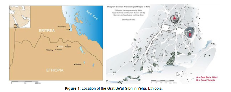
The building is located in Yeha, Ethiopia (Figure 1) and first came into the focus of archaeological investigations in 1906. The German Aksum Expedition documented architectural elements of the ruins that were visible above ground, including elements of the propylon and remains of the monumental sandstone door jambs. It was not until 1971 to 1973 that archaeological investigations at the structure were continued by F. Anfray [5]. He carried out extensive excavations for the first time, which mainly covered the entrance and areas behind the doorway. Although Anfray recognized the construction method of the walls made of quarry stone masonry and timbers, he was unable to grasp the outer limits of the structure and thus its extent on three sides.
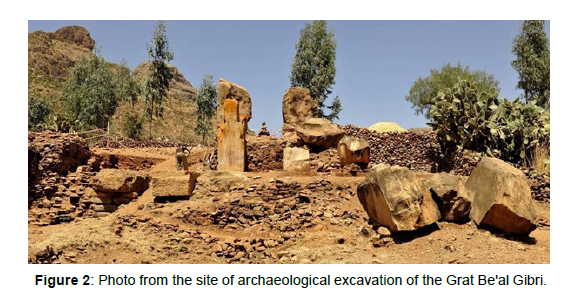
The work of the Ethiopian-German cooperation project initially began in 2009 with a cleaning and subsequent terrestrial 3D scan documentation of the surface of the rubble mound. Due to its location today in the midst of village development in Yeha, the site has been known for centuries and the rubble is continuously used as building material for the houses of Yeha's inhabitants. In some cases, families have settled on the ruined site. From 2009 until 2020, extensive excavations were carried out at the site, see (Figure 2). Now, it is possible not only to determine the extent of the structure, but also to make statements about its function and significance.
Building structure
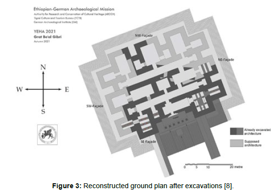
In this Section, the most important structural elements of the building are described. It should help to understand better the type of the structure in the historical context of the (ancient) time and geographical region under consideration. The building belongs to the type of palatial administrative building known mainly from South Arabia, for which there are several parallels, especially from the 1st millennium BC [6,7]. In contrast to ancient South Arabian sanctuaries, the interior of this type of building is divided into numerous rooms per story (Figure 3), with several stories being assumed in each case. The lower part of this type of building usually consists of a podium,which could be considered as a foundation, above which the actual floor building rises.
Figure 3: Reconstructed ground plan after excavations [8].
The 6 m high podium at the Grat Be'al Gibri in Yeha consists of a chamber wall system, whereby the chambers are filled with quarry stone material. The ground plan of the building, both the podium and the superstructure, is approximately square, with the four sides each divided by three tower-like projecting risalites. The fact that the corner risalites are assigned to the respective sides creates indented corners. The central risalit of the SE facade is designed as a monumental propylon with six monolithic pillars and thus marks the only verifiable entrance to date. Passing the propylon the entrant reaches a monumental doorway with door jambs. In front of the propylon is a wide flight of steps, which is bordered on both sides by two flanking walls.
The enormous thickness of the podium walls of 2.20 m and the walls above of 1.90 m together with the finding of a stairtower were the starting point for considerations that it must have been a multi-story building. This assumption is supported by the height [8].
Ff the pillars of the propylon marking the main entrance, which can be reconstructed as around 10 m on the basis of comparisons of proportions. Since the pillars were covered with architraves, on which in turn ceiling beams lay that connected the propylon with the main building, the latter must have been at least this height, i.e. about three stories high. Ancient rock and wall paintings depict multi-story buildings with a much higher number of stories [9,10].
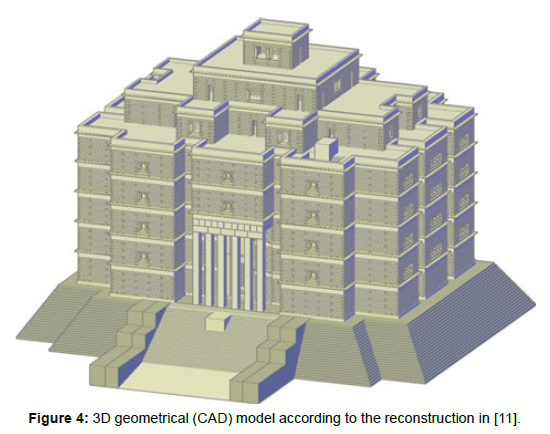
Since there are no further findings on the structure regarding the number of stories to be reconstructed, the building is shown in a first draft with five standard stories and above them three additional,recessed stories (Figure 4). These recessed upper three stories are also visible on rock paintings and murals in South Arabia [9,10]. Since the pillar propylon in the area of the front façade corresponds exactly to the shape of a central risalit both in its depth and width, the area above the propylon is modelled as a central risalit over two additional stories, as on the other sides of the façade. In the south-east of the building, remains of a surrounding stepped embankment made of stones, called glacis, have been preserved, which surrounded in the reconstruction the entire building for reasons of symmetry, except in the area of the monumental flight of steps [11].
Figure 4: 3D geometrical (CAD) model according to the reconstruction in [11].
Construction and materials
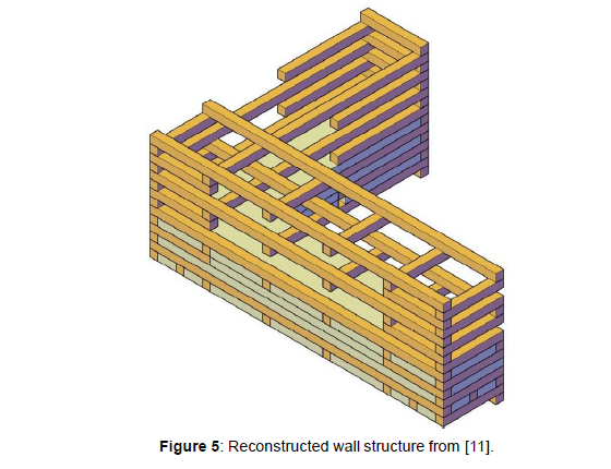
The archaeological-architectural investigations at the palace building Grat Be'al Gibri in Yeha, in cooperation with geologists and archaeobotanists, led to the identification of various construction materials used [12]. In the case of the walls, those below the ground floor can be distinguished from those above: For the walls of the podium serving as a foundation under the ground floor, quarry stones of locally available phonolite were used, which were masoned with a solid yellow clay mortar, also locally available, to form a quarry stone masonry. Neither continuously horizontal courses nor masonry shell structures can be observed, which is probably due to the polygonal fracture behavior of the phonolite stone. For the construction of the timber- reinforced walls above the podium, hardwoods (African Olive and Cordia Africana) were used in addition to the clay-mortared rubble stone masonry. The timbers, all axed into rectangular beams, were horizontally placed in the wall in longitudinal and transversal direction as shown in (Figure 5). Cross-sections of the beams of 0.21 m − 0.28 m can be reconstructed on the basis of beam imprints and cavities in the masonry, with the majority of the imprints having edge lengths of around 0.24 m. In the 3D CAD reconstruction, the latter dimension has been used as the edge length of all beams. The lowest timber layers always run transversely to the wall axis, followed by beams in the longitudinal direction. The two outer beams in the longitudinal axis are flush with the outer edge of the wall.
Figure 5: Reconstructed wall structure from [11].
Juniper (Juniperus procera) was used as ceiling-supporting columns within the rooms. The round or faceted columns, up to 0.40 m in diameter, stood in the rooms with spans of less than 2 m, which indicates enormous ceiling loads. The construction of the ceilings is not certain. It would be conceivable to have coffered or lath ceilings,of which there are at least late antique examples in South Arabia and East Africa [13,14]. Since only crumbled and heavily charred remains of beams have preserved in the debris of the rooms, it is difficult to determine the type of wood used for the ceilings. However, it seems that the ceilings consisted mainly of hardwoods (see above) and occasionally Juniper.
There is no archaeological evidence for the windows shown in the 3D reconstruction. It cannot be ruled out that - as shown there - the ground floor was without windows at all. At least for the upper floors windows can be assumed. In the absence of evidence, they are reconstructed as an imitation of known Aksumite windows, but again avoiding vertically arranged wooden elements.
All elements of the propylene and the subsequent door system are made of local sandstone elements. This was processed by stonemasons at great expense - until a final grinding was made. The propylene pillars were made of monoliths, probably also the door jambs. Both rest on massive bases, which were also made of sandstone. The large sandstone fragments found in the debris in front of the main entrance belong on the one hand to the architraves connecting the propylene pillars together and on the other hand to the ceiling beams above connecting the propylene with the main building [13,14].
3D finite element model
In this Section, the geometrical and architectural model of the building is transformed into a numerical simulation model within the finite element program ANSYS. At that, some simplifications have been taken as described below. The description is divided into geometrical parameters in Section 2.2.1, material parameters in Section 2.2.2, boundary conditions in Section 2.2.3 and model parameters in Section 2.2.4. The effects of the present simplifications on the obtained results are discussed later in Section 4.
Geometrical parameters
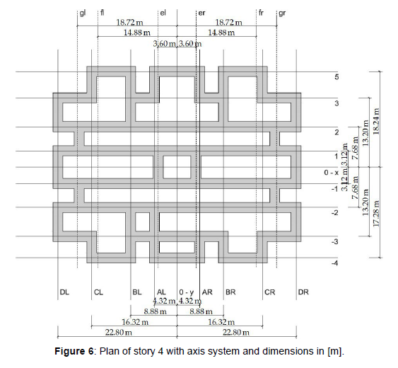
The floor plan of the palace Grat Be'al Gibri is assumed to be axisymmetric at each story. In (Figure 6), the floor plan at story 4 is shown with a defined global cartesian coordinate system. Instead of defining a global regular grid, local axes have been defined for each individual wall according to its longitudinal and transversal directions. The origin of the defined system is located in the intersection of the symmetry axes. The horizontal axes are indicated by numbers, positive above and negative below the global X-axis. Due to the symmetry, thaxes with the same absolute number have the same distance from the global X-axis. The vertical axes are marked with letters. The uppercase letters below the floor plan refer to the major vertical axes, the lowercase letters above the floor plan to the minor vertical axes of walls, which are only between the horizontal axes −2 and 2. The appended abbreviation in Figure 6 indicates whether the axis is left (L/l) or right (R/r) of the global Y-axis [15].
The outer dimensions are lX ×lY= 47.52 m × 37.44 m in story 1 to 5. As mentioned in Section 2.1.2, the thickness of the walls varies between t HW,0 = 2.16 m in story 0 to tHW,8 = 0.24 m in story 8. In the numerical model, the wall thickness is set constant to a value of tHW = 1.92 m enabling an easier finite element modeling. The influence of the reduced wall thickness in the upper stories is considered by appropriate factors in the associated dead loads, see later in Section 2.2.3. Furthermore, no windows or openings are modeled leading to continuous walls since no approved information about amount, position and size is available [16,17].
The CAD model of the building in Section 2.1.2 consists of eight stories over the podium (story 0). The podium has a height of ℎ0 = 6 m, the other stories have a clear height of ℎ1⋯8 = 3.36 m. The ceiling above each story has a thickness of tJT =0.96 m, leading to a total height lZ = ℎ0 + 8 ⋅ (ℎ1⋯8 + tJT) m = 40.56 m of the building
The propylon consists of six pillars, each with a rectangular cross section of pX ×p Y = 0.85 m × 0.95 and a length of pZ = 10.10 m. The original length of 10.50 m is shortened for simplicity due to mesh requirements in the finite element model. The clear distance between the pillars is aP = 1.00 m, except for the middle pillars, it is aP,34 = 1.25 m. Originally, the pillars have an offset of 0.25 m to the outer wall which is also not considered in the numerical model for simplicity. Above the pillars, the ceiling beam with a thickness of tCB = 0.96 m and the architrave with a thickness of tAP = 0.94 m are modeled as continuous volumes.
The following additional simplifications have been made in the numerical model compared to the CAD model, which concern secondary aspects and should not affect the primary results:
No consideration of stairs including the stair tower
No consideration of supporting columns inside the building
No consideration or enlargement of wall openings (e.g. for doors) Small adapting/shifting of wall axes
No consideration of decorative elements (e.g. corbels, attic)
No consideration of the chamber filling in the podium as well as the outer fill/staircase structure (Glacis)
Thus, a numerical model with a mostly regular finite element mesh, highest possible accuracy and acceptable costs for the computation could be created.
Material parameters
Phonolite and timber-clay-composite for walls
The rising walls of the building consist of clay-mortared, timberreinforced quarry stone masonry. Thus, it is a composite wall whose load-bearing behavior depends on the properties of its constituents and their interaction. Such composites can be modeled in detail with enormous computation cost if local interaction mechanisms are of interest. Alternatively, they can be homogenized if the focus is set onto the overall behavior. In this study, the wall structure has been homogenized for simplicity. The underlying material parameters of phonolite and the timber-clay-composite are described in the following [18].
For the material parameters of phonolite, it is only referred to phonolite rocks [12]. This allows the assumption that it is not a tuff, but for the sake of completeness this is not excluded. In the literature, no source could be found in which mechanical parameters for phonolite are listed, whereas values for plutonite, vulcanite’s and tuffs could be found in different sources, see (Table 1). Due to the classification of phonolite as vulcanite, these values can be regarded as appropriate limits until more precise findings are available. Based on (Table 1), the following minimum, mean and maximum values for the material parameters of phonolite have been used in the numerical simulations:
| rock | density | Young’s modulus | Compressive strength | tensile strength | flexural strength | ||
|---|---|---|---|---|---|---|---|
| 𝜌 [t⁄m3] | 𝐸 [GPa] | 𝑓c [MPa] | 𝑓t [MPa] | 𝑓f [MPa] | |||
| plutonites | |||||||
| granite/ syenite [15] | 2.60 − 2.80 | 40 − 80 | 160 − 240 | 10 − 20 | |||
| granite [16] | 80 − 300 | 10 − 40 | |||||
| granite [17] | 2.50 − 2.75 | 25 − 70 | 120 − 340 | 4 − 25 | |||
| granite [18] | 2.54 − 2.80 | 160 − 240 | |||||
| syenite [18] | 2.56 − 2.97 | 160 − 240 | |||||
| diorite/ gabbro [16] | 80 − 345 | 20 − 70 | |||||
| diorite [18] | 2.80 − 3.15 | 170 − 300 | |||||
| gabbro [18] | 2.80 − 3.15 | 170 − 300 | |||||
| gabbro [17] | 2.92 − 3.05 | 60 − 110 | 150 − 300 | 5 − 30 | |||
| diabase [17] | 2.50 − 2.75 | 30 − 90 | 120 − 250 | 6 − 13 | |||
| diabase [18] | 2.80 − 2.90 | 180 − 250 | |||||
| vulcanites | |||||||
| basalt/ nephelinite [16] | 160 − 400 | 20 − 65 | |||||
| basalt [18] | 2.74 − 3.20 | 250 − 400 | |||||
| basalt [17] | 2.75 − 3.00 | 20 − 110 | 80 − 400 | 6 − 30 | |||
| rhyolithe [18] | 2.55 − 2.80 | 180 − 300 | |||||
| rhyolithe [16] | 90 − 300 | 12 − 40 | |||||
| tuff rocks | |||||||
| tuff [15] | 1.30 − 2.00 | 30 − 80 | 5 − 25 | 1 − 4 | |||
| rhyolitic/ trachytic tuff [16] | 45 − 100 | 2 − 12 | |||||
| basaltic tuff/ -lava [16] | 25 − 220 | 5 − 20 | |||||
| basaltic lava [18] | 2.20 − 2.45 | 80 − 150 | |||||
Table 1:Compilation of the mechanical parameters of different plutonites, vulcanites and tuff rocks for the estimation of phonolite.
Density ��Ph = {1.30 ⋯ 2.25 ⋯ 3.20} t⁄m3,
Young’s modulus ��Ph = {20 ⋯ 65 ⋯ 110} GPa,
Compressive strength ��c,Ph = {5 ⋯ 202.5 ⋯ 400} MPa, (1)
Tensile strength ��t,Ph = {4 ⋯ 17 ⋯ 30} MPa and
Flexural strength ��f,Ph = {1 ⋯ 35.5 ⋯ 70} MPa.
The timber-clay-composite is simplified to one material with the following mean values based on [19]:
Density ��TC = 1.638 t⁄m3 and (2)
Compressive strength ��c,TC = 4.62 MPa.
Consequently, the material properties of the homogenized wall structure are defined as:
Density ��HW = (1 − ��TC) ⋅ ��Ph + ��TC ⋅ ��TC
with Timber-clay percentage ��TC = {0 ⋯ 1}, (3)
Young’s modulus ��HW = ��Ph and
Poisson’s ratio ��HW = 0.25 [20].
Juniper timber for ceilings
A density of ��JT = 0.6 t⁄m3 and values for the compressive and flexural strength for juniper timber can be found in [21]. However, juniper is a cypress species among the conifers. Since the ceiling is relevant in this study mainly due to its dead load, the mentioned value for the density is used, but strength values of an equivalent C24 softwood parallel to the fibre direction are applied (cf. [22]), leading to:
Density ��JT = 0.6 t⁄m3,
Young’s modulus ��JT = 11 GPa,
Poisson’s ratio ��JT = 0 (for simplicity), (4)
Compressive strength ��c,JT = 21 MPa,
Tensile strength ��t,JT = 14 MPa and
Flexural strength ��f,JT = 24 MPa.
Sandstone for pillar propylon
Local sandstone was used for the pillar propylon. Its material properties have been analyzed in a similar way as for the phonolite and have been summarized in (Table 2).
| rock | density | Young’s modulus | compressive strength | tensile strength | flexural strength |
|---|---|---|---|---|---|
| 𝜌 [t⁄m3] | 𝐸 [GPa] | 𝑓c [MPa] | 𝑓t [MPa] | 𝑓f [MPa] | |
| quartzitic sandstone | |||||
| [15] | 2.60 − 2.70 | 20 − 70 | 120 − 200 | 12 − 20 | |
| [16] | 60 − 290 | 7 − 33 | |||
| [18] | 2.60 − 2.65 | 120 − 200 | 12 − 20 | ||
| other sandstones | |||||
| [15] | 2.00 − 2.70 | 5 − 30 | 30 − 180 | 3 − 15 | |
| [16] | 15 − 190 | 3 − 18 | |||
| [17] | 2.10 − 2.50 | 15 − 50 | 20 − 250 | 20 − 25 | |
| [18] | 2.00 − 2.65 | 30 − 180 | |||
Table 2: Compilation of the mechanical parameters of different stones for the estimation of sandstone
Based on (Table 2), the following minimum, mean and maximum values for the material parameters of sandstone have been used in the numerical simulations:
density ��Ss = {2.00 ⋯ 2.35 ⋯ 2.70} t⁄m3,
Young’s modulus ��Ss = {5 ⋯ 37.5 ⋯ 70} GPa,
Poisson’s ratio ��Ss = 0.25 [20], (5)
compressive strength ��c,Ss = {15 ⋯ 152.5 ⋯ 290} MPa,
tensile strength ��t,Ss = {20 ⋯ 22.5 ⋯ 25} MPa and
flexural strength ��f,Ss = {3 ⋯ 18 ⋯ 33} MPa
2.2.3 Boundary conditions
Dirichlet boundary conditions
The focus of the present study is put on the superstructure of the palace. Therefore, the soil properties as well as the soil-structure interaction are not considered and the ground is assumed to be infinite stiff. Consequently, three one-dimensional spring elements, one in each global direction, have been placed on each node at ground level (�� = 0) and fixed on the other edge. The spring stiffness of ��V = 3 ⋅ 1016 N⁄m in global vertical ��-direction is extremely high leading to a nearly infinite stiff ground. The spring elements in global horizontal �� ��- and ��-direction are very weak with a stiffness of ��H = 30 N⁄m. Thus, horizontal displacements are not significantly restricted [19,20].
Neumann boundary conditions
All computations are performed under dead load of the overall structure. Any further loads (e.g. supplementary components like furnishings) are taken into account by increasing the dead load of all ceilings by a factor of ��JT = 1.5. As described in Section 2.2.1, the wall thickness at ��-th story is assumed as ��HW, = 0.24 ⋅ (9 − ��) m. Since the finite elements in the numerical model are defined with a constant thickness of ��HW = 1.92 m to enable regular meshes, the different wall thicknesses at ��-th story are considered by appropriate factors of ��HW, = (9 − ��)⁄8 in the associated dead loads.
Model parameters
The entire building is meshed by volume elements. The used higher order three- dimensional 20-node solid elements possess triquadratic shape functions, both for geometry and displacements. Each node has three translational degrees of freedom:
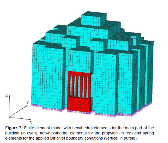
����, ���� and ����. Except of the propylon, hexahedral elements have been used with a mapped meshing technology. For the propylon, the mapped meshing would drastically increase the amount of elements and is therefore not appropriate. A free meshing technology with transitional pyramid and tetrahedral elements has been used alternatively. A performed benchmark test provided a reference edge length of the element of ��e = 1.68 m as suitable to keep desired accuracy of principal stresses at reasonable computational effort [21]. Thus, the developed finite element model contains 18654 hexahedral elements, 1460 non-hexahedral elements and 8889 spring elements see (Figure 7). In total, 113075 nodes and 26667 boundary conditions are present, leading to 312558 degrees of freedom.
Results
The results of representative numerical simulations of the building are shown and analyzed in this Section. They result from the geometrically and physically linear static analysis. The focus is on the displacement field �� = (���� ��, ����, ����) and on stresses at critical locations within the structure. The maximum first and the minimum third principal stress (��1,max, ��3,min) are compared regarding various input parameters. Especially for some material parameters, an extremely large uncertainty has been detected in Section 2.2.2. For simplicity, the timber-clay percentage is set to ��TC = 0 in all simulations. A study concerning the heterogeneous wall structure is essential, but beyond the scope of this paper.
The results using mean values for density and Young's modulus for phonolite as well as for sandstone are given in Section 3.1. In Section 3.2, the variation of the densities is conducted and analyzed. Furthermore, the Young's modulus is varied in Section 3.3.
Structural assessment by use of mean values for material parameters
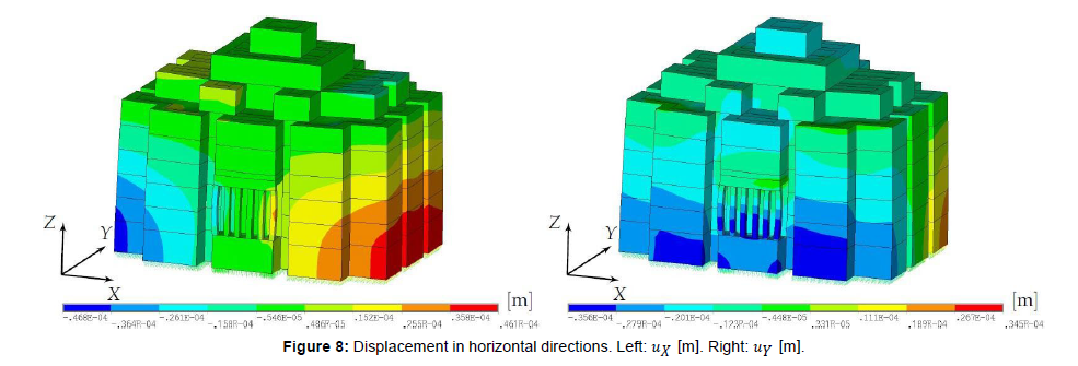
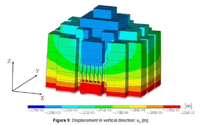
The used mean values for the numerical simulation are listed in (Table 3). The resulting displacement field �� is displayed in (Figure 8) and (Figure 9).
| material | density | Young’s modulus |
|---|---|---|
| 𝜌∙ [t⁄m3] | 𝐸∙ [GPa] | |
| wall (100 % phonolite ∙Ph) | 2.25 | 65 |
| propylon (sandstone ∙Ss) | 2.35 | 37.5 |
Table 3: Mean values for material parameters with extreme uncertainty. All other material parameters are given in Section 2.2.2.
The maximum absolute horizontal displacement occurs at ground level with a value of ��H,max = 0.0468 mm. The displacement values ���� and ���� under dead load are, as excepted, very small and nearly double symmetrical. Also the vertical displacements ���� are small and nearly double symmetrical with a maximum absolute value on the top of ��V,max = ����,max = 0.175 mm. It is worth mentioning that the homogenized material properties generally lead to a higher stiffness of the structure and smaller displacements compared to that with inhomogeneous material. Another reason for small displacements is neglecting soil and structural settlements, so that the obtained displacements represent only compressive deformations within the structure [22, 23].
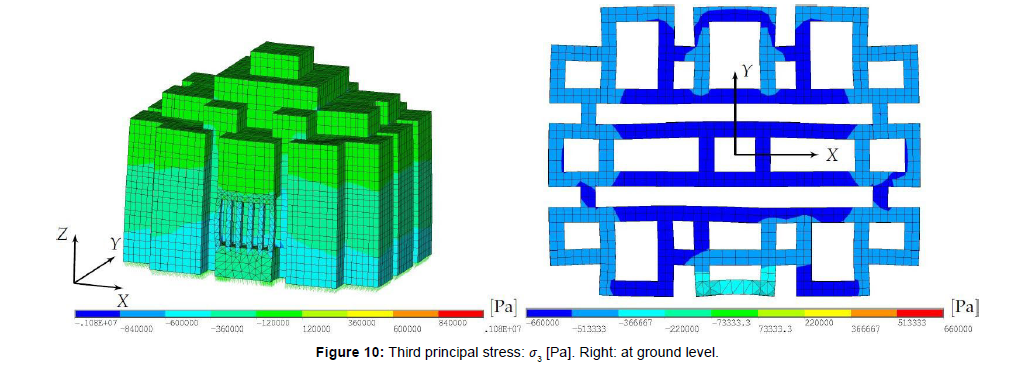
The stress state of the structure can be well characterized by the principal stresses in each element. The third principal stress ��3, whichcorresponds mainly to the vertical compressive stress ����, is depicted in (Figure 10).
The minimum value of ��3,min, Sing = −1.08 MPa is located between story 1 and 0 caused by a geometrical singularity. Excluding this region, the minimum value of ��3,min,Unsc = −0.66 MPa is, as assumed, at ground level in the wall, see Figure 10 (Right). The stress value has to be scaled back to the original wall thickness at story 0 (see Section 2.2.1):
��HW = �� ⋅ ��HW = (−0.66 MPa) ⋅ 1.92 m = −0.59 MPa
. 3,min 3,min,Unsc ��HW,0 2.16 m (6)
The principal stresses ��1 ≥ ��2 correspond mainly to stresses in the horizontal ��-�� plane. The maximum value of ��1,max,Sing = 0.51 MPa is located at the bottom of the pillars caused by geometrical singularities and mesh irregularities in this region. In general, the values of the first principal stress ��1 should be verified by finer models also considering the heterogeneous wall structure. This investigation is beyond the scope of this study.
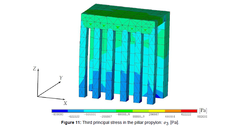
In the pillar propylon made of sandstone, the minimum third principal stress is at the bottom of the second pillar from right (Figure 11) with a value of
��Ss = −0.80 MPa.
3,min (7)
For the sake of completeness, the maximum first and the minimum third principal stresses in the ceilings are determined to
��JT
1,max = 0.18 MPa and (8)
��JT
3,min = −0.20 MPa.
The load-bearing behavior of the ceilings have not been analyzed further here because it requires a higher level of detailing in the model due to supporting mid- columns in each room and further constructional particulars.
Structural assessment under varied density
Since material properties like density and Young's modulus of the construction materials of the ancient palace are uncertain parameters, the structural simulations have been performed in addition to the mean values also for the identified minimum and maximum values of the relevant properties. It should limit the possible range of output parameters to be considered for the result interpretation. First, the material densities have been taken by their minimum and maximum values under constant mean values of the corresponding Young's moduli. Consequently the maximum density corresponds to stress values representing an upper bound.
The material parameters are given in Section 2.2.2. First, only the density of the wall (phonolite) ��Ph is varied with the values given in Equation (1) and the obtained stresses are compared to the minimum compressive strength values of sandstone ��c,Ss,min, phonolite ��c,Ph,min and timber-clay composite ��c,TC,min. The results aregivenin (Figure 12) (Left). In each group, the left column represents the calculated principal third stress with the minimum density, whereas the right column represents the stress computed with the maximum density. The middle column shows the result for the mean density described in Section 3.1. The minimum compressive strength values are displayed as horizontal lines.
The absolute values of the third principal stresses are smaller than the minimum compressive strength which belongs to the timber-clay composite with ��c,TC,min = 4.62 MPa. Therefore, the ultimate carrying capacity of materials cannot be reached under any density value from the considered ones, and no failure is to be expected.
The same variation has been done for the density of the sandstone ��Ss (see also Equation (5)). The results are presented in (Figure 12) (Right). As expected, the density of the sandstone does not influence the third principal stress for the considered point at ground level in the wall. The stress at the point in the pillar is more influenced by the variation but in comparison to (Figure 12) (Left) it can be seen that the density of the wall is the dominant variable.
Structural assessment under varied Young's moduli
The same procedure as in Section 3.2 has been done for the Young's modulus of the phonolite and the sandstone with the minimum and maximum values according to Equation (1) and Equation (5) while the other values have been kept constant. The results are shown in (Figure 13). As for the variation of the density, the absolute third principal stresses are significantly smaller than the minimum values of the compressive strength of the involved materials.
The value ��HW occurred close enough to the propylon. Consequently, a change in Young's modulus of the sandstone ��Ss influences the stress (compare Figure 13 (Right)). However, the difference is small, whereas a change in Young's modulus of the phonolite ��Ph does not change the stress at all.
A different behavior has to be noted for the stress at the bottom of the pillar. For an increase of Young's modulus of the sandstone ��Ss, the compressive stresses increase while for an increase of Young's modulus of phonolite ��Ph the stresses decrease. Even though the stress values |��Ss | significantly depend on the Young's moduli, the maximum values are always smaller than the minimum value of the compressive strength of sandstone of ��c,Ss,min = 15 MPa.
Discussion
Several assumptions and simplifications on materials and construction of the palace building Grat Be'al Gibri have been made during this preliminary study. The first aspect concerns the composition of the whole building. Although only the ground part of the building was available after excavation, the same ground plan with the same walls has been assumed to be valid for five regular stories above the ground level (see Figure 3). The real amount of stories, their actual ground plans and the wall thickness remain uncertain parameters. Three additional stories with reduced ground plan on the top of the building (Figure 4) contain several uncertainties as well but are not crucial for the overall structural performance. The ground plan has been further slightly simplified by neglecting the wall openings and small offsets, as can be seen by comparing Figure 3 and Figure 6. They have been estimated to be unable to critically influence the load-bearing capacity of the whole structure, but would require major additional effort for detailed modeling.
The second main simplification concerns the material homogenization of the timber-laced masonry walls. This composite structure requires many specific aspects to be modeled in detail, like material properties of individual components timber, quarry stones and clay mortar, as well as their proportion, deformation mechanisms and interaction. Instead of dealing with a large amount of specific uncertain parameters and their influence on the simulation results, a rational decision has been made to homogenize the composite material and estimate its properties like Young’s modulus and Poisson’s ratio from the literature within a physically meaningful range of values. In such a way, the amount of uncertainties could be still reasonably handled.
The soil properties and the soil-structure interaction have not been considered in the present study. That is the next simplification made in order to avoid an additional uncertainty factor and significant simulation effort. The foundation of the building has been assumed as fixed. Whether this simplification could lead to an advantageous or disadvantageous structural performance cannot be answered in advance, without soil investigation on site. Unfortunately, the information on mechanical properties of the local soil is currently unavailable.
In addition, the ceiling construction has been simplified by ignoring the mid-columns in each room and homogenizing the slab construction, since the ceiling performance should become a matter of the next detailed study.
The further simplification has been made that the building is loaded mainly by the self-weight, since this parameter can be estimated quite well from the geometrical dimensions of structural members and their density. The wind load is almost irrelevant for such a massive structure. The live loads from persons, equipment and storage are static in nature and can be taken in the first step as a portion of the dead load like in the present study. Dynamic loads, for example by the earthquakes, are out of the scope of the present study.
Finally, the staircase tower has been excluded from the model which does not influence the structural behavior since it is independent of the remaining building.
The structural performance has been decided to assess by means of principal stresses in critical components and structural deformations as a whole. It is consistent with the assumptions made above and can lead to the first reasonable estimations. The principal stresses, even if they are determined within the linear elastic analysis, can show how far the stress state is from the critical one or from the limits of the loadbearing capacity.
The obtained results allow the following general conclusions. The principal stresses are mainly compressive ones resulting from the selfweight of the structure. The maximum magnitude of ��3 = 1.08 MPa is far below the minimum compressive strength for masonry ��c,TC,min = 4.62 MPa. Even if the live load of the building is set equal to the dead load, i.e. the dead load is doubled, the compressive stress lies still far below the relevant strength. Whether the same compressive stress (bearing pressure) is critical for the soil underneath the building, cannot be answered without a soil inspection and characterization on site.
Since the tensile strength in masonry is generally quite low, it is usually not considered as a relevant design characteristics in civil engineering. High tensile stresses can lead to tensile or shear cracks in masonry. Some constructional measures should be taken to carry tensile stresses, for example, reinforcing. The maximum tensile stress ��1 = 0.51 MPa in the palace construction is determined to be directed in the horizontal �� ��-�� plane. The horizontal placement of timber beams seems to fulfill just this reinforcing function with respect to horizontal tensile stresses. For comparison purposes only, the tensile strength of ordinary low-strength concrete is about ��ctm = 1.60 MPa and that of clay is about 0.05 MPa. The tensile stresses in the present case are between these values, so the crack appearance seems to be probable and the reinforcement reasonable.
In this context, it is worth mentioning that the maximum compressive and tensile stresses occur in the middle part of the building. The outer perimeter is composed of three closed cells along each side of the ground plan (Figure 3), which lead to the tower-like construction for each cell over the height. It is likely that the ground plan with outer cells was selected similar to the honeycomb structures. The advantage of that choice is now numerically approved for the stresses. The stresses in these cells are essentially smaller compared to those in the inner walls in Figure 10 (Right). Besides, the stability of the connected tower group would be essentially higher than that of a building with smooth and long walls, albeit quite thick walls.
The present virtual building possesses five regular stories. Summarizing the obtained numerical results and taking into account involved uncertainties, it can still be concluded that the original building could certainly have several stories. Whether their amount is smaller or larger than five, needs additional investigation, including the soil and the composite structure in detail.
Some of the archaeological questions about the building cannot be answered yet; they should be a matter of further investigation. Among them, the role of the timber beams in the composite wall structure including their interaction with stones and clay, the structural performance of ceilings under local bending and their bearing capacity, the soil-structure interaction and its influence on the global deformation and load- bearing capacity, the influence of structural details like openings and so on. The answers to these questions require multi-scale modeling techniques and more information about specific features of used materials and members. Since this information is very limited or even unavailable, advanced non-deterministic simulation methods should be applied to properly quantify uncertainty and reduce it by use of special laboratory experiments on representative reference constructions as well as measurements on site. The uncertainty quantification was the topic of the DFG Priority Program "Polymorphic uncertainty modelling for the numerical design of structures – SPP 1886". The authors are going to apply the corresponding experience with probabilistic and non-probabilistic simulation methods (cf. [23,24]) onto the virtual reconstruction of the palace building in Yeha and perform the above mentioned investigation steps in the near future.
Acknowledgement
The archaeological and building historical investigations within the Ethiopian-German cooperation-project in Yeha are funded since 2016 by the DFG (Deutsche Forschungsgemeinschaft); grant number: GE 1980/4-1.
References
- Gerlach I (2013) Cultural Contacts between South Arabia and Tigray (Ethiopia) during the early 1st millennium BC. Results of the Ethiopian-German Cooperation Project in Yeha. Zeitschrift für Orient-Archäologie 6: 252-275.
- Schnelle M (2021) Observations on architectural features from the early 1st millennium BC in South Arabia and East Africa. In Contacts between South Arabia and the Horn of Africa, from the Bronze Age to Islam. In Honor of Rémy Audouin, Toulouse 145-158.
- Darles C (2010) L’emploi du bois dans l’architecture du Yémen antique. Proceedings of the Seminar for Arabian Studies 40: 149-160.
- Schnelle M (2019) Timber-frame Architecture on Both Sides of the Red Sea from the Early First Millennium BCE. Recent Investigations of the German Archaeological Institute in South Arabia and Northern Ethiopia. In Stories of Globalisation; Manzo A, Zazzaro C and D J de Falco Hrsg Leiden/Boston 95-118.
- Anfray F (1995) Yeha Les ruines de Grat Be’al Gebri. Recherches archéologiques. Rassegna di Studi Etiopici 39: 5-23.
- Japp S (2019) Edifices on podia with courtyards and framing wings – a specific architectural structure in South Arabia. In Ancient South Arabia: Kingdoms, Tribes and Traders. Hatke G and Ruzicka R (Hrsg.): Cambridge 181–212.
- Loreto R (2011) L’architettura domestica e i palazzi reali di epoca sud arabica nello Yemen pre-islamico : (VII. sec. a. C. - VI. sec. d. C.).
- Gerlach I (2014) Yeha, Äthiopien, Die Arbeiten der Jahre 2012 und 2013 Außenstelle Sana’a der Orient- Abteilung des DAI.
- Al-Ansari (2011) AMT, Qaryat al-Faw. In Roads of Arabia. The Archaeological Treasures of Saudi Arabia. Wasmuth Verlag Tübingen/Berlin 150-167.
- Al-SalamI, MA (2012) Die Felsmalereien von ̆Garf al-Yah ̄ud im zentraljemenitischen Hochland. Neue Informationen zur Palastarchitektur im vorislamischen Arabien. In Archäologische Berichte aus dem Yemen; Reichert Verlag: Wiesbaden 91–101.
- Schnelle M (2013) Grat Be‘al Gebri - bauhistorische Untersuchungen an einem Monumentalbau des frühen 1. Jahrtausends v. Chr. im äthiopischen Hochland. In architectura Zeitschrift für Geschichte der Baukunst; Deutscher Kunstverlag Berlin München: Berlin 89-112.
- Krencker D (1913) Die Klosterkirche von Debra Damo. In Ältere Denkmäler Nordabessiniens; Reimer Verlag: Berlin 1913 Vol 2 Deutsche Aksum-Expedition 168–194.
- Bruckner H, Schneider U ((2014) 6 E Baustoffe und ihre Eigenschaften. In Schneider Bautabellen für Ingenieure mit Berechnungshinweisen und Beispielen;
- Siedel H , Arten, Klassifizierung, technische Eigenschaften und Kennwerte (2004) In Mauerwerk-Kalender; Ernst & Sohn Verlag für Architektur und technische Wissenschaften GmbH: Berlin chapter AI 5-29.
- Von Soos P, Engel J (2017) Eigenschaften von Boden und Fels – ihre Ermittlung im Labor. In Karl Josef Witt (Hrsg.), GRUNDBAU-TASCHENBUCH Teil 1: Geotechnische Grundlagen; Wilhelm Ernst & Sohn,
- Jäger W, Marzahn G (2010) Mauerwerk Bemessung nach DIN 1053-100; Ernst & Sohn Verlag für Architektur und technische Wissenschaften GmbH & Co. KG: Berlin.
- Stefanidou M, Papayianni I, Pachta V (2015) Analysis and characterization of Roman and Byzantine firedbricks from Greece. Material and Structures 48: 2251-2260.
- Prinz H, Strauß R (2018) Ingenieurgeologie; Springer Spektrum Springer-Verlag GmbH Deutschland.
- http://www.holzwurm-page.de/holzarten/holzart/zeder.htm
- https://shop.reguvis.de/online-ausgabe/bautabellen-digital-bautabellen-fuer-ingenieure/
- Drieschner M, Petryna Y, Gruhlke R, Eigel M, Hömberg D (2020) Comparison of various uncertainty models with experimental investigations regarding the failure of plates with holes.
- Drieschner M, Petryna Y, Freitag S, Edler P (2021) Decision making and design in structural engineering problems under polymorphic uncertainty. Engineering Structures 231: 111649.
Citation: Drieschner M, Wilhelm S, Petryna Y, Schnelle M, Gerlach I (2023)Preliminary Structural Analysis for the Archaeological Reconstruction of theAncient Palace Grat Be'al Gibri in Yeha, Ethiopia. J Archit Eng Tech 12: 337. DOI: 10.4172/2168-9717.1000337
Copyright: © 2023 Drieschner M. This is an open-access article distributed underthe terms of the Creative Commons Attribution License, which permits unrestricteduse, distribution, and reproduction in any medium, provided the original author andsource are credited.
Share This Article
Recommended Journals
Open Access Journals
Article Tools
Article Usage
- Total views: 2262
- [From(publication date): 0-2023 - Apr 17, 2025]
- Breakdown by view type
- HTML page views: 1995
- PDF downloads: 267

