Research Article Open Access
Power Divider with the Combination of Bagley Polygon Power Divider and Equal Split Wilkinson Power Divider
Govind Singh Thakur*, Prashant Gupta, P. K. Singhal and Vandana Vikas ThakareDepartment of electronics, Madhav Institute of Technology and Science Gwalior MP, India
- *Corresponding Author:
- Govind Singh Thakur
Department of electronics, Madhav Institute of Technology and Science Gwalior MP, India
E-mail: govindsirt@gmail.com
Visit for more related articles at International Journal of Advance Innovations, Thoughts & Ideas
Abstract
A 6-way power divider with the combination of Bagley polygon power divider, Wilkinson power divider and defected ground structure are proposed in this specific work. A 100 ohm isolation resistor is used to achieve good isolation in Wilkinson power divider. The proposed configuration having, 2-section of 3-way triangular shape Bagley polygon power divider connected with the output of 2-way Wilkinson power divider. Parameters of the proposed configuration are calculated at the centre frequency of 1.5 GHz. For verification the proposed design is fabricated with the dielectric constant of 4.4 and loss tangent of 0.02. The result is having triple frequency response at 1GHz, 1.5GHz and 2GHz frequency with a gap of 0.5GHz. Return loss at all the ports below -10 dB, transmission coefficient above -7.5 dB and isolation among output ports are better than -10 dB is achieved. Measured results by spectrum analyzer are compared with simulated results by computer simulation technology microwave studio and found satisfactory.
Keywords
Bagley polygon power divider, computer simulation technology microwave studio, defected ground structure, SMA (submarine version A) connector, spectrum analyzer, Wilkinson power divider.
Introduction
Power divider and combiner are very important in the microwave and millimetre wave systems. It is used to distribute input power to more than two output ports. They are having application in the field of antenna, amplifier, wireless communication system, mixer, phase shifter and measurement systems. In these dividers Wilkinson power divider, Gysel power divider and Bagley power divider are most important topic for research in recent years [1]. An N-way Wilkinson power divider is of two types, equal split and unequal split depend on power level at the output. The original Wilkinson power divider developed by Wilkinson, consist of two quarter wavelength line and uses isolation resistor at the output [2]. Compared to other power divider Bagley polygon power divider did not uses any isolation register, and can be easily extended to any number of output ports [3]. In the work dual band, multi band Wilkinson power dividers [4-6], Bagley polygon power divider [7] has been considered.
In the proposed design a triple frequency power divider is made with the help of 2-way equal split Wilkinson power divider, 3-way triangular shape Bagley polygon power divider and defected ground structure (DGS) (etched circle in ground plane). The proposed design is simulated, by CST microwave studio using transient solver [8], and tested by spectrum analyzer in frequency range 0 to 3 GHz.
Design Methodology
The proposed configuration of the power divider with single input port and six output port is shown in figure 1. Two section of triangular Bagley power divider with the combination of Wilkinson power divider is
proposed. Single isolation register is use for the equal power division at the output as shown in figure 1. For
effective study single section of 3-way triangular shape Bagley polygon power divider is proposed. It has
single input and three output port and it has three arms with impedance of  ohm as shown in figure2. To
accomplish the design, following electromagnetic equations used for the calculation of length and width are
given belowThe empirical formula for the calculation of width to length ratio is given by equation (1) [9]
ohm as shown in figure2. To
accomplish the design, following electromagnetic equations used for the calculation of length and width are
given belowThe empirical formula for the calculation of width to length ratio is given by equation (1) [9]

Figure 1: Proposed configuration of power divider

Figure 2: A 3-way Bagley polygon power divider
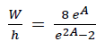 (1)
(1)
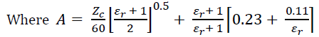 (2)
(2)
Also Zc = Z0= 50 Ω, εr (dielectric constant) =4.4, W = width, h = height of dielectric that is taken as 1.6 mm with loss tangent of 0.02.
Guided Wavelength is calculated by equation (3) [9].
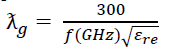 (3)
(3)
Where εre = Effective dielectric constant, f = 1.5 GHz
Electrical Length is calculated by equation (4) [9]
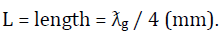 (4)
(4)
Effective dielectric constant of dielectric material is given by equation (5) and equation (6) [9].
For W/h ≤ 1,
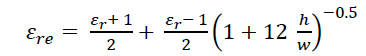 (5)
(5)
For W/h>1
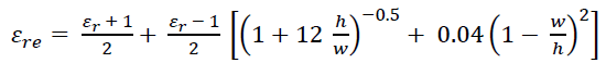 (6)
(6)
Where w/h is calculated using equation (1). Values obtain after calculation is given in table 1.

Table 1: Values of the Length and Width of the Configuration.
Results
Single Section of Bagley Polygon Power Divider
Single section of Bagley power divider is test first at the centre frequency of 1.5 GHz. The return loss is measured at all ports (S11, S22, S33 and S44), by terminating all the ports except one of them with the matched load (in present case 50 ohm). The fabricated PCB (printed circuit board) Layout shown in figure 3 and Measurement setup for S11 is shown in figure 4. Return loss at port 1 (S11) works in the centre frequency of 1.5 GHz with the bandwidth of nearly 1.1 GHz Shows in figure 5. The graph ranges between -15 to -20 dB. S22, S33 and S44 are also shown in the figure 6 and figure 7, which are having return loss below - 10 dB. It shows perfect matching at all ports.

Figure 3: Fabricated PCB layout of the Bagley power divider.

Figure 4: Measurement setup for the calculation of S11.

Figure 5: Simulated and measured return loss at port 1.

Figure 6: Simulated and measured return loss at port 2 and port3.

Figure 7: Simulated and measured return loss at port 4.
The transmission parameters of the single Section of the Bagley power divider is calculated by terminating all port except input and output port with match load. The results show proper working of the single section of the Bagley power divider at frequency of 1.5 GHz. The result having, transmission coefficient ranges between -5dB to -6dB. The graph of the transmission parameters are shown in figure 8 and figure 9.

Figure 8: Simulated and measured transmission coefficient from port 1 to port 2 and port 3.

Figure 9: Simulated and measured transmission coefficient at port 1 to port 4.
Dual Section Bagley Power Divider with the Help of Wilkinson Power Divider
In the proposed dual section Bagley Power Divider return loss at all ports calculated as in single section Bagley power divider. The PCB Layout shown in figure 10 and measurement setup for the calculation of S11 is shown in figure 11. In case of S11 it is having triple frequency response at 1GHz, 1.5GHz, 2GHz frequency, with the return loss of -33.162dB, -23.315dB, -22.095dB respectively shown in figure 12. The proposed triple frequency configuration can be used as wide band divider in the frequency range 0.88GHz to 2.11GHz (bandwidth of 1.23 GHz). Return loss at the remaining ports ranges between -10dB to -30dB is also shown in figure 13 (S22, S33, S55 and S66) and figure 14 (S44 and S77).

Figure 10: PCB layout of the proposed configuration.

Figure 11: Measurement setup for the calculation of return loss at port 1.

Figure 12: Simulated and measured return loss at port 1.

Figure 13: Simulated and measured return loss at the port 2, port 3, port 5 and port 6.

Figure 14: Simulated and measured Return loss at port 4 and port 7.
The transmission parameters of dual section Bagley power divider are calculated by terminating all port except input and output port with match load (50 ohm resistance). The transmission coefficient ranges between -7dB to -8dB. Results of transmission coefficients are shown in figure 15 and figure 16.

Figure 15: Simulated and measured transmission coefficient from port1 to port 2, port 3, port 5 and 6.

Figure 16: Simulated and measured Transmission coefficient from port1 to port 4 and port 7.
Conclusion & Future Work
This paper presents the analysis and design of general multi frequency power divider. The proposed dual section and single section of the Bagley power divider were designed, simulated, fabricated and measured. The results of the designed power divider show the validity of the proposed design procedure and proved the multi frequency and wide band nature. Good matching at input/output ports and good isolation among output ports were achieved.
References
- David M. Pozar, “Microwave Engineering”, 3rd Ed., John Wiley & Sons Inc., New York, 2005.
- Wilkinson, E., “An N-way hybrid power divider," IRE Trans. Microw. Theory Tech., Vol. 8, No. 1, 116- 118, 1960.
- Lula bai, Shen Zhang and Kai huang “ A novel Dual Band multi way power divider Using coupled lines” Progress In Electromagnetics Research C, Vol. 37, 115-129, 2013.
- A. M. Qaroot and N. I. Dib “General Design Of N-Way Multi-Frequency Unequal Split Wilkinson Power Divider Using Transmission Line Transformers” Progress In Electromagnetics Research C, Vol. 14, 115-129,
- B. Li, X. Wu and N. Yang” Dual-Band Equal/Unequal Wilkinson Power Dividers Based On Coupled- Line Section With Short-Circuited Stub” Progress In Electromagnetics Research, Vol. 111, 163-178, 2011
- X. Li, Y.J. Yang, L. Yang, S.-X. Gong, X. Tao, Y. GaoK. Ma and X.-L. Liu “A Novel Design Of Dual-Band Unequal Wilkinson Power Divider” Progress In Electromagnetics Research C, Vol. 12, 93-100, 2010
- A. Qaroot, K. Shamaileh, and N. Dib “Design And Analysis Of Dual-Frequency Modified 3-Way Bagley Power Dividers” Progress In Electromagnetics Research C, Vol. 20, 67-81, 2011
- CST (Computer Simulation Technology) Microwave Studio 2010.
- Jia-Sheng Hong, M. J. Lancaste “Microstrip filters for RF / Microwave Application” A Wiley- Interscience Publivatio.
Relevant Topics
- Advance Techniques in cancer treatments
- Advanced Techniques in Rehabilitation
- Artificial Intelligence
- Blockchain Technology
- Diabetes care
- Digital Transformation
- Innovations & Tends in Pharma
- Innovations in Diagnosis & Treatment
- Innovations in Immunology
- Innovations in Neuroscience
- Innovations in ophthalmology
- Life Science and Brain research
- Machine Learning
- New inventions & Patents
- Quantum Computing
Recommended Journals
Article Tools
Article Usage
- Total views: 16333
- [From(publication date):
May-2013 - Apr 04, 2025] - Breakdown by view type
- HTML page views : 11491
- PDF downloads : 4842