Numerical Investigation of a Coupled Passive Cooling System Earth to Air Heat Exchange and Solar Chimney in Hot Arid Zone
Received: 08-Feb-2018 / Accepted Date: 19-Feb-2018 / Published Date: 23-Feb-2018 DOI: 10.4172/2576-1463.1000188
Abstract
The papers present a theoretical work on coupled passive cooling system, earth-to air heat exchange and high inertia well insulated solar chimney attached to the building south wall with direct outlet. The system was supposed to be used for summer cooling in hot arid zone in Ghardaia city in the south of Algeria. An investigation on the effects of the systems variable parameters on the cooling efficiency were carried out for hot summer days, these variable parameters were; Pipe: buried depth, cross section, length, disposition, number, and inlet outlet cross sections. Chimney: top and bottom sections, orientation, height, inlet outlet sections and positions, chimney wall insulation and thermal inertia.
A numerical simulation carried out during summer days for two similar well insulated buildings, the first one with the above mentioned passive cooling system and the second without any passive features as a reference building, the buildings were assumed located in Ghardaia hot arid climate in the south of Algeria, in order to optimize the above cited variable parameters for the two coupled passive systems.
Keywords: Coupled systems; Solar chimney; Geothermal cooling; Hot arid climate; Soil temperature
Nomenclature
as: Soil surface temperature amplitude variation, °C
Ag: Glass area m2
Aab: Absorber Area m2
Ao: Outlet cross section m2
Ai: Inlet cross section m2
Ca: Air specific heat J/kgK
cach: Air in chimney specific heat J/kgK
hcg: Convective heat transfer glass to chimney air W/m2K
hr-ab: Radiation coefficient between glass and absorber W/m2K
hr;g-sky: Radiation coefficient between glass and sky W/m2K
hwind: Outside convective transfer W/m2K
etube: Tube thickness m
g: Gravitational constant m/s2
I: Global solar radiations W
L: Length m
Lch: Chimney height m
m: Air flow rate mass kg/s
Q: Heat flow W
R: Thermal resistance m2/W°K
t: Day of year
T: Temperature °C
Tai: Inside air temperature °C
Tae: Outside air temperature °C
Tsoil: Soil temperature °C
Tmean: Mean annual temperature, °C
t0: Day of maximum surface temperature (i.e. 250)
Ug: Glass transmittance W/m2°K
Wv: Wind velocity m/s
z: Depth from soil surface m
Greek Letters
α: The soil thermal diffusivity m2/day
αab: Absorber absorptivity %
αg: Glass absorptivity %
λ: Thermal conductivity, W/mK.
ρ: Soil density, kg/m3
ρach: Chimney air density kg/m
δ: Heat pernitration depth m
τg: Glass transmissivity %
ω: Annual temperature frequency, rad/day
Introduction
Building ventilation and air conditioning active systems are responsible for about half of energy consumed in the buildings [1], especially buildings in Ghardaia in the south of Algeria with hot arid climate, where the cooling season is more than seven months from May till end of October and the maximum outdoor temperature reached 50°C under shade. The use of active cooling features day and night in this area for such a long period rise the non-renewable energy consummation by 9% in 2013 in this region. The electrical energy consummation by residential buildings presented 62% of all electrical energy produced in 2013 [2], that due to high demographical growth and residential building demands. The built houses in Sahara region don’t respect the building thermal code integration with the local climate and thermal insulation. Effective integration of passive systems for cooling into the buildings can significantively reduce the air conditioning demand maintaining thermal comfort [3] Passive systems are like geothermal (earth to air heat exchanger) for cooling and solar chimney for ventilating. In recent years many researches were carried out in many places around the world to investigate the efficiency of such systems, Benhammou et al. [4] tested the performance of an earth to air heat exchanger assisted by wind tower for passive cooling in hot arid climate by developing an analytical model, during summer days in July the hottest month an efficiency of 66.78% was found. An investigation of geothermal passive cooling in arid climate was carried by Belatrache et al. [5] using a numerical analysis, a maximum daily cooling capacity potential of 1.73 kw/h and a maximum outside inside temperature difference of 20.7°C were recorded in July. An experimental and numerical simulation were carried out on an earth to air heat exchanger for cooling for residential building in hot semi-arid climate by Khabbaz et al. [6], they tested one and three pipes system, the temperature tropes were 19.5°C and 18.3°C, and the cooling capacities were 58 and 55 w/m2 for 1 and 3 Pipes respectively. Yuebin et al. [7] investigated a coupled cooling passive system, geothermal and detached solar chimney attached to the building by solar collector, three different testes were carried out for 43 days, using solar chimney for ventilation for the first period, mechanical ventilation for the second and back to chimney ventilation for the third period. Their results show that the indoor air conditioning was more stable and less soil saturations by passive solar chimney ventilation.
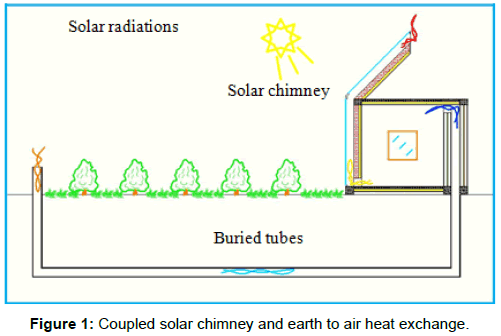
The present paper focus on studying a coupled earth to air exchanger and high inertia well insulated solar chimney attached to the building with direct outlet as shown Figure 1. A numerical simulation carried out for two similar well insulated buildings the first one with passive cooling system and the second without any passive features as a reference building, the buildings were assumed located in Ghardaia hot arid climate in the south of Algeria.
Experimental
System modeling
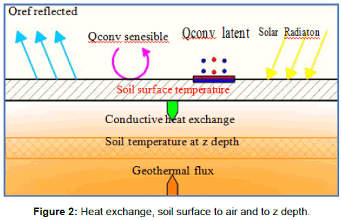
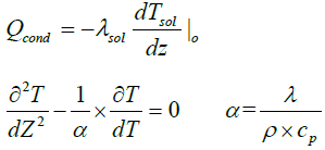
Soil temperature: The soil temperature at 2 m to 3 m depth present small fluctuations during cooling period almost constant [8], and this temperature is less than the outside air temperature. The soil temperature depends on; Soil: type, conductivity, density, thermal capacity, humidity ratio, reflectivity and depth. Outside climatic conditions: air temperature, solar radiation, and wind speed. The average soil temperature can be calculated as function of average soil surface temperature, average outside air temperature, average solar radiations and average wind speed in the studied region. The heat exchange of soil surface shown in Figure 2 is given by [9];

 (1)
(1)
 (2)
(2)
For z=0, soil surface temperature at time t
 (3)
(3)
For Z = ∞ , at deep depth the soil temperature equal the mean temperature for time t

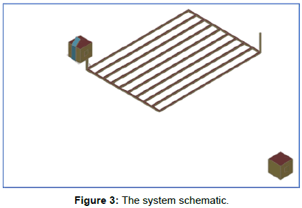
Earth to air heat exchange: The tubes were considered lay into soil in horizontal plan surface with constant distances from each other and had a single inlet and outlet air as shown in Figure 3. Tubes have the same properties and the soil was considered homogeneous, the heat exchange between soil and inside tubes air can be determined by the following equations [10].
The heat flux from inlet till outlet for X distance is given by;
 (4)
(4)


Thermal resistance inside the tube due to convection

Convective heat transfer inside the tube
Nusselt number Equal to: Nu=3.66 if Re<2300


Pr: Prandtl number
Rtube: Tube thermal resistance of L length;

Rsoil: Soil thermal resistance;

The heat exchange in air inside the tube for X length is given by;
 (5)
(5)
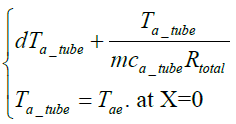
From equations (4) and (5) the flowing equations can be driven;
 (6)
(6)
The air temperature inside the tube at distance X can be calculated as follow;
 (7)
(7)
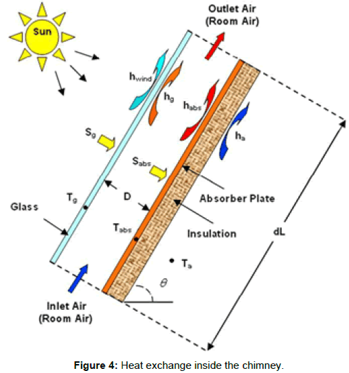
Air flow rate and heat exchange in solar chimney: The heat exchange analogical diagram in an element of solar chimney is shown in Figure 4. The air flow rate through the chimney form bottom inlet to top outlet due buoyancy effect is given by [11].
 (8)
(8)
Where, Cd is the discharge coefficient according to Flourentzou et al. equal 0.60 [11].
The volume of air flow rate  , number of air change per hours
The solar chimney heat balance equations, the heat balance for the glass cover; absorbed solar radiation by glass cover plus radiated heat from absorber equal to convicted heat from cover to chimney air plus conducted heat from cover to outside air:
 (9)
(9)

The heat balance for the absorber; the solar energy transmitted by glass and absorbed by the absorber equal to convicted heat to chimney air plus radiate heat to cover plus conducted heat to room air;
 (10)
(10)
The heat balance for air in chimney; the heat convicted from glass cover plus heat convicted from absorber equal to heat gain in chimney air;
 (11)
(11)
Where, γ mean weighting factor equal to 0.74 by Ong [12].
Tach mean chimney temperature can be calculated from inlet outlet chimney temperature;

Climatic Data of the Ghardaia
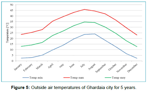
The passive system was used for summer cooling in Ghardaia hot arid region characterized by its high summer temperature, the maximum temperature recorded during July was 47° C. Figure 5 presents the annual recorded maximum, minimum and mean temperature between 2010 and 2014. The mean number of insolated hours per month was 287 h/month, the maximum number of insolated hours was recorded in June 341 h/month Table 1 presents the mean climatic data (temperature, relative humidity, soil surface temperature solar radiation and wind speed) for region where the system supposed to be located.
| Month | Tmean (°C) | RH (%) | Tsurf_sol (°C) | Mean solar R (w/m2) | Mean wind (m/s) |
|---|---|---|---|---|---|
| May | 26,75 | 27,8 | 30,62 | 475,23 | 4,78 |
| June | 31,42 | 25 | 35,26 | 495,69 | 4,34 |
| July | 32,74 | 20 | 40,37 | 488,25 | 3,7 |
| August | 34,24 | 25 | 39,44 | 442,68 | 3,82 |
| September | 30,14 | 34 | 34,51 | 370,14 | 3,58 |
Table 1: Ghardaïa climatic data.
Results and Discussion
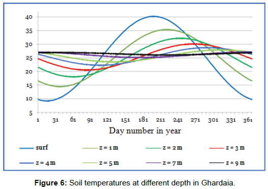
The simulation was done for two rooms, room (A) with cooling passive system, coupled earth to air heat exchange and solar chimney as shown in Figure 1, and reference room (B). The rooms were assumed to be located in Ghardaia. The site soil characteristics are shown in Table 2 and the calculated soil temperature at different depth are shown in Figure 6.
| Density (kg/m3) | Specific heat (J/kg.K) | Thermal conductivity (w.m/K) | Soil reflectivity |
|---|---|---|---|
| 1725 | 1570 | 1.75 | 0.35 |
Table 2: Soil properties.
The passive system is composed as follow; buried parallel PVC tubes with inlet and outlet and solar chimney integrated in well insulated high inertia south wall to protect the room inside space from the chimney heat transfer, the system materials and dimensions are shown in Table 3.
| Elements | Length (m) | Diameter (m) | Section (m2) | Height (m) | Materials |
|---|---|---|---|---|---|
| Outlet | - | 0.3 | - | - | |
| Tubes | 25 | 0.3 | - | - | (PVC) |
| Inlet | - | 0.3 | - | - | |
| SC | 1.00 × 0.15 | - | Glass+Wall | ||
| Inlet SC | - | 1.00 × 0.7 | - |
Table 3: System materials and dimensions.
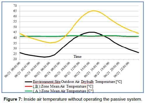
The first simulation was done for room A and B, without any natural ventilation and the passive cooling system in room (A) was chute down, from Figure 7 the inside air temperatures in room (A) varies from 41.98°C to 42.10°C and room (B) varies from 41.27°C to 41.89°C, the temperatures differences between the two rooms was 0.16°C due to heat transfer from chimney to room (A). The two rooms were behaving in same manner, so a comparison between room (A) and (B) when the passive system is working can show the system efficiency.
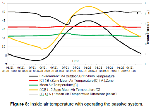
The simulation was done secondly for passive system in room (A) on, from Figure 8, room (A) inside air temperature was lower by 4.9°C than room (B), the lower temperature difference value was occurred between 6 and 11:30 AM due to that the solar chimney inside air temperature was almost equal to the outside air temperature. Room (A) inside air temperatures during night time were higher than the outside air temperatures, night natural ventilation can help in lowering the room inside air temperature [11].
Night natural ventilation effect
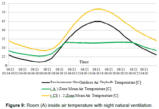
Night natural ventilation was used in room (A), from Figure 9 the inside air temperatures in room (A) varies from 28°C to 33°C so they were lower by 5°C than the non-ventilated one [13].
Effect of tubes disposition in soil
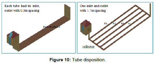
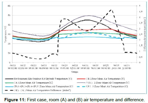
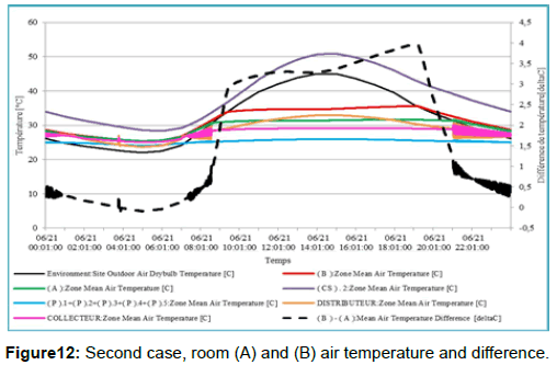
Two ways of tubes dispositions were used in the simulation; firstly each tube had its inlet and outlet with 0.3 m spacing between tubes. Secondly the tubes were connected to one inlet and one outlet with 1.7 m spacing as shown in Figure 10. The inside air temperatures were 31.14°C and 34.56°C in room (A) and (B) respectively for the first case as shown Figure 11. For the second case the inside air temperatures were 31.39°C and 34.56°C in room (A) and (B) respectively as shown Figure 12.
Effect of tube section, number and length
The simulation was done for variable tube diameter (0.30, 0.50, and 0.70 m), variable tube number (6, 8 and 10) and variable tube length (25, 35 and 45 m). Table 4 shows the temperature differences between rooms (A) and (B) for each case. The higher the tube number diameter and length, the higher the temperature difference.
| Diameter m | Length m | 6 tubes ΔT | 8 tubes ΔT | 10 tubes ΔT |
|---|---|---|---|---|
| 0.3 | 25 | 2.1 | 2.22 | 2.3 |
| 35 | 2.13 | 2.25 | 2.33 | |
| 45 | 2.15 | 2.27 | 2.36 | |
| 0.5 | 25 | 3.6 | 3.78 | 3.93 |
| 35 | 3.72 | 3.9 | 4.03 | |
| 45 | 3.79 | 3.97 | 4.09 | |
| 0.7 | 25 | 4.66 | 4.9 | 5.09 |
| 35 | 4.89 | 5.12 | 5.29 | |
| 45 | 5.03 | 5.26 | 5.41 |
Table 4: Room (A) and (B) temperature differences in °C different tubes diameter and length.
Effect of tube collector and outlet section
Table 5 shows the results obtained for 10 buried tubes with 35 m of length and variable diameter (0.30, 0.40, 0.50, 0.60, and 0.70 m), and variable collector and outlet diameter (0.50, 0.75, 1.00 m). The inside air temperature differences between room (A) and (B) were from 2.33°C to 6.41°C. The higher the collector and outlet sections the higher the temperature difference.
| Tube diameter m | The same collector and outlet D | Collector and outlet D 0,50 m | Collector and outlet D 0,75 m | Collector and outlet D 1,00 m |
|---|---|---|---|---|
| 0.3 | 2,33°C | 3,67°C | 4,72°C | 5,33°C |
| 0.4 | 3,21°C | 3,91°C | 5,12°C | 5,84°C |
| 0.5 | 4,04°C | - | 5,36°C | 6,15°C |
| 0.6 | 4,72°C | - | 5,48°C | 6,33°C |
| 0.7 | 5,29°C | - | - | 6,41°C |
Table 5: The inside air temperature differences between rooms (A) and (B) for different collector and outlet diameter.
Effect of tube outlet and chimney inlet positions
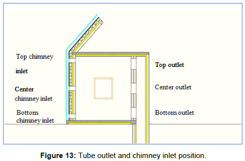
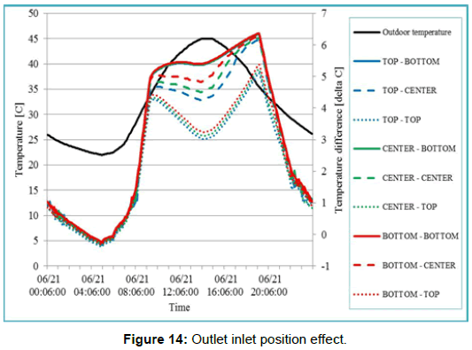
Three positions for tubes outlet inside the room were chosen, top bottom and center, and the same number and positions of inlet from room to the solar chimney as presented in Figure 13. The inside air temperature differences between room (A) and (B) were between 3.01°C and 5.29°C during day time for the following tube outlet and chimney inlet position, top-top, center-top, and bottom-top. The inside air temperature differences between room (A) and (B) were between 4.25°C and 6.27°C during day time for the following tube outlet and chimney inlet position, top-center, center-center, and bottom-center. The inside air temperature differences between room (A) and (B) were between 5.36°C and 6.33°C during day time for the following tube outlet and chimney inlet position, top-bottom, center-bottom, and bottom-bottom. The highest inside air temperature difference was obtained for bottom-bottom tube outlet and chimney inlet positions as shown in Figure 14.
Effect of solar chimney height and inlet section
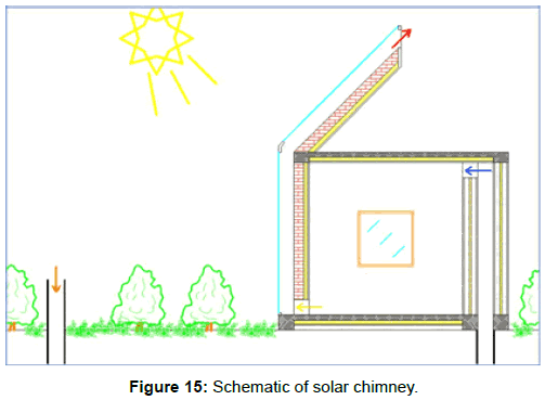
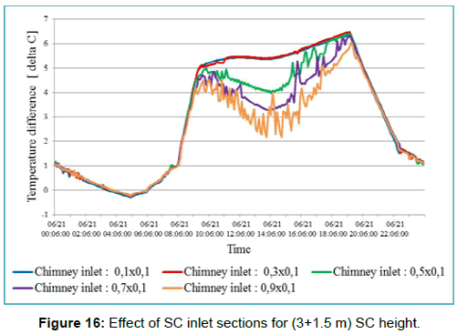
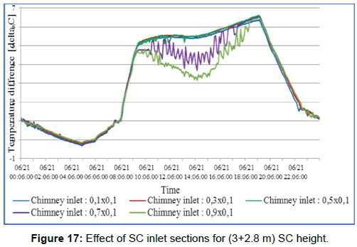
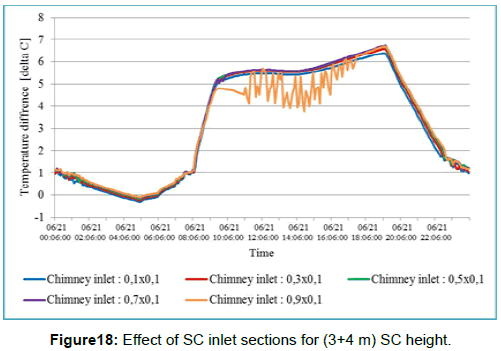
The solar chimney used in the studied passive system was composed of two parts, part one a vertical chimney attached to the south wall and the second suspended attached to roof with an angle of 45° as shown in Figure 15. A variable chimney heights and inlet sections were tested to find the optimum values that give high cooling efficiency. Figures 16-18 show the air temperature difference between rooms (A) and (B) for different chimney height and inlet section. Chimney height of (3 m vertical+1.5 m suspended) with 0.3 × 0.1 m2 inlet section give 6.30°C room (A) and (B) temperature difference when (3 m vertical+4 m suspended) with 0.7 × 0.1 m2 inlet section give 6.70°C. For 2.5 m chimney height difference and 0.4 × 0.1 m2 section difference only small delta temperature of 0.4°C was found, for economic reasons the (3+0.15) m chimney height and 0.3 × 0.1 m2 inlet is recommended.
Effect of chimney number
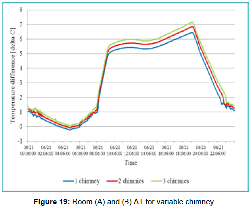
During simulation different chimney configurations were used, one chimney with 0.15 m depth and 1 m wide, two chimneys and three chimneys with the cited same dimensions. From Figure 19 the room (A) and (B) temperatures difference were 6.5°C, 6.8°C and 7.2°C for one, two and three chimneys respectively.
Effect of chimney orientation
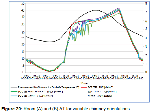
Five chimney orientations were tested from south to west, 180, 202, 225, 247.5 and 270° from north axis, the air flow rates were maximum for each orientation at fixed time as shown in Figure 20. For south orientation the maximum air temperature difference occurred at 14.48 pm, for south orientation the maximum air temperature difference occurred at 15.48 pm and for west orientation the maximum air temperature difference occurred at 16.00 pm. The mean maximum temperature difference was obtained by south chimney orientation.
Conclusion
A numerical simulation was done for a coupled earth to air heat exchange and solar chimney passive cooling system in order to optimize the systems variable parameters and test their effect on the cooling efficiency. The passive system variable parameters are; Pipe: buried depth, cross section, length, disposition, number, and inlet outlet cross sections. Chimney: top and bottom sections, orientation, height, inlet outlet sections and positions, and chimney insulation and inertia. The study show that; a 3 m soil depth with parallel 1.7 m spacing tubes disposition give the lower room (A) inside air temperature of 31.14°C when the outside air temperature was 45°C. Ten buried P.V.C tubes of 0.7 m of diameter and 45 m length give the high cooling efficiency. A center tubes outlet position and 0.7 × 1 m below inlet chimney with a height of 3 m vertical part+1.5 m suspended inclined 45° part of 0.3 × 1 m cross section give the maximum inside room (A) and (B) temperature difference of 6.7°C.
References
- Pérez-Lombard L, Ortiz J, Pout C (2008) A review on buildings energy consumption information. Energy Build 40: 394-398.
- http://www.energy.gov.dz/fr/statistiques/Bilan_Energetique_National_2013_edition_2014. pdf
- Alemu T, Saman W, Belusko M (2012) A model for integrating passive and low energy airflow components into low rise buildings. Energy Build 49: 148-157.
- Benhmmou M (2015) Performance analysis of an earth-to-air heat exchanger assisted by a wind tower for passive cooling of buildings in arid and hot climate. Energy Conversion and Management 91: 1-11.
- Belatrache D (2016) Numerical analysis of earth air heat exchangers at operating conditions in arid climates. International Journal of Hydrogen Energy.
- Khabbaz M (2016) Experimental and numerical study of an earth-to-air heat exchanger. Energy and Building 125: 109-121
- Yuebin Yu (2014) Investigation of a coupled geothermal cooling system with earth tube and solar chimney. Applied Energy 114: 209-217.
- Benhammou M (2011) Draoui Soil temperature modeling for the Adrar region: Affect of soil nature. Renewable Energy Review 4: 219-228.
- Maerefat M, Haghighi AP (2010) Passive cooling by using integrated earth to air heat exchange and solar chimney. Renewable Energy 35: 2316-2324.
- Abdeen Saleem (2016) Solar chimney design for standard ventilation rate of residential buildings in hot-arid climate. 9th International Conference on Indoor Air Quality Ventilation and Energy Conservation in Buildings; IAQVEC.
- Flourentzou F (1998) Natural ventilation for passive cooling, measurement of discharge coefficient. Energy and Building 27: 283-292.
- Ong KS (2003) A mathematical model of a solar chimney. Renewable Energy 28: 1047-1060
- Bencheikh H (2015) The effect of night natural ventilation and wind speed. Renewable Energy in the Service of Mankind 1: 423-432.
Citation: Bencheikh H, Daoudji Y (2018) Numerical Investigation of a Coupled Passive Cooling System Earth to Air Heat Exchange and Solar Chimney in Hot Arid Zone. Innov Ener Res 7: 188. DOI: 10.4172/2576-1463.1000188
Copyright: © 2018 Bencheikh H, et al. This is an open-access article distributed under the terms of the Creative Commons Attribution License, which permits unrestricted use, distribution, and reproduction in any medium, provided the original author and source are credited.
Select your language of interest to view the total content in your interested language
Share This Article
Recommended Journals
Open Access Journals
Article Tools
Article Usage
- Total views: 5735
- [From(publication date): 0-2018 - Nov 22, 2025]
- Breakdown by view type
- HTML page views: 4781
- PDF downloads: 954

