Special Issue Article Open Access
Novel At-Face-Slurry Performance Modeling with Elliptical and Spherical Geometries
Raymond S. Suglo1*, Samuel Frimpong2 and Osei F. Brown3
1Department of Mining and Nuclear Engineering, Missouri S&T, Rolla, University of Missouri, USA
2Department of Mining and Nuclear Engineering, Missouri S&T, Rolla, MO 65409, Room 226 McNutt Hall, 1870 Miner Circle, USA
3Missouri S&T & Mining Engineer, Freeport McMoran Inc, USA
- *Corresponding Author:
- Raymond S. Suglo
Associate Professor of Mining Engineering
Department of Mining and Nuclear Engineering
Missouri S&T, Rolla
University of Missouri, USA
E-mail: rsuglo@yahoo.ca
Received Date: January 15, 2013; Accepted Date: January 17, 2013; Published Date: January 26, 2013
Citation: Suglo RS, Frimpong S, Brown OF (2013) Novel At-Face-Slurry Performance Modeling with Elliptical and Spherical Geometries. J Powder Metall Min S1:006. doi: 10.4172/2168-9806.S1-006
Copyright: © 2013 Suglo RS, et al. This is an open-access article distributed under the terms of the Creative Commons Attribution License, which permits unrestricted use, distribution, and reproduction in any medium, provided the original author and source are credited.
Visit for more related articles at Journal of Powder Metallurgy & Mining
Abstract
Surface mine production scheduling and sequencing are used to maximize the expected profit and investment returns from mining operations. The pit geometries and expansion rates, and the periodic volume of materials from different benches in a multi-bench, multi-face open pit mine determine the equipment requirements, which impact the maximize just-in-time (JIT) production decisions. The analytical geometric volume calculations require time lags that prevent rapid information for JIT decisions. The introduction of the novel At-Face-Slurry (AFS) oil sands method require fast, accurate and repeatable pit volume estimation using continuous flow process. The first part of this paper shows how partial differential equations (PDEs) and geometric techniques were used in modeling material volume, as well as pit layout changes with circular and elliptical geometries of an oil sands mine. The second part contains the economic analysis on the current mining system (CMS) and the cyclic excavator conveyor belt control system (CycEx CBCS).
A continuous flow process via PDEs was used to model material volume, as well as pit layout changes with
circular and elliptical geometries of an oil sands mine and compared with analytical geometric methods. PDEs were used in the modeling due to the continuous nature of the changes in the volumes of the pits with time. The geometric and PDEs values are similar for the pit configurations. This work represents the first successful attempt at using PDE in geometric calculations for open pit mines. The economic analysis shows that the NPV of the current mining system (CMS) is $3.2×10¹⁰ while that for the cyclic excavator conveyor belt control system (CycEx CBCS) is $4.06×10¹⁰. The Profitability Index (PI) for the CMS and CycEx CBCS options are 19.37 and 43.37 respectively. The IRR of the CMS option is 29.02% while that of the CycEx CBCS option is 33.37%. The DPBP for the CMS and CycEx CBCS options are 3.24 months and 1.92 months, respectively. The CMS option has an operating cost of $1.386/tonne ($2.774/barrel) while that of the CycEx CBCS option is $0.779/tonne ($1.558/barrel). The requirement for a fast, accurate and repeatable process for generating pit volumes is met by using PDEs.
Introduction
Surface mine production scheduling and sequencing can be challenging due to the fact that most open pit mines work with multiple benches and often involve the simultaneous excavation of both ore and waste from a number of working faces [1-4]. These production schedules and plans are used to maintain and maximize the expected profit [5]; to determine the future investment in mining; to optimize return on investment; to evaluate alternative investment options; and to conserve and develop the pit resources [6]. The pit geometries and expansion rates, and the periodic volume of materials from different benches in a multi-bench, multi-face open pit mine determine the equipment requirements, which impact the maximized pit value. Under such regimes, fast, accurate, and repeatable estimation of pit volumes are required for just-in-time (JIT) production decisions [7]. The analytical geometric volume calculations require time lags that prevent rapid information for JIT decisions. The introduction of the novel AFS oil sands method provide fast, accurate and repeatable pit volume estimation using continuous flow process.
Most open pit cross-sections are either circular or elliptical. Geometric calculations and PDEs were employed to accurately determine the volumes of materials excavated in these pits. The pit dimensions are expanded and deepened by lateral and longitudinal incremental pushbacks. Materials handling is mainly by discrete or continuous flow units and processes. Discrete materials loading and haulage systems are predominantly used in open pit mines because they allow high flexibility in planning and scheduling of operations and easily cope with the frequent changes in the pit configuration. As open pit layouts expand, equipment cycle times and haulage costs increase, resulting in lower production rates and system efficiencies. Thus, there is a need for cheaper mining and haulage systems for ensuring optimum profitability. Bulk materials transport systems, such as belt conveyors and hydraulic transport systems offer lower operating costs. They are also versatile with practically unlimited range of capacities and are increasingly being employed in the bulk transportation of materials in large surface mines. They offer competitive economic advantages over cyclic materials handling systems.
The novel AFS system will take advantage of the lower unit operating costs, higher payload-dead weight ratio, and higher efficiencies of continuous transport systems by extending the transport systems to production faces. The face shovel in the AFS system will be linked to the treatment plant by mobile trains using either hoppercrusher- belt conveyor wagons-slurry facility or hopper-crusher-slurry facility-flexible/fixed pipeline system. Thus, the excavation, crushing and slurry process will be done at the face before being pumped to the treatment plant. The AFS system will introduce a unique set of mine design layout, configuration, and ergonomic challenges by allowing the mobile train of flexible pipelines or conveyor belt systems to adapt to the production face dynamics.
The shovel-truck system, referred to as the current mining system (CMS), is widely used in most surface mines. CMS comprises shovels as the primary loaders with diesel-powered dump trucks that are dispatched or allocated to each excavator. The loaded trucks transport the materials to dump sites at the crusher-slurry facility or to the waste dump site. The system comprises discrete loading and haulage units whose outputs are characterized by their cycle times. Due to its flexibility, mobility, and resale value, truck haulage is the favored method for moving both ore and waste in open pit mines [8].
The CycEx CBCS comprises a shovel, a crawler-mounted mobile crusher, belt conveyor wagons, a mixing tower and a slurry facility. The shovel loads its materials into a crawler-mounted hopper located at the face. Apron feeders transfer the materials to sizers then into double roll crushers for size reduction. The crushed materials will be sized and conveyed on a train of crawler-mounted belt conveyor wagons to a surge facility from which apron feeders will transport it to a slurry facility. The oil sands slurry is transported through the main hydrotransport system (HTS) to the main processing plant [9,10]. The slurry unit is also fed from multi-bench, multi-face mining and materials flow system. This ensures continuous flow of materials from the cyclical shovels to the slurry unit. The aim is to meet the required production targets, and avoid downtimes of the slurry unit because of a problem at any of the mining faces.
Different combinations of equipment can be used in a mine to achieve the desired production targets. However, some equipment combinations and their operating times result in lower unit operating costs and higher system efficiencies than others. The main objectives of this study include:
i) Development of mathematical models governing the evolution of the surface mine layouts associated with the current mining system and the novel AFS methods.
ii) Geometric calculations of material flow from an oil sands mine with circular and elliptical pit shapes.
iii) Comparative analysis of production-economic functions of the CMS and CycEx CBCS options.
The next paragraph contains the mathematical models that capture the evolution of the pit layout configuration. PDEs were used in the modeling due to the continuous nature of the changes in the volumes of the pits with time. Geometric estimation of pit layouts and a comparative economic analysis of the CMS and CycEx CBCS options are presented in the following paragraphs.
Dynamic geometric models
The dynamic evolution of AFS layouts and material flow from multi-bench, multi-face pit configurations are presented for the CMS and CycEx CBCS options. Solid geometry and PDEs are used to model and analyze the continuous flow of materials by volume. The volume of materials generated by incremental changes in the pit dimensions are calculated by a combination of the frustum methods and parabolic partial differential equations [7,11]
Dynamics of circular pit geometry material volume
The volume of a frustum (Figure 1), assuming a right circular conical cross-section, with radii a0 and a1 at the top and bottom respectively and a bench height, H, is given by equation 1 [12,7].
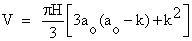 (1)
(1)

Figure 1: Frustum on First Bench with Radii a0 and a1.
where k=H/tanθ
But a1=a0–H/tanθ=a0–k. Thus the volume of materials excavated from the circular frustum in figure 1 may be expressed as in equation 2.
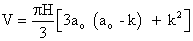 (2)
(2)
Assuming that mining on subsequent benches begins when pit radius on previous bench has advanced by a minimum distance of B+H/tanθ, then the change in volume of the frustum between the ith and jth incremental pushback, mined on the nth bench is given by equation 3 [13].
 (3)
(3)
Dynamics of elliptical pit geometry material volume
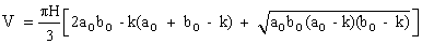
Figure 2 shows a pit with an elliptical cross-section. If an incremental pushback is taken, then the change in volume of the ellipsoid can be obtained using solid geometry. If the dimensions of the major and minor axes at the top of frustum in Figure 2 are 2a0 and 2b0 respectively, while those of the ellipse at a depth of one bench height, H, are 2a1 and 2b1 respectively, then the volume of the elliptical frustum is given by equation 4.
 (4)
(4)

Figure 2: Elliptical Pit Section with one Incremental Pushback, Δx.
Thus, equation 5 expresses the volume of materials excavated from the elliptical frustum in terms of a0 and b0.
 (5)
(5)
If an incremental pushback, Δx, is taken along both the major and minor axes, then the radii of the top and bottom ellipses increase by the same amount. The new volume of the frustum is given by equation 6.
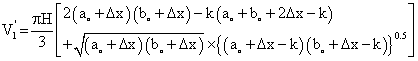 (6)
(6)
For n incremental pushbacks, the new volume of an elliptical pit is given by equation 7.
 (7)
(7)
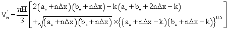
Equation 8 gives the change in volume of the elliptical frustum, ΔV, from one incremental pushback to the next.
 (8)
(8)
Continuous-time bench material flow model
In general, the shape of the pit changes with time as mining is carried out on various benches. To find the rate of change in the volume of the pit when the incremental pushbacks are taken in only one direction, it is necessary to employ continuous time formulation to model the changes in pit volume. Using the chain rule, the rate of change in the volume of the pit with circular and elliptical cross-sections in any direction with time are determined by partial differentiation of the volume with respect to the dimensions of the pit (i.e. a0, b0, H and k).
Circular pit geometry
Applying the chain rule to the volume of a circular frustum, in equation 2, results in equation 9.
 (9)
(9)
Since H, θ and the geotechnical parameters of the rock do not change with time, ∂H/∂t=0, ∂θ/∂t=0 and ∂k/∂t=0, thus equation 9 simplifies to equation 10
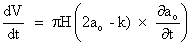 (10)
(10)
Equation 10 shows that the rate of change in volume of a circularshaped pit is directly proportional to the rate of change of the radius of the pit with time.
Elliptical pit geometry
A similar analysis for an elliptical frustum of volume given by equation 5 gives the rate of change of the volume of an elliptical pit as equation 11:
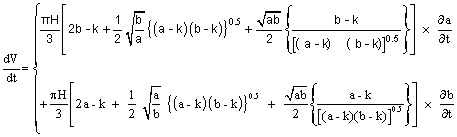 (11)
(11)
Thus, given the values of a0, b0, H, k and θ, the rate of change in volume of either the circular frustum or the elliptical frustum with time can be calculated using equations 10 and 11 respectively.
Multi-Face, Multi-Bench Material Flow Dynamics
The daily production target is 262,000 tonnes at a stripping ratio of 1.1:1 (on a ton-ton basis). Thus, for every tonne of ore mined, 1.1 tonnes of waste are removed from the pit. The thickness of the deposit averages 60 m. The height and slope of a bench are 13 m and 50°, respectively. The geometric and parabolic PDEs equations were modeled in Matlab and executed to determine the pit volumes and expansion rates with elliptical and spherical geometries for evaluating the performance of CSM and CycEx CBCS in the different pit configurations.
Figure 3 is a 3D pit layout with three benches. Figure 4 is a solid 3D layout of the faces of a circular pit after taking 10 incremental pushbacks of 10 m each. The initial pit radius in Figure 4 is 80 m while the final pit diameter at the top is 381.82 m after taking 10 pushbacks on bench 1. The spaces in between the colored circular frustums show the voids created after each pushback. The pit limits are reached when the radius of the pit reaches the shortest length of the property boundaries. In this case the calculations are terminated when the radius of the pit is 3,000 m.

Figure 3: 3D View of a Circular Pit with 3 Benches.

Figure 4: 3D Circular Pit Faces after taking Incremental Pushbacks on Bench #1.
Figure 5 is a 3D view of an elliptical pit after 10 incremental pushbacks each of 10 m in thickness. The initial pit dimensions are 328 m×208 m while the final pit diameter at the top is 549.82 m×431.82 m on bench 1. The pit limits are reached when the pit dimensions along the minor axis reach the boundary conditions. In this case the calculations are terminated when the initial length of the minor axes of the elliptical cross-section is 3,000 m.

Figure 5: 3D View of Elliptical Pit Faces after Incremental Pushbacks.
Table 1 summarizes the volume of ore excavated and times to completely mine all the ore in a circular pit using CMS and CycEx CBCS options on benches 1 to 3.
| Bench | Mining Option | Volumes (m3 × 108) | Time to Mine | |
|---|---|---|---|---|
| Days | Years | |||
| Bench #1 | CMS | 3.66 | 2,932.48 | 8.03 |
| CBCS | 3.65 | 2,924.53 | 8.01 | |
| Bench #2 | CMS | 3.44 | 2,758.25 | 7.56 |
| CBCS | 3.23 | 2,592.07 | 7.10 | |
| Bench #3 | CMS | 3.23 | 2,585.81 | 7.08 |
| CBCS | 2.84 | 2,279.59 | 6.25 | |
Table 1: Volume of materials excavated from Circular Pit.
The results show that when the CMS option is used, the oil sands reserves on bench #1 would be mined out in 8.03 years at the projected production rate of 262,000 t/d. Detailed geometric calculations show that it will take between 0.11 to 3.76 days to mine the ore materials within each incremental pushback in all directions on bench #1. The ore on benches 2 and 3 will be completely mined out in 7.56 years and 7.08 years respectively. Ore extraction from benches 2 and 3 are delayed until enough space is available on the previous bench. Mining on bench 2 starts about 174 days after starting bench 1. As well, mining on bench 3 begins 172 days after mining has started on bench 2.
Using the CycEx CBCS option, within a circular pit configuration, geometric estimates show that the ore on benches 1 to 3 will be completely mined out within 6.25 and 8.01 years. Mining on bench 2 starts about 332 days after bench 1. As well, mining on bench 3 begins 313 days after mining has started on bench 2.
Table 2 summarizes the results of the volumes excavated from benches 1 to 3 and the times taken to mine all the ore in an elliptical pit. The results show that it will take between 7.21 years and 8.17 years to mine the materials from benches 1 to 3 using the CMS option. On the other hand, it will take from 6.39 to 8.19 years to completely mine all the ore on benches 1 to 3 using the CycEx CBCS method. The remaining reserves along the major axis on these benches can then be mined later and the volumes calculated using PDEs.
| Bench | Mining Option | Volumes (m3 × 108) | Time to Mine | |
|---|---|---|---|---|
| Days | Years | |||
| Bench #1 | CMS | 3.72 | 2,982.73 | 8.17 |
| CBCS | 3.73 | 2,989.51 | 8.19 | |
| Bench #2 | CMS | 3.50 | 2,807.02 | 7.69 |
| CBCS | 3.31 | 2,653.45 | 7.27 | |
| Bench #3 | CMS | 3.29 | 2,633.08 | 7.21 |
| CBCS | 2.91 | 2,334.02 | 6.39 | |
Table 2: Volume of materials excavated from Elliptical Pit
Figure 6 shows the respective rates of change of volume of the circular pit at any given time using PDEs when the CMS and CycEx CBCS options are used respectively. The volumes of ore that can be mined from benches 1 to 3 of the circular pit using the CMS and CycEx CBCS options are given in table 1. From figure 6, if the differential volume expansion of the pit is known, then the excavation time can be obtained from the x-axis or vice versa. It is determined from the figure that the reserves on benches 1, 2 and 3 will be excavated after about 69,600 hours (2,908.33 days), 67,500 hours (2,812.50 days) and 65,000 hours (2,708.33 days) respectively. The calculations also show that the rate of increase in the pit dimensions was about 0.048 m/hr. Figure 7 shows the initial AFS equipment layout in a circular pit for the application of the CycEx CBCS option.

Figure 6: Volume of Circular Pit vs. Time using CMS and CycEx CBCS.

Figure 7: Initial AFS Equipment Layout in a Circular Pit (Suglo, 2004).
Figure 8 shows the respective rates of change of the volume of an elliptical pit at any given time when the CMS and CycEx CBCS options are used respectively. It shows that the rate of change in the volume of the elliptical pit is virtually the same irrespective of the type of mining option. The geometric volumes of ore that can be extracted from the elliptical frustum on benches 1 to 3 using the CMS and CycEx options are given in table 2. From figure 8, the ore contained on benches 1, 2 and 3 will be extracted in 69,600 hours (2,900 days), 68,200 hours (2,841.67 days) and 65,100 hours (2,710 days) respectively. The dimensions of the elliptical frustum on bench #1 will expand at the rate of 0.046 m/hr. Figure 9 shows the initial AFS equipment layout in an elliptical pit for the application of the CycEx CBCS option.
Figure 8: Elliptical Pit vs. Time using PDEs on Bench #1 for CMS and CycEx CBCS Option.

Figure 9: Initial AFS Equipment Layout in an Elliptical Pit (Suglo, 2004).
Tables 3 and 4 summarize the required periods for mining all the ore on benches 1 to 3 using geometric calculations and PDEs for circular and elliptical pit configurations respectively. The results show that the values from MATLAB geometric calculations are almost the same as those obtained from PDEs for the different pit configurations. Thus, PDEs may be successfully used in volume calculations to arrive at the same values as obtained from geometric process. However, calculations using PDEs for pit expansion in all directions are usually terminated when the boundary conditions along the minor axis or shorter dimensions of the property boundaries are attained. The results show that the PDE calculations tend to overestimate the volumes excavated as the pit deepens (i.e. at the lower benches) relative to geometric calculations. This may leave some reserves in the pit along the major axis whose volume can be similarly determined using PDEs if excavation is assumed to be taking place in only that direction.
| Geometric (days) | PDE (days) | Ratio | ||
|---|---|---|---|---|
| Bench #1 | CMS | 2,934.25 | 2,908.33 | 1.01 |
| CBCS | 2,926.90 | 2,854.17 | 1.03 | |
| Bench #2 | CMS | 2,778.26 | 2,812.50 | 0.99 |
| CBCS | 2,615.68 | 2,600.00 | 1.01 | |
| Bench #3 | CMS | 2,630.10 | 2,708.33 | 0.97 |
| CBCS | 2,635.24 | 2,541.67 | 1.04 | |
| Average | 1.01 | |||
Table 3: Excavation Periods for Circular Pit Reserves.
| Geometric (days) | PDE (days) | Ratio | ||
|---|---|---|---|---|
| Bench #1 | CMS | 2,984.33 | 2,900.00 | 1.03 |
| CBCS | 2,987.87 | 2,991.67 | 1.00 | |
| Bench #2 | CMS | 2,827.03 | 2,841.67 | 0.99 |
| CBCS | 2,673.50 | 2,780.50 | 0.96 | |
| Bench #3 | CMS | 2,677.58 | 2,710.00 | 0.99 |
| CBCS | 2,376.56 | 2,497.53 | 0.95 | |
| Average | 0.99 | |||
Table 4: Excavation Periods for Elliptical Pit Reserves.
Economic Analysis of Pit Mining Options
The CMS and CycEx CBCS options have been economically evaluated to assess their value and viability due to the associated high capital investments and risks. Even though the cost of production per tonne from the two options may be used to determine the better option, it is much better to assess both options using the appropriate evaluation economic criteria. It is also often necessary to assess the effect of changes in the discount rate because with most new operations, investors often apply high discount rates at the start of operations. Over the years as more information is gathered and various parameters are known to high levels of certainty, the discount rates may be reduced to reflect the level of confidence in the project parameters. In addition, it is also necessary to assess the impact of federal and state taxes on the viability of projects at various tax levels. Due to the unpredictable nature of mineral prices and other economic factors, as well as the frequent changes in political regimes in some states and provinces, project parameters have to be subjected to rigorous viability and risk analyses to make risk-based decisions. Thus, comprehensive economic and risk analyses are required for all the possible scenarios to ensure proper comparison of the various mining options.
In this study, one barrel of oil is obtained for every two tonnes of ore. The collected data are processed using the stabilized probability plot method and Best Fit [14]. The results show that the data closely fit various statistical distributions [13,14]. The costs were assumed to vary by ± 25% of their mean values. The Double Declining Balance (DDB) method of depreciation is used at the mine. The depletion allowance is taken as the minimum of 5% of gross revenue and 10% of Pre-Capital Cost Allowance (PreCCA) while the average exchange rate of the US $ to the Canadian $ for the past 7 years was 1.03. Contingency allowance is equivalent to 25% of the cost. A detailed economic analysis on the CMS and CycEx CBCS options is carried out [15-19].
Table 5 summarizes the results of the economic analysis conducted on the two mining options. The results show that both mining options are viable with high NPV (≥ $3.20×10¹⁰), PI (>19%) and IRR (>29.02%) and extremely short discounted PBP (≤ 3.24 months). From table 5, the CycEx CBCS option is clearly more economic than the CMS option. Its NPV is 1.27 times that of the CMS option. The PI and IRR of the CycEx CBCS option are respectively 2.24 and 1.13 times that of the CMS option. As well, the CycEx CBCS option has almost half the DPBP of the CMS option. Using a discount rate of 15%, the CycEx CBCS option is clearly the better option.
| Profitability Measure | Mining Option | Ratio (CBCS/CMS) | |
|---|---|---|---|
| CMS | CycEx CBCS | ||
| NPV ($1010) | 3.20 | 4.06 | 1.27 |
| PI | 19.37 | 43.37 | 2.24 |
| IRR () | 29.02 | 33.37 | 1.15 |
| DPBP (yr) | 0.27 | 0.16 | 0.59 |
Table 5: Economic Analysis of Mining Options.
Table 6 summarizes the total operating costs of the CMS and CycEx CBCS options. The results show that the CMS option has an operating cost of $1.39/tonne ($2.78/barrel) while that of the CycEx CBCS option is $0.78/tonne ($1.56/barrel). Thus the unit operating cost of the CMS option is about 1.78 times that of the CycEx CBCS option. This means that it is cheaper for oil sands mining companies to adapt the CycEx CBCS option as against the CMS to increase project profitability.
| Type of Equipment | No. of Units | Maintenance Cost ($ x 106) | Operator Cost ($/min) | Total No. Operators | Total Operator Cost ($ x 106) | Total Cost ($ x 106) |
| CMS Option | ||||||
| Trucks (360 t unit) | 24 | 14.40 | 1.60 | 36 | 30.27 | 55.84 |
| Shovel (O&K RH200) | 6 | 22.80 | 2.20 | 18 | 20.81 | 54.52 |
| Crusher | 1 | 7.66 | 1.60 | 12 | 10.09 | 22.18 |
| Total Operating Cost ($ x 106) | 13.25 ± 2.26 | |||||
| Operating Cost per tonne ($/tonne) | 1.386 ± 0.07 | |||||
| CycEx CBCS Option | ||||||
| Type of Equipment | No. of Units | Maintenance Cost ($ x 106) | Operator Cost ($/min) | Total No. Operators | Total Operator Cost ($ x 106) | Total Cost ($ x 106) |
| Belt conveyor wagons (20 m) | 18 | 6.75 | 1.6 | 9 | 7.57 | 17.90 |
| Mobile transfer conveyor | 2 | 2.94 | 1.6 | 6 | 5.05 | 9.98 |
| Hydrotransport Pipelines | 1 | 0.15 | 1.6 | 6 | 5.05 | 6.49 |
| Shovel (O&K RH200) | 6 | 3.80 | 2.2 | 12 | 13.87 | 22.09 |
| Mobile Crusher & Slurrification unit | 1 | 1.80 | 1.6 | 15 | 12.61 | 18.02 |
| Total Operating Costs ($ x 106) | 74.49 ± 4.66 | |||||
| Operating Cost per tonne ($/tonne) | 0.779 ± 0.023 | |||||
Table 6: Summary of Operating Costs of CMS and CycEx CBCS Options.
Conclusions
Mathematical models have been formulated to capture the evolution of the surface mine layouts. Geometric calculations and PDEs have been used to determine the pit volumes and expansion rates of pits with elliptical and spherical geometries. PDEs were used in the modeling due to the continuous nature of the changes in the volumes of the pits with time. The excavation periods for the ore contained in benches 1 to 3 using the CMS and CycEx CBCS options were also computed. The results show that the calculated values from geometric calculations using Matlab are almost the same as those obtained from PDEs for different pit configurations. Thus PDEs may be successfully used in volume calculations to yield the same values as geometric estimates. However, calculations using PDEs for pit expansion in all directions are usually terminated when the boundary conditions along the minor axis or shorter dimensions of the property boundaries are attained. The results of the economic analysis show that both the current mining system which involves shovels and trucks and the conceptual AFS option, the cyclic excavator conveyor belt control system (CycEx CBCS), are viable with higher NPV values (≥ $3.20×10¹⁰), PI (>19%) and IRR (>29.02%) and extremely short DPBP (≤ 3.24 months). Thus, the CycEx CBCS option is more economically viable than the CMS option. Its NPV is 1.27 times that of the CMS option. The PI and IRR of the CycEx CBCS option are respectively 2.24 and 1.13 times that of the CMS option. As well, the CycEx CBCS option has almost half the DPBP of the CMS option. The CMS option has an operating cost of $1.386/ tonne ($2.774/barrel) while that of the CycEx CBCS option is $0.779/ tonne ($1.558/barrel). Thus the unit operating cost of the CMS option is about 1.78 times that of the CycEx CBCS option. These results show that the CycEx CBCS option is clearly the better option for mining companies working on oil sands deposits to invest in.
References
- Dohm GC (1979) Circular Analysis–Open Pit Optimization, in. Ch. 21 of Open Pit Mine Planning and Design. American Institute of Mining, Metallurgical, and Petroleum Engineers, New York, USA.
- Bohnet EL (1989) Optimum Production Scheduling, in Ch. 5.4 of Surface Mining (B.A. Kennedy, ed.), 2nd ed., AIME, Baltimore: 476-479.
- Armstrong D (1990) Planning and Design of Surface Mines, in Ch. 5 of Surface Mining (B.A. Kennedy, ed.), 2nd ed., AIME, Baltimore: 459-464.
- Erarslan K (2002) A Practical Approach for Open Pit Design and Visualisation. Journal of Mineral Resources Eng 9: 313-321.
- Hustrulid W, Kuchta M (1995) Open Pit Mine Design and Planning, Fundamentals. A.A. Balkema, Rotterdam 1: 1-625.
- O’Neil T (1998) Syncrude: Biggest Oil-Sand Miner gets Biggest Hydraulic Shovel. Mining Engineering.
- Frimpong S, Asa E, Suglo RS (2001) Numerical Simulation of Surface Mine Production System using Pit Shell Simulator. J Min Res Eng2: 185-203.
- Frizzell EM, Martin TW (1992) In-Pit Crushing and Conveying, in Ch. 13.5 of SME Mining Engineering Handbook, AIME, Baltimore.
- Changirwa R, Frimpong S, Szymanski J (2000) AFS Recommended Option”, Collaborative Research on an At Face Slurrying (AFS) Technology–NSERC-Syncrude-University of Alberta, Progress Report 1-61.
- Coward J (2000) Communication with Syncrude Canada Ltd.
- Suglo RS (2004) Geometrical Mine Design and Multi-Bench Material Flow Simulation for AFS Characterization. University of Alberta, Edmonton, Canada.
- Etgen GA (1995) Salas and Hille’s Calculus (7th edition) J. Wiley & Sons.
- Suglo RS, Szymanski J (1995) Computer Simulation of Underground Room and Pillar Mining. Proceedings of Underground Operators’ Conference, Kalgoolie, November 13: 1-4.
- Anon (1997) RISK: Risk Simulation and Analysis for Spreadsheets. Palisade Corporation, Newfield, USA.
- Anon (2001) Why We’re Here Syncrude Canada Ltd.
- Anon (2001) Project Millennium–Suncor Ramping Up to Double Production CIM Bulletin 1054: 13-27.
- Anon (2003) The Current Economy–Analysis of the Current State of the Economy Government of Canada.
- Anon (2003) Bank of Canada–Monetary Policy, Bank of Canada.
- Coward J (2003) Communication with Syncrude Canada.
Relevant Topics
- Additive Manufacturing
- Coal Mining
- Colloid Chemistry
- Composite Materials Fabrication
- Compressive Strength
- Extractive Metallurgy
- Fracture Toughness
- Geological Materials
- Hydrometallurgy
- Industrial Engineering
- Materials Chemistry
- Materials Processing and Manufacturing
- Metal Casting Technology
- Metallic Materials
- Metallurgical Engineering
- Metallurgy
- Mineral Processing
- Nanomaterial
- Resource Extraction
- Rock Mechanics
- Surface Mining
Recommended Journals
Article Tools
Article Usage
- Total views: 16411
- [From(publication date):
specialissue-2013 - Jul 05, 2025] - Breakdown by view type
- HTML page views : 11729
- PDF downloads : 4682