More Electric Aircraft for Greener Aviation (A Comparative Study)
Received: 25-Jul-2022 / Manuscript No. EPCC-22-70202 / Editor assigned: 27-Jul-2022 / PreQC No. EPCC-22-70202 (PQ) / Reviewed: 10-Aug-2022 / QC No. EPCC-22-70202 / Revised: 13-Aug-2022 / Manuscript No. EPCC-22-70202 (R) / Published Date: 20-Aug-2022 DOI: 10.4172/2573-458X.1000292
Abstract
Climate change is a grave concern, and contribution of the airline industry due to air pollution, noise pollution and heavy consumption of fossil fuel cannot be ignored. For a sustainable future, the airline industry needs to shift towards cleaner, more efficient aircraft. In order to reduce dependency on conventional sources of energy such as oil,electrical energy utilization, such as in Electric Vehicle, is being motivated today. One such step towards building a more environment-friendly aircraft is More Electric Air-craft (MEA), which replaces traditional hydraulic and pneumatic systems by an electrical system with help of power electronic devices so that air-crafts can reduce fuel consumption and generate more thrust while carrying the same or more, number of passengers/amount of freight. This paper discusses the working system of More Electric Air-craft and a comparative study with conventional aircraft system and how MEA can play a substantial role in conserving the environment and reduce the emission of greenhouse gases and heat by increasing fuel efficiency. Potential possibilities for future and trends are also discussed.
Keywords
Climate change; Electric Vehicle; Greener Aviation
Introduction
By 2030, emissions have to be 55 per cent lower than in 2018 to limit global warming to below 1.5ºC [1]. Aviation accounts for 3% of greenhouse gases being emitted in Europe and has increased by 87% per cent since 1990 [2]. Germany’s emissions in 2018 were 867.7 Million Metric Tonnes (MMT) [3], whereas commercial jets in 2018 emitted 918 MMT of CO2, forming 2.4% of CO2 emitted through fossil fuels globally and, has increased by 32% since 2014[4].
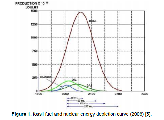
If we observe Figure 1 the oil curve is peaking at the current point of time and is seen to be dwindling towards exhaustion afterwards. Saving fossil fuels, by using high-efficiency machines and transport vehicles is becoming necessary. The weight of the air-craft and extraction of bleed air from engines for secondary power are some of the hurdles in the way of air-crafts becoming more efficient. If we save one kilogram of weight on every flight, we could end up saving 5400 tons of CO2 emission and 1700 tons of fuel, annually [5,6]. The goal of MEA is to make air-crafts more environments friendly by replacing a traditional air-craft system which consists of hydraulic, mechanical and pneumatic power sources by an electrical system. The combined electrical horsepower capacity of MEA is expected to be 25% less than conventional hydraulic, pneumatic and electrical system [7]. Secondary systems which are employed currently were developed at a time when fuel was cheaper therefore maximum efficiency capability, of the secondary system, has not been fully explored [8]. The electrical system is greener, easy to control, reduces the weight of aircraft, reduces the number of mechanical parts and increases the efficiency of the engine. Which ultimately results in lower- emissions, maintenance cost, ground time and higher reliability (Figure 1).
According to a NASA study a 200 seater more electric aircraft could contribute towards a 10% reduction in aircraft empty weight, a 13% reduction in required engine thrust and a 9% reduction in aircraft fuel burn [9]. The goal of this paper is to present an overview of the possible technological changes in, conventional aircraft, system so as to make it environmentally responsible and contribute towards curbing climate change.
Comparative study of the electrical system in mea and conventional air-crafts
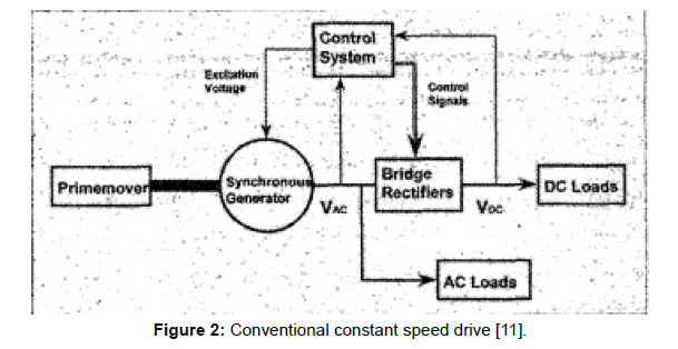
Electrical loads on a commercial air-craft include entertainment units, fans, cabin lighting, kitchen loads, speakers, backup generators etc. Conventional aircraft system typically uses constant speed drive, shown in Figure 2, to generate 115V/400Hz AC. 115VAC is converted to 28VDC or 14VDC which is used to operate avionics equipment (at levels of 5V, 3V, 12V etc.). Although DC can be extracted directly from the engines by using a DC generator but due to low availability of space near the engines it is complicated to install another generator, also DC conductors that would be used to connect the generator to DC bus are bulky and will add to the weight of aircraft, therefore in constant frequency architecture, AC is converted to DC (by using Transformer Rectifier Unit (TRU)) [10] (Figure 2).
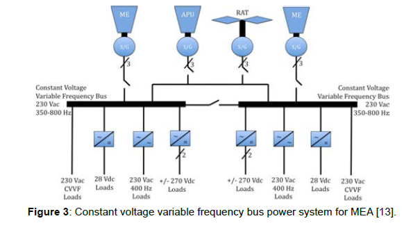
Whereas in modern more electric air-crafts, such as B787, constant voltage and constant frequency system is replaced by constant voltage (115VAC or 230VAC) and variable frequency (350Hz-800Hz) system [11,12], as shown in Figure 3. Table 1 compares the electrical characteristics of some modern air-crafts. In MEA a higher voltage level means a reduction in weight of the conductors (however optimum voltage level is not the maximum level of voltage that could be produced [12], a methodology to calculate optimum and safe voltage level is presented in reference [12]), In MEA electrical architecture, power before being distributed to various loads, is processed by electronic systems because a variable frequency is generated, which depends on the speed of the engine. The first variable frequency system was used in Airbus A380 model, it has advantages such as the ability to produce only as much power as needed, which reduces fuel consumption and it simplifies constant speed mechanical gearbox [13], thus subtracting weight from the aircraft (Figure 3).
| AIRCRAFT | BOEING | AIRBUS | AIR BUS |
|---|---|---|---|
| 787 | 380 | 350 | |
| Number Of Engines | 2 | 4 | 2 |
| Number Of Generators per engine | 2 | 1 | 2 |
| Generator rating per engine | 250kVA | 150kVA | 100k VA |
| Generator output voltage | 235V | 115V | 230V |
| Number of generatorsper APU | 2 | 1 | 1 |
| Generator rating per APU | 225kVA | 120kVA | 150k VA |
| RAT rating | 150kVA | 100k |
Table 1: comparison of the key electrical systems of recent large commercial transport aircraft [13].
In More electric system 230 VAC is converted to +270VDC or -270VDC, by using Auto Transformer Rectifier Unit (ATRU replaces TRU due to smaller size and weight [10]), for operating motors of compressors used for cabin pressurization, motors of RAM air-fan, hydraulic pump motors, and nitrogen generation system used for fuel tank inerting. Traditionally, On-Board Inert Gas Generation System (OBIGGS) is used to control arc in case it builds up in the electric system of the fuel tank. This system replaces oxygen with nitrogen [14] and makes the fuel tank inert. In the current architecture, OBIGGS is achieved by using a pneumatic system which in MEA is replaced by bleed air from the main engine, maintained at a particular pressure and temperature from which later on nitrogen is separated [13].
In a traditional air-craft electrical system, the generator is connected to a mechanical drive which in turn is connected to the engine, but in modern more electric air-crafts such as A380 and B787, the generator is directly coupled with the engine [13], which makes mechanical components, such as the mechanical drive, redundant thereby contributing in reducing the weight of the aircraft which will ultimately help in reducing fuel consumption. Constant voltage variable frequency schematic is presented in Figure 3.
Components of MEA and their environmental advantages
Engine starter generator
Conventionally a jet engine is started through means of pressurized air which is run through the air turbine starter which is in turn connected to the engine shaft by a clutch. It spins the engine compressor until the engine reaches to about 4500 revolutions per minute (28.5% of N2) after which engine powers itself by introducing the fuel, about half a gallon per minute, and lights up the mixture. The source of this compressed air can be External Air Unit or Auxiliary Power Unit (APU). To start APU- batteries, on ground power source or generators which are driven by the engine, can be used [15]. Traditional functions of APU, in addition to supplying electrical power, are to provide backup hydraulic power in case of failure of the main hydraulic system and to provide compressed air to start the main engine which makes APUs more burdened and comparatively less reliable.
In modern More Electric air-craft, starter/generator system is used, through which, main engines are started using generators, which are directly coupled with the engine, operated as motors. Electrical energy is provided by the APU, by first converting AC from APU to DC and then DC to AC (Figure 4). This conversion is done in order to get control over variable voltage and variable frequency that is being fed to starter generators.
Starter/generator is a system which allows power to flow in, both directions, between two voltage sources [16]. If one of these sources is an electrical machine and the other is a power electronic converter, acting as a voltage source, then the machine can be operated as both motor and a generator [16]. Conventionally, to start multiple numbers of engines after the first engine starts up, bleed air from first is diverted towards the second engine through ducts. This method is also used to start engines in-flight, in case of an emergency such as, when APU due to lower air density fails to function [13]. In MEA need of such ducts is eliminated thus reducing the weight of the aircraft. The same power electronic converters, used for DC-AC/AC-DC conversion, can be utilized for other purposes on the air-craft thus eliminating need of extra power converters, therefore, reducing cost and further reducing the weight of the aircraft, which ultimately increases fuel efficiency and also eliminates the need of external equipment such as on-ground engine starter.
Power electronic converters
With technological advancement, solid-state power electronic devices have become more reliable. As the electrical network in MEA grows, the role of Power electronic converters becomes integral and more important, they now not only have to convert power but also have to control more number of electrical machines. Power electronics gives the freedom to operate motors at variable speed, which means motors, employed at numerous locations, can run at their most efficient speed. Increase in mechanical speed results in decreased weight and volume of electrical machines [13] thus, reducing the overall weight of the aircraft and fuel consumption.
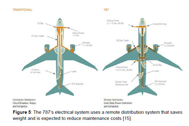
The old electrical architecture used to operate at 400Hz which could cause very high inrush current during the start of an induction machine [13]. Through power electronics converter we can replace less efficient and larger induction machines with more efficient and smaller permanent magnet motors [17] thus increasing fuel efficiency. In modern air-crafts such as the Boeing 787, for improved efficiency, the output of the cabin pressurization compressors flows through low-pressure air-conditioning packs. The adjustable speed feature of electrical motors will allow further optimization of aeroplane energy usage by not requiring excessive energy from the supplied compressed air and later regulating it down through modulating valves resulting in energy loss [15]. Traditionally centralized power distribution system, as shown in Figure 5, is used, where power is generated on wings.
With the increasing use of solid-state power controllers and contactors, it is becoming feasible to distribute power near the site of generation [13]. As the distance between generators and loads decrease line losses decrease and so does the rating of the main conductor thus resulting in a decrease of the overall weight of aircraft.
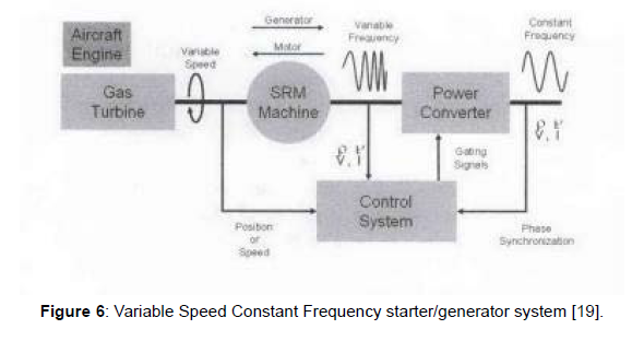
The first variable frequency system used in A380 simplified constant speed mechanical gearbox [18]. Due to Variable Speed Constant Frequency (VSCF) starter/generator architecture, shown in Figure 6, the constant frequency loads are fed through power electronics converter. In MEA, variable frequency generation will increase reliability by about 50% [19].
Need to dismantle the drives for maintenance purpose is eliminated, if online condition monitoring is enabled which will reduce risk of reassembling the drives incorrectly [20] making MEA comparatively safer.
Wing ice protection system
Ice on air-craft wings can hamper the aerodynamic lift of the aircraft and may cause it to stall. Apart from existing electrical loads functions like, starting the engine and providing power to passenger environment control, Wing deicing/anti-icing can also be added to the electrical system, by replacing the existing pneumatic system, which will eliminate the need of various parts such as ducts, control valves and pre-coolers which will ultimately reduce the downtime and the weight of the aircraft [21].
There are two ways to protect wings from ice, which are antiice and de-ice. Anti-icing is a preventive measure which avoids the buildup of ice, whereas de-icing removes already built up ice on wings. In conventional air-craft architecture, pneumatic power is provided to the wing ice protection system, which is extracted from the engines in the form of bleed air [21], which burdens the engines and hampers their efficiency.
The more electrical architecture includes a blanket heating system (loads in the form of resistors) attached to leading edges and are energized for anti-icing/de-icing functions [21]. Although electrical power generation required per engine is less in traditional air-craft as hydraulics, environmental control and de-icing/anti-icing are not powered by electricity, electrical wing ice protection system, utilize half of the power utilized by the pneumatic system [15] and, make a lucrative option because of weight and noise reduction.
Progress is being made in the field of more efficient ice protection system such as a pulse electrothermal de-icing system, which is expected to save 99% of the energy consumed by the conventional thermal deicing system [22].
Elimination of integrated drive generator (IDG)
IDG in the conventional air-craft system is used to obtain constant speed from variable speed of the engine through mechanical means so that frequency can be maintained at a constant level. It has proven to be maintenance-intensive and requires to be replaced frequently. In modern commercial jets need of IDG has been eliminated, as in MEA systems move towards variable frequency. The generator/starter now is directly coupled with the engine and, constant frequency loads are fed via power electronic converters.
Goods of fungicide types on ecosystem function
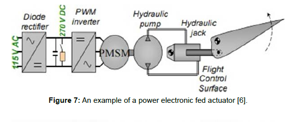
The hydraulic system in a conventional architecture consists of namely three systems Green, Yellow and Blue. Green and Yellow hydraulic system burden the engine by drawing power from the engine-driven pumps whereas the Blue hydraulic system is run by electric power. The hydraulic system is used for primary and secondary surface controls such as braking, landing gears, doors, reverse thrust engine control etc. Major drawbacks of such a system are less efficiency and bulky infrastructure. It is inefficient in detecting leaks and also conjures the risk of fire due to leakage of flammable hydraulic liquid [21]. In MEA, EHA system is utilized which is a distributed hydraulic system and operates individual small hydraulic pumps, [18] which can be isolated in case of failure or emergency.
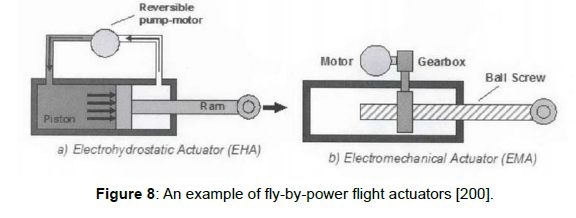
As depicted in Figure 7 EHA is a self-contained unit which eliminates the need for fluid tank, piping and external hydraulic source. EHA contains various parts such as a hydraulic cylinder, a power module and a mounting interface with the device being driven. The hydraulic oil is sent to the cylinder from power module according to required position of the connected device (there are two ways of implementing EHA which are by, using an electric motor with variable speed and fixed displacement hydraulic pump or using a motor with fixed speed and variable displacement hydraulic pump [23])
This more electrical architecture is comparatively more beneficial as localized pumps draw power only when there is a need, such as during aircraft making a bank. Whereas hydraulic system act as continuous load, affecting the efficiency of the engine. EMA, depicted in Figure 8, moves the actuator through roller-screw which is operated by a permanent magnet synchronous motor [19] and, is more efficient because it can run the hydraulic pump in reverse as well, as it uses gearbox for linear motion in place of hydraulic power [18]. EMA forms a decentralized system as compared to a centralized system involving EHA and, is less maintenance intensive as compared to EHA. EMA also eliminates the of the need of hydraulic fluid, which adds to the weight of aircraft [18] and, involves lesser initial cost. Thus EHA or EMA system reduces weight and improves the fuel efficiency of the aircraft.
A fault anticipating software can be developed to detect faults early on in EMA, thus making it a safer option for primary flight controls as well [20].
With help of an aircraft performance model, replacing the hydraulic system with more electric technologies resulted in minimum, 0.1%, 0.1% and 0.25% reduction in Operating Empty Weight (which is the standard basic weight of an aircraft), of Airbus A330-200, A380-100 and A340-500 respectively [8].
Bleed air
The bleed-air architecture of conventional air-craft results in less efficiency of the engines. Non-thrust power of conventional air-craft is approximately 1.74MW, which is 74% higher than that of MEA [24]. In the no-bleed system of the aircraft, instead of tapping bleed air from the engine for the environmental control system, compressors running on electrical energy is used to regulate temperature and pressure so that engine can use saved bleed air for more thrust production and result into lower consumption of fuel and extended range of operation. As bleed air from the engine is not being utilized for non-thrust purposes, pneumatic systems are eliminated thus reducing the weight of the aircraft and toxic hazards, for passenger, such as the risk of oil leakage, which can enter the cabin through air ducts in form of smoke, is eliminated. As such there is no sensor installed, in the current system of conventional air-craft, to detect this oil leak apart from natural smell sense of pilots. By installing no-bleed architecture in MEA it has been observed that up to 35% less power is drawn as compared to conventional air-craft [15].
Drawing less power means less fuel consumption and also the elimination of ducts contributes in reducing the weight of the aircraft. This architecture can lead to up to 2% saving in fuel consumption, while on cruise mode [18]. By utilizing electric compressors and eliminating the need of bleed air for cabin pressurization and temperature control, we can obtain more efficient secondary power transfer and maintenance costs can be reduced(because this system uses lesser number of parts) [15]. Efficient secondary power transfer could save up to 3% fuel as compared to a conventional air-craft system [18]. Air-craft energy can be thoroughly utilized by using motors, employed in compressor and fans to circulate air, which have controllable speed characteristics.
By utilizing aircraft performance model it was observed that, substituting bleed air system and hydraulic system with more electric technologies, can result in fuel saving, up to 2.6%, 3.5% and 2.75% in A330-200, A380-100 and A340-500 air-crafts respectively [8].
Electric taxiing
An air-craft is pushed out of the terminal using a tug vehicle, after which it uses engine thrust to taxi till runway. At major hub airports, taxiing can consume a large amount of time due to traffic and long distances to reach the runway, for example, flights spend an average of 40 minutes in taxiing at JFK [25]. Meanwhile, engines produce very less thrust and are idle for most of the time, burning up a significant amount of fuel. Till the time an aircraft is on the ground, it can consume up to 3% of the total amount of fuel to be used in flight [26]. MEA architecture proposes using motors embedded in landing gears to be used for taxiing, so that engines can be started shortly before takeoff so that they run for a shorter time and consume less fuel. Air-crafts employing this architecture can have a faster push-back [26] saving time and cost for the carrier. After landing too, motors can drive the aircraft till gates meanwhile shutting off the engines and saving fuel and emissions. Cost and emissions (unless electric) of tug-vehicle can also be eliminated.
Electric taxi system requires conditioned power from the APU to be fed to traction motors using power electronic converters. If alternate sources of energy such as fuel cells are used, taxiing has the potential to become completely emission-free [13].
Future possibilities
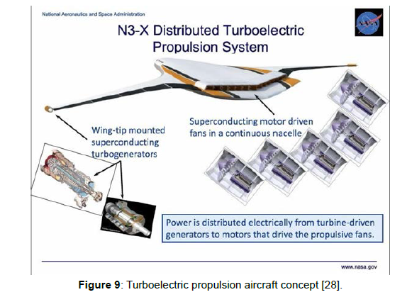
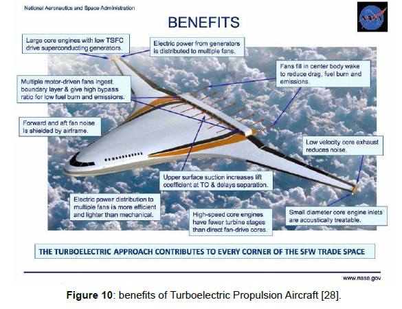
The goal of MEA is to ultimately move towards an All-Electric Aircraft (AEA). Currently, a ten-seater all-electric aircraft with a range of about 100 miles is possible [25]. Airbus is testing a 4 engine aircraft with one of the engines replaced by a 2.5MW electric engine driving a fan [25].To curb noise pollution and to achieve fuel efficiency targets, research is being undertaken in the field of open rotor engines [27]. The number of enplanement by global airlines, in 2020, is expected to reach 4723 million thus efficient use of current small airports, with small runways, is becoming necessary. Turboelectric propulsion aircraft presents a promising area of research, which have better aerodynamic capability allowing shorter take-off and landing. It also protects people on the ground from noise, thus causing less noise pollution in urban areas. Turboelectric propulsion concept, Figure 9, includes two wingtip
mounted generators which provide high electric power to the fan motors which operate at very high efficiency; It makes a lucrative option for freight hauling. These air-crafts could operate from smaller airports thus decreasing, layover time and crowd at major hub airports. Further technical and aeronautical advantages are depicted in Figure 10.Conclusion
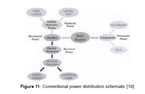
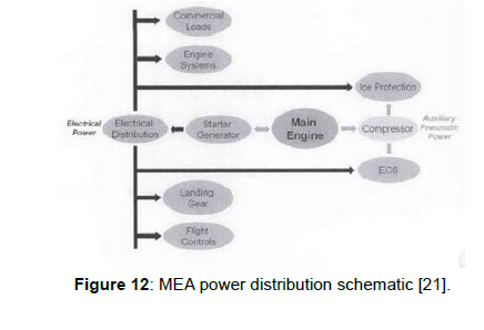
Commercial aviation has seen dramatic growth and, the numbers are expected to rise even further. When we account the emissions this industry emits, with the continuously rising number, we realize that the challenge we are facing is huge. There is worldwide effort to curb climate change and reduce emissions, and MEA is an effort through which commercial aviation industry can make its contribution. MEA is not only more environmentally conscious but also acts towards saving costs and time for the carriers. Weight is a very important parameter for an aircraft. Every kilo of weight flying has a cost attached to it which generally is in the form of increased fuel consumption. Technological advancement has made possible to replace bulky and comparatively inefficient parts of an aircraft with electrical or electronic parts which are smaller, lighter and more reliable. Figure 11 and Figure 12 represent the possible and desirable changes that can be made in traditional
architecture in order to achieve these goals. Table 2 summarizes| MEA | Advantage |
|---|---|
| Higher Voltage level | Reduces weight and cost |
| Power generated at variable frequency | Increases fuel efficiency, Reduces weight and cost |
| Starter/Generator system | Improves reliability, Reduces weight; increases fuel efficiency, Makes external equipment redundant |
| Power electronic converters | Increases efficiency, Reduces weight; improves fuel efficiency, Saves energy, Increases reliability, Improves safety |
| Electric Wing Ice Protection System | Less number of parts, Reduces downtime, Reduces noise, Reduces weight; Improves fuel efficiency |
| Elimination of IDG | Reduces maintenance cost, Reduces downtime, Reduces weight; Improves fuel efficiency |
| EHA or EMA | Improves safety, Increases system efficiency, Increases engine efficiency, Decreases maintenance cost and time |
| No-Bleed air | Increases thrust, Extends the range of operation, Reduces weight, Improves safety(oil leak), Reduces fuel consumption |
| Electric taxiing | Saves fuel, Saves carrier’s cost and time, No need for tug vehicle, Reduces emissions |
Table 2: MEA technologies and their advantages.
the environmental advantages of each component of More Electric Aircraft. Intense research is being undertaken across the industry to make the “aircraft of the future” and few such current examples are Boeing 787 or an Airbus A380. MEA is a step towards totally emissionfree All-Electric Aircraft.
References
- Graver B, Zhang K, Rutherford D (2018) CO2 emissions from commercial aviation.
- Climate footprint: 4.5 per cent decrease in greenhouse gas emissions.
- Climate change: Commission proposes bringing air transport into EU Emissions Trading Scheme. (2006).
- UN emissions gap report 2019
- Bose BK (2013) Global Energy Scenario and Impact of Power Electronics in 21st Century IEEE. Transactions on Industrial Electronics.
- Roboam X (2011) New Trends and Challenges of Electrical Networks Embedded in "More Electrical Aircraft” IEEE.
- Feiner LJ (1994) Power electronics transforms aircraft systems. Proceedings of WESCON.
- Laskaridis, Panagiotis (2004) Performance investigations and systems architectures for the More Electric Aircraft.
- Naayagi RT (2013) A review of more electric aircraft technology. 2013 International Conference on Energy Efficient Technologies for Sustainability.
- Zhao X, Guerrero JM, Wu X (2014) Review of Aircraft Electric Power Systems and Architectures. IEEE International Energy Conference. ENERGYCON proceedings.
- Emadi K, Ehsani M (2000) Aircraft power systems: technology, state of the art, and future trends. IEEE Aerospace and Electronic Systems Magazine
- Christou I, Nelms A, Husband M, Cotton I (2011) Choice of optimal voltage for more electric aircraft wiring systems. IET Electrical Systems in Transportation.
- Bulent Sarlioglu, Casey T. Morris More Electric air-craft – Review, Challenges and Opportunities for Commercial Transport air-craft. IEEE Transactions on Transportation Electrification.
- Schwalm GK (2007) On-Board inert gas generation system. U.S. Patent.
- Sinnet M (2007) 787 No bleed: saving fuel and enhancing operational efficiencies Boeing Aero Magazine.
- Serhiy Bozhko, Tao Yang, Jean-Marc Le Peuvedic, Puvan Arumugam, Marco Degano, et al. (2018) Patrick Wheeler Development of Aircraft Electric Starter-Generator System Based-On Active Rectification Technology. IEEE Transactions on Transportation Electrification.
- Steve Bistak, Sun Y Kim (Sean). AC Induction Motors vs. Permanent Magnet Synchronous Motors.
- Shaw JC, Fletcher SDA, Norman PJ, Galloway SJ (2012) More electric power system concepts for an environmentally responsible aircraft (N+2).
- Rosero JA, Ortega JA, Aldabas E, Romeral L (2007) Moving towards a more electric aircraft. IEEE Aerospace and Electronic Systems Magazine.
- Garcia A, Cusido J, Rosero JA, Ortega JA, Romeral L (2008) Reliable Electro-Mechanical Actuators in Aircraft. IEEE A&E Systems Magazine.
- Imayavaramban Munuswamy, Patrick W Wheeler (2017) Electric DC WIPS: All Electric Aircraft. International conference on innovation in power & advanced computing technologies (I-PACT2017).
- Petrenko VF, Sullivan CR, Kozlyuk V, Petrenko FV, Veerasamy V (2011) Pulse electro-thermal de-icer (PETD). Cold Reg Sci Technol 65: 70-78.
- Cutts SJ (2002) A collaborative approach to the More Electric Aircraft. International Conference on Power Electronics Machines and Drives.
- Yitao Liu (2018) Energy optimization analysis of the more electric aircraft. Earth Environ Sci 113: 012152.
- Greener by design - annual report 2018-19, Royal Aeronautical Society
- Oyori H and Morioka N (2013) Power management system for the electric taxiing system incorporating the more electric architecture. SAE Technical Paper.
- McLoughlin A (2009) Engine Powerplant Electrical Systems Rolls Royce Plc.
- Brown, Gerald V (2009) Materials Aspects of Turboelectric Aircraft Propulsion Presenter. Atlanta, GA, United States, NASA.
Indexed at, Google Scholar, Crossref
Indexed at, Google Scholar, Crossref
Indexed at, Google Scholar, Crossref
Indexed at, Google Scholar, Crossref
Indexed at, Google Scholar, Crossref
Indexed at, Google Scholar, Crossref
Citation: Pathak A (2022) More Electric Aircraft for Greener Aviation (A Comparative Study). Environ Pollut Climate Change 6: 292. DOI: 10.4172/2573-458X.1000292
Copyright: © 2022 Pathak A. This is an open-access article distributed under the terms of the Creative Commons Attribution License, which permits unrestricted use, distribution, and reproduction in any medium, provided the original author and source are credited.
Select your language of interest to view the total content in your interested language
Share This Article
Recommended Journals
Open Access Journals
Article Tools
Article Usage
- Total views: 3651
- [From(publication date): 0-2022 - Dec 05, 2025]
- Breakdown by view type
- HTML page views: 3181
- PDF downloads: 470

