Modification of Isomerization Process at PGSOC1 to Improving Research Octane Number
Received: 01-Aug-2023 / Manuscript No. jabt-23-105658 / Editor assigned: 03-Aug-2023 / PreQC No. jabt-23-105658 (PQ) / Reviewed: 17-Aug-2023 / QC No. jabt-23-105658 / Revised: 21-Aug-2023 / Manuscript No. jabt-23-105658 (R) / Accepted Date: 25-Aug-2023 / Published Date: 28-Aug-2023 DOI: 10.4172/2155-9872.1000557
Abstract
Research Octane Number (RON) of the Light Naphtha Isomerization (LNI) process affected the quality of gasoline and RON, that one of the most important issues in the refinery. In this research, the isomerization unit in an existing 480,000 bbl/day gas condensate refinery has been studied to increase the RON and decrease the total cost. The study involved selecting the equipment to replace them in an isomerization unit used to improve RON and decrease total costs for specific feed. The DIP-DIH isomerization unit was selected as a base case. Three scenarios were studied and simulated to predict the product specification. These scenarios included DIP-DP, DIP-DH, and DIP-DP-DH isomerization units. To increase RON, we designed and simulated these scenarios by Aspen HYSYS V9, and to study the energy consumption of the Heat Exchanger Network (HEN) used Aspen Energy Analyzer. The results show that by adding and replacing new equipment the RON and total cost were changed. The DIP-DP isomerization unit has a higher multiply flow rate by RON, rather than the base case (DIP-DIH) and other scenarios. The result indicated that DIP-DP isomerization improves RON and total cost by 6.6% and 7.9 %.
Keywords
Isomerization; Research octane number; Simulation; Aspen HYSYS; Modification
Introduction
The purpose of the isomerization process is to increase gasoline quality and decrease environmental issues. The interest in the isomerization process has grown to limit the amount of benzene, aromatic, and olefin in gasoline to improve the Research Octane Number (RON). The isomerization process converts the liner hydrocarbon to the branched hydrocarbon. The isomerization process has been commercialized due to its wide application to gasoline production with high quality by some commercial technology the most important are GTC, Axens, and UOP. The isomerization process used column distillation like De-iso-pentanizer (DIP), De-iso-hexanizer (DIH), De-hexanizer (DH), and De-pentanizer (DP) for separation of hydrocarbon to achieve the highest RON. DIP increases the driving force with the separation of iso-pentane from the feed. The situation of DIP before the reactor causes to increase in the RON increases the normal pentane conversion and reduces the duty of the reactor. Add the DP column after the reactor and reverse normal pentane to the reactor, the reactor separation the iso pentane while converting normal pentane to iso pentane, and finally increases the RON. To increase the iso-hexane, reverse the normal hexane and methyl pentane to the reactor and convert to their isomers using the DH after the reactor. Proposed a new isomerization process and evaluated and compared the efficiency of their process with eight industrial isomerization processes in RON, efficiency, and cost using basic model optimization techniques. They realized that adding the DIP column has a positive effect on RON, product, and operating costs. M. Shehata, have performed 8 retrofitting models to predict product specifications. Other modification equipment has been added to separate iso-pentane and to convert pentane. Their results show changes in the gasoline RON for a specific feed. Feed composition like naphthenic and benzene content and also operation condition like temperature, hydrogen consumption, and liquid hourly space velocity (LHSV) has been analyzed and optimized on an isomerization unit by M. Shehata et al. They understand that an increase in the feed benzene and naphthenic due to more hydrogen consumption and extra reactions cause the reduction of the production quality. The production quality increase with the increase in temperature and decrease of LHSV. Zhao et al. esteemed the new process for ultra-clean gasoline production by a unique separation method. The composition was separated by distillation and solvent extraction, that separation yield was related to solvent and feedstock composition. Simulation of the process is carried out by Aspen plus. Energy optimization and yield in the reforming process were carried out by process improvement to increase reformate and save energy by Badiea. They understand two improved opportunities were exciting, the first was an increase in production by improving the reactions network and separation process, and the second was saving energy in the heat exchanger network by pinch analysis. Their results show an increase in production by 7800 T/y and a decrease in energy saving by 98.81 Gj/h. Malfi investigated the optimization of the control parameters on separation, the simulation of the splitter, and the comparison between the design and the actual. Some studies in the LNI unit on RON were carried out by Can. Also, some investigations on reaction and catalysts in LNI units were studied by PGSOC, is the biggest refinery in the Middle East, and the biggest refinery with condensate gas feed in the world, located in the South of Iran, Bandar Abas. PGSOC was established in 2006 and all three phases became operational in 2018 despite sanctions. The total gas condensate feedstock to the refinery was designed at 360,000 BPSD and now is operating at 480,000 bbl/ day of the design. PGSOC includes Column Distillation Unit (CDU), Naphtha HydroTreater (NHT) unit, Octanaizer and Continuous Catalytic Regeneration (CCR) unit, liquid Pressure Gas (LPG) unit, Isomerization unit, Kerosene HydroTreater (KHT) unit, and Gas Oil HydroTreater (GOHT) unit which produces Gasoline, Gas oil, LPG,Kerosene with 5 Euro standard. The feed is supplied by the pipes of South Pars Gas Refinery. Before the establishment of PGSOC, all gas condensate was sold in the market and the Iranian government had to import gasoline to meet its needs. PGSOC is the first gas condensate refinery in Iran. By exploiting all three phases of PGSOC, the Iranian government exports gasoline to other countries. Thus, operating the PGSOC is very important in Iran and in the Middle East. The extra value of gas condensate refineries is more than oil refineries, and on the other hand, the production of gasoline and gasoil from gas condensate refinery more than 75% from feed, is one of the economic justifications of this company. The first time, we studied the RON of the LNI process at PGSOC in this research. Up to now, there aren’t any research studies on the RON of LNI at PGSOC, which are fed with gas condensate. Also, there are a few investigations on the RON of LNI of the refinery with gas condensate feed. Thus the retrofitting and optimization of the LNI unit in this refinery is very important and necessary. The LNI unit is licensed by UOP Company with the Penex process. This study investigates the isomerization process (DIP-DIH) to increase RON by simulation with Aspen HYSYS V9 software. For this purpose, three scenarios that included DIP-DP, DIP-DH, and, DIP-DP-DH were studied and compared with the base case in RON and total cost. These scenarios investigated the process by adding, removing, or substituting the process equipment.
Process description
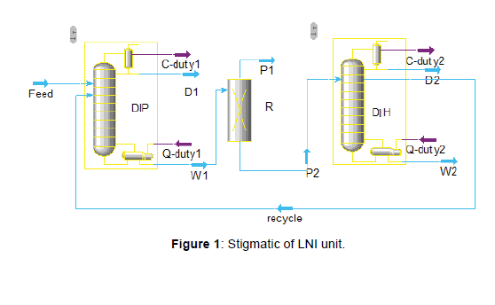
The feedstock at PGSOC is gas condensate that lighter than crude oil, it means the heavy hydrocarbon (𝐶+) is the less and the light hydrocarbon is the more in gas condensate [1-7] feedstock. Also the product specification of gas condensate, like RON, benzene, and Sulphur, is better than crude oil feedstock. In this research, the LNI unit is licensed by the UOP Penex process. The Penex process has served as the primary isomerization technology for upgrading C5/ C6 light straight-run naphtha feeds since 1958. Penex process in the feedstock stream can bear up to 5 vol% benzene. The Penex/DIH Process Units shall be designed to each process 30,000 BPSD of light naphtha derived from South Pars condensate. The three-phase Penex/ DIH Process Units shall each include a Deisopentanizer Column (DIP) and a Deisohexanizer Column (DIH). The DIP will produce an overhead product rich in isopentane and the bottoms will be routed to the Penex reactor section. The DIH will produce overhead and bottom products, as well as a recycle stream which shall be routed back to the reactor section to maximize the product RON, that indicated in (Figure 1). The DIP overhead product when mixed with the DIH overhead and bottoms product, will form the isomerate product (Figure 1).
The feed to the Penex/DIH process units is light straight run naphtha and derived directly from the overhead system of a Naphtha splitter that has the properties in (Tables 1 & 2). The isomerization unit consists of these sections: DIP Section, Feed and make-up gas driers, Reactor exchanger circuit, Isomerization reactors, Stabilizer, Net gas scrubber, DIH, and Methanator.
| Component | wt% | Component | wt% |
|---|---|---|---|
| n-Butane | 0.01 | 3-Mpentane | 6.84 |
| i-Pentane | 22.25 | n-Hexane | 15.59 |
| n-Pentane | 21.58 | Mcyclopentan | 5.85 |
| Cyclopentane | 1.22 | Cyclohexane | 3.3 |
| 22-Mbutane | 1.28 | Benzene | 6.08 |
| 23M-1-butene | 2.05 | C7+Paraffins | 2.11 |
| 2-Mpentane | 11.45 | C7+Naphthenes | 0.39 |
| Total | 100 | Flowrate Kg/hr | 132296 |
Table 1: Feedstock component to the isomerization unit.
| Contamination | Value |
|---|---|
| Total sulfure, ppm | 0.5 |
| Total nitrogen, ppm | 0.1 |
| Bromine number | 4 |
| Total oxygenate | 0.5 |
| Hcl, ppm | 0.5 |
| Fluoride,ppm | 0 |
| Copper, ppb | 20 |
| Lead, ppb | 10 |
| Arsenic, ppb | 1 |
| Mercury,ppb | 1 |
Table2: Feedstock component to the isomerization unit.
DIP section
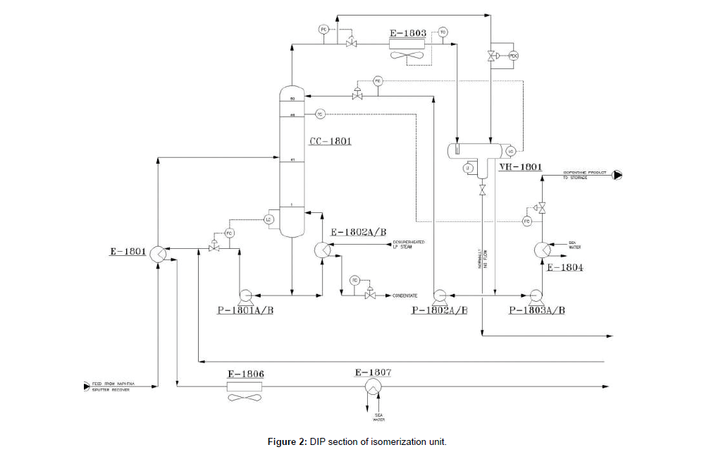
The light Naphtha with the temperature of 40ºC and pressure of 6 barg, will be entered to DIP column (CC- 1801) through E-1801. The purpose of this column is to remove isopentanes with a high RON from the reactor feed. In order to maximize the product RON, the recycle stream will be routed back from DIH side draw pumps and will be mixed with DIP bottom product to route to the feed drier section after cooling through E-1801, E-1806, E-1807 down to 40°C. The DIP section shown in (Figure 2).
Feed and make up gas driers
Due to the extreme sensitivity of the Penex catalyst with water and other containments, the feedstock and the makeup hydrogen for the Penex unit must be routed through molecular sieve driers. These driers are designed to remove containments before they can reach to the Penex catalyst and deactivate the catalyst.
Liquid feed drier
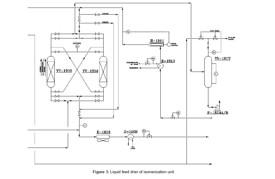
The liquid feed driers that showed in (Figure 3) are loaded with molecular sieves adsorbent HPG-250 for the removal of water and trace levels of oxygenates or sulfur compounds. The hydrotreated stream is introduced to liquid feed drier (VV-1805, 6) at the bottom and passes upflow through the molecular sieve desiccant and exits at the top. The dried hydrocarbon is then routed to feed surge drum (VV- 1807) (Figure 3).
Makeup gas drier
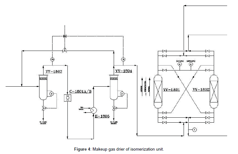
To remove any liquid drops the cooled gas is sent to VV- 1804 and then sent to the gas driers. Makeup gas must be dried to remove water and potential CO⁄CO2 which are extremely poisonous to the reactor catalyst. The driers operate up flow, in series. The dried hydrogen is then sent to the reactor circuit (Figure 4).
Regeneration
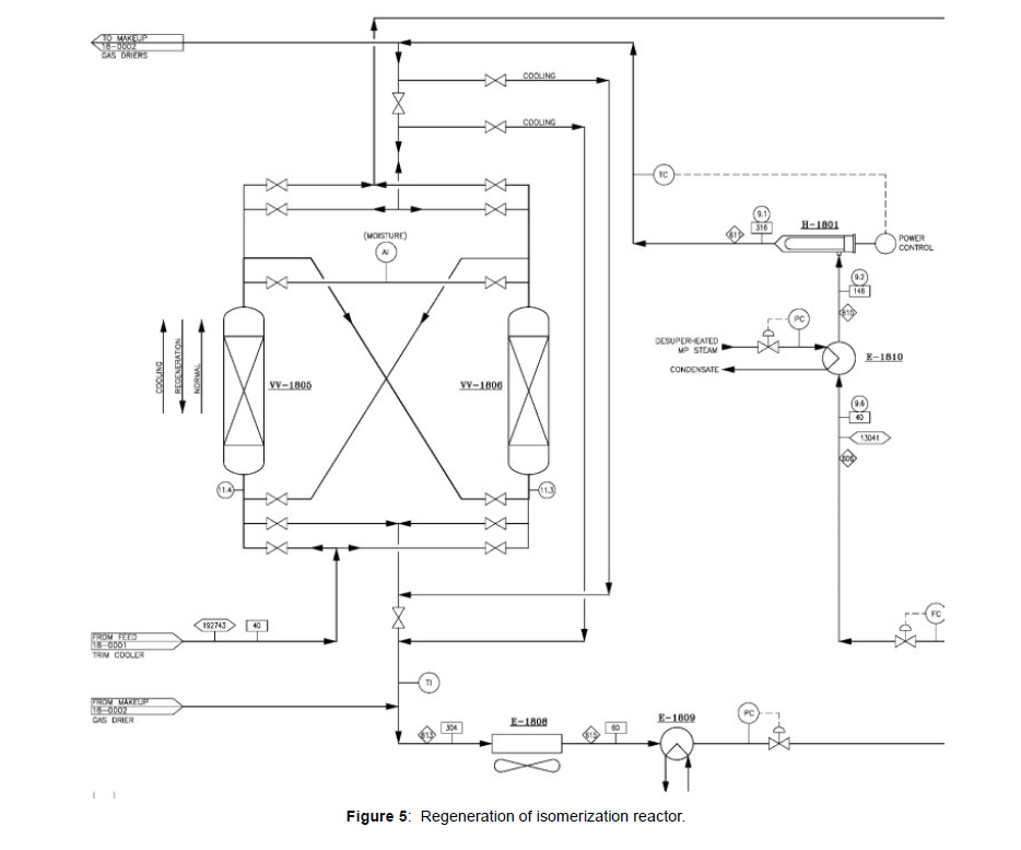
A part of the isomerate, DIH overhead liquid product is used for driers regeneration, as shown in (Figure 5). The regenerant vaporizer E-1810 is used to heat the regenerant stream before it reaches the electric superheater (H-1801). The regenerant enters to spent drier (feed or gas dryer). Regenerant is flow down from the drier and absorb moistures and other contaminates from molecular sieves. Spent regenerant from driers are combined and cooled through E-1808 and E-1809 and back to product line to join the material sent to storage (Figure 5).
Reactor exchanger circuit
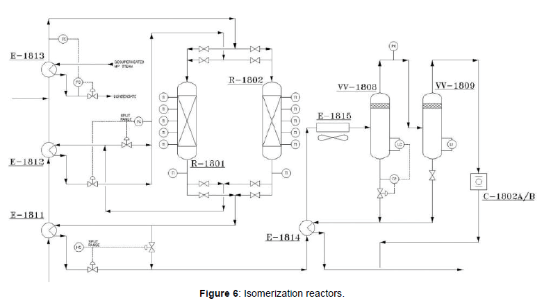
The reactor exchanger circuit consists of the cold combined feed exchanger (E-1811), the hot combined feed exchanger (E-1812) and the reactor charge heater (E-1813). Prior to the entry of the liquid hydrocarbon into the cold combined feed exchanger, it combines with the makeup and recycles hydrogen streams. After exiting the reactor charge heater, the heated combined stream then flows to the first reactor.
Isomerization reactors
The Penex system employs two reactors in a series flow configuration. The catalyst type is “Amorphous Chloride Alumina containing platinum”; “I-8 catalyst. Isomerization and Benzene hydrogenation reactions are both exothermic and the temperature increases across the reactor. Upon exiting the first reactor, the stream then passes to the hot combined feed exchanger (E-1812). The partially cooled stream is then routed to the second reactor (R-1802). Upon exiting the second reactor, the stream then passes to the cold combined feed exchanger (E-1811) to remove heat of reaction at the second reactor (Figure 6). The liquid outlet of the separator enters to the stabilizer.
Stabilizer
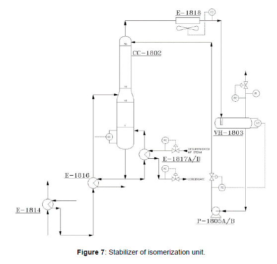
The purpose of this column (CC-1802) is to separate any HCl and light cracked gases (C1, C2, and C3’s) from the isomerate that shown in (Figure 7). The feed to this column is first preheated in (E-1814) and (E- 1816) before entering the stabilizer. The stabilizer column overhead vapor, consisting of the light hydrocarbon components of the column’s feed, is routed to the net gas scrubber after cooling. Bottoms product is routed to DIH column.
Net gas scrubber
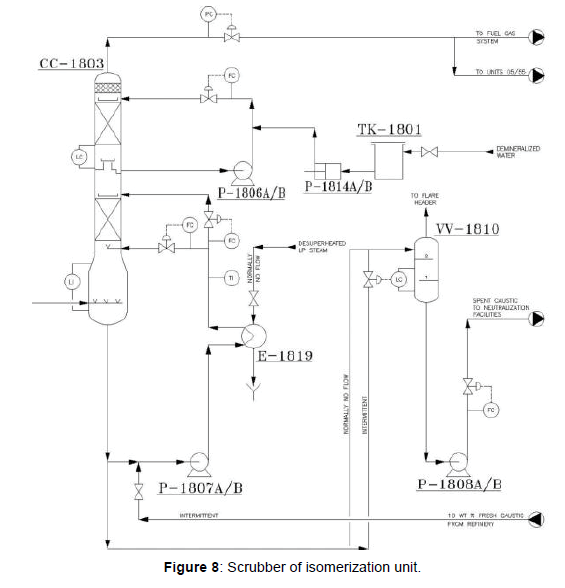
The function of the Net Gas Scrubber (CC-1803), as indicated in (Figure 8) is to neutralize the hydrogen chloride HCl present in the stabilizer off gas. In this vessel, the off gas is contacted with a counter current flow of caustic solution (10 wt% NaOH) which reacts with HCl to form sodium chloride and water.
DIH
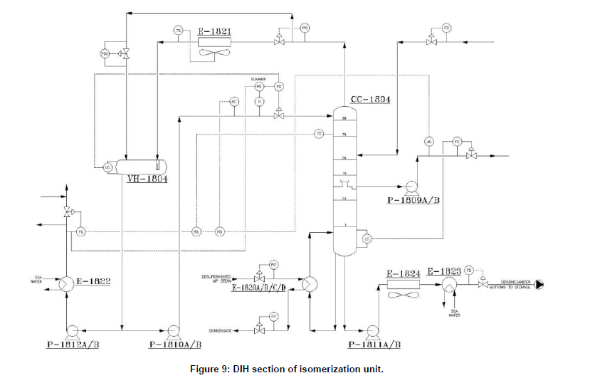
The purpose of this column (CC-1804) is to recover product isohexane and pentanes from the stabilized reactor products. The overhead product which is mainly C5’s and di-methylbutanes is sent to isomerate storage. The bottoms product from the column is generally a small and is sent to storage. The DIH recycle stream is taken off as a lower side cut. Since the RON of 2MP and 3MP is lower than 2-2DMB and 2- 3DMB, then DIH column is designed to limit the amount of methyl-pentanes in the isomerate and recycle back them to the rector section as lower side cut. The lower side cut is pumped back, and mix with the DIP bottom to enter to Penex liquid feed driers. The majority of the cyclo-hexane and 𝐶+ material should be rejected out the bottom of the tower. DIH section indicated in (Figure 9).
Methanator
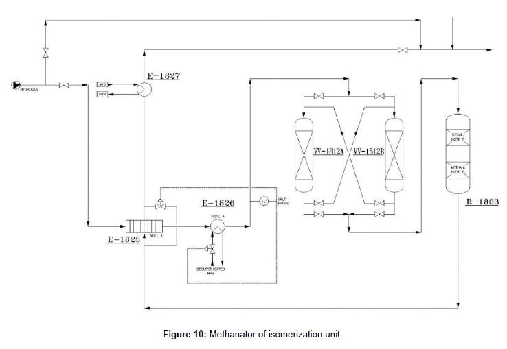
Methanator system is provided for removal of CO and CO2 from the hydrogen rich gas. Make up hydrogen feeds from the Octanaizer unit have some contamination that summarized in (Table 3). By installation of a methanator system the values of CO will be decreased to 1 mol.ppm max, that shown in (Figure 10). The main equipment of the methanation system is R-1803. This reactor includes two sections: one for desulphurization and anothre for methanation. To protect the catalysts of the R-1803, HCl guard beds are considered at the upstream. Hydrogen is warmed through methanator feed/effluent exchanger (E 1825), plate type, and E-1826 up to 210ºC. Heat input to the mentioned exchangers is provided by the methanator reactor outlet and High pressure Steam (HPS), respectively. The methanation reaction is exothermic and the temperature will increase about 3ºC through the reactor. The reactor outlet will be cooled down to 40ºC through E-1825 and E-1827 routed to make up gas driers section.
Contamination |
value |
|---|---|
| HCL | 0.5 mol ppm |
| sulfur | 1mol ppm |
| nitrogen | 1 mol ppm |
| Co | 25 mol ppm |
| Co2 | 35 mol ppm |
Table 3: contamination on Makeup hydrogen feeds.
Methodology
To design a distillation column by Aspen HYSYS, first, determine the column pressure, adjust the condenser and reboiler pressure, and the type of condenser (total or partial). Then the number of trays in the column is determined according to the minimum reflux to the column. In the final step, to simulate the column, the exact solution method is used. The condenser pressure at the top of the [1 -6] column is usually adjusted so that the condensate is cooled by sea water or air. Also, the reboiler pressure at the bottom of the column is adjusted so that the liquid is heated by steam. Column pressure is obtained to simulate the component splitter and select a case study in Aspen HYSYS. After determining the distillation column pressure and the type of condenser, the minimum number of equilibrium theory steps Nmin and the lowest return reflux Rmax can be estimated. Selecting the key components according to the composition separation. The degree of separation indicates the amount of LK in the bottom product of the column and the amount of HK in the top product of the column. By determining the amount of reflux, the optimum number of trays and heat duty of the condenser and reboiler can estimate. After that, the pressure at the top and bottom of the column and the location of the feed tray, simulate the column by the exact solution. In the distillation column, put the number of trays, the feed entry, and so on, to simulate the column. To reach the zero of freedom degree, 2 specifications of the column (for 2 streams production) are required.
Result and Discussion
The present study investigates the isomerization unit at PGSOC on RON and costs. Three scenarios were studied on the base case to compare the RON and costs. For this purpose, uses Aspen HYSYS V9 software to simulate the process, and Aspen Energy Analyzer V9 software to analysis the energy consumption and costs. All studied scenarios that involved base case and scenarios are presented in (Table 4), and each scenario simulates separately. All cases are based on the same feed flow rate and composition. The simulation was carried out, the whole analysis was obtained, and then RON and cost were calculated. The difference among these cases is based on the separation of iso-pentanes, n-pentanes, iso-hexanes, and n-hexanes and methylpentane. All cases separate high RON components and recycle the unconverted components to the reactor to reach the highest RON product. Here the scenarios were explained (Table 4).
scenarios |
Isomerization unit/Terminology |
|---|---|
| Base case | DIP-DIH |
| First scenario | DIP-DP |
| Second scenario | DIP-DH |
| Third scenario | DIP-DP-DH |
Table 4: The scenarios in isomerization unit.
Base case DIP-DIH
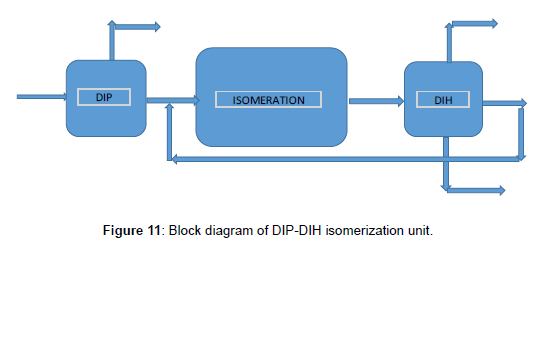
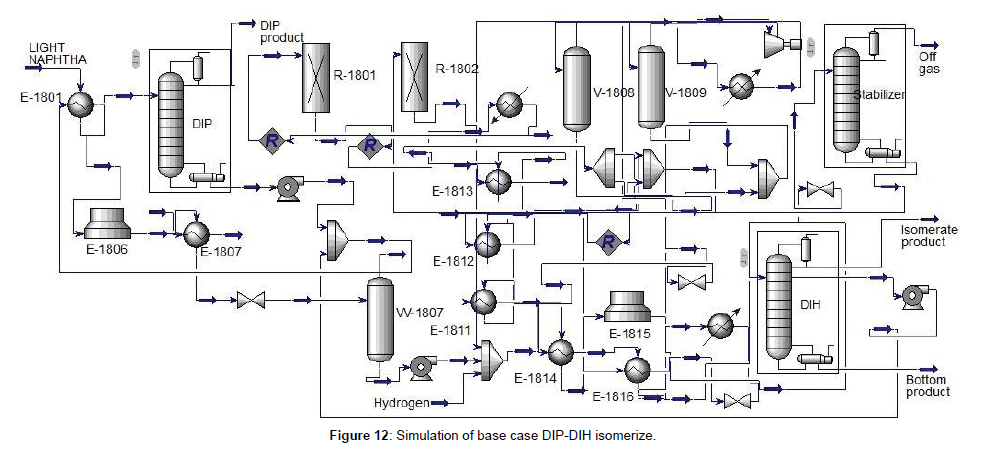
The base case isomerization unit consists of DIP, reaction section, stabilizer, and DIH, respectively. The block diagram of the base case was shown in (Figure 11). To confirm and compare the simulation with the design of the base case (DIP-DIH), first, simulate the DIP and the DIH column in detail by Aspen HYSYS V9. Using component splitter and case study to obtain the pressure, shortcut distillation to determine the 𝑁𝑚𝑖𝑛, and finally use an exact solution of the column. Simulation of the base case was indicated in (Figure 12), and specifications of the DIP and DIH column were summarized in (Table 5, Figures 11 and 12). DIP separate iso-pentane from feed and increase the driving force for the isomerization unit as a product. Due to the significant amount of iso-pentane in the feed of light naphtha, the DIP column for separating the iso-pentane is necessary. DIH column is used to separate the high RON from the products. The liner components are through back to the reactor from the middle of the DIH column.
Columns |
Trays number | Number of tray to inlet feed | Pressure of top of column (barg) | Pressure of bottom of column (barg) | Condenser Duty (MW) | Reboiler duty (MW) |
|---|---|---|---|---|---|---|
| DIP | 80 | 55 | 1.9 | 3.1 | 20.5 | 20.2 |
| DIH | 80 | 55 | 1.3 | 2.4 | 54.68 | 46.65 |
Table 5: Specification of DIP and DIH columns in the base case.
First scenario DIP-DP
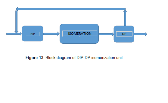
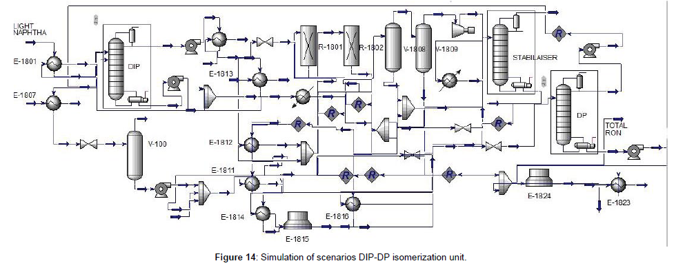
The first scenario isomerization unit that the block diagram indicated in (Figure 13), included DIP, reaction section, stabilizer, and De-Pentanizer (DP), respectively. The DIP column was simulated before, then in this scenario designed and simulated the DP column and then simulated the whole unit indicated in (Figure 14). To design of DP column, first, designed and simulated the [1-7] DP column in detail that was said before. The result shown, the number of trays was 61 which has the minimum duty of reboiler and condenser, and the minimum of total cost. The specifications of the DIP and DP column were indicated in (Table 6, Figure 13 and 14). In this scenario instead of DIH used DP to separate n-pentane and recycle via the DIP to increase the RON. The n-pentane was recycled to the DIP column to separate the iso-pentane from the feed and through the n-pentane to the reactor section. So that n-pentane converted to iso-pentane and as a result increases the RON. Simulation results for the isomerization unit with DIP-DP were indicated in (Table 7).
Columns |
Trays number | Number of tray to inlet feed | Pressure of top of column (barg) | Pressure of bottom of column (barg) | Condenser Duty (MW) | Reboiler duty (MW) |
|---|---|---|---|---|---|---|
| DIP | 80 | 55 | 1.9 | 3.1 | 20.5 | 20.2 |
| DP | 61 | 22 | 1.93 | 2.83 | 19.9 | 13.41 |
Table 6: Specification of DIP and DP columns in first case.
| DIP-DP | Feed | product from the top of DIP |
product from the top of DP |
product from the bottom of DP |
|---|---|---|---|---|
| H2O | 0.00 | 0.00 | 0.00 | 0.00 |
| Air | 0.00 | 0.00 | 0.00 | 0.00 |
| Hydrogen | 0.00 | 0.00 | 0.00 | 0.00 |
| Methane | 0.00 | 0.00 | 0.00 | 0.00 |
| Ethane | 0.00 | 0.00 | 0.00 | 0.00 |
| Propane | 0.00 | 0.00 | 0.00 | 0.00 |
| i-Butane | 0.00 | 0.71 | 0.71 | 0.00 |
| n-Butane | 13.37 | 4.23 | 4.00 | 0.00 |
| i-Pentane | 29436.17 | 706.37 | 302.58 | 0.01 |
| n-Pentane | 28549.43 | 22.00 | 149.94 | 7.00 |
| Cyclopentane | 1613.81 | 0.00 | 0.70 | 10.41 |
| 22-Mbutane | 1693.40 | 0.00 | 0.75 | 362.34 |
| 23M-1-butene | 2648.58 | 0.00 | 0.00 | 91.92 |
| 2-Mpentane | 15148.35 | 0.00 | 0.00 | 186.20 |
| 3-Mpentane | 9049.54 | 0.00 | 0.00 | 79.65 |
| n-Hexane | 20624.96 | 0.00 | 0.00 | 124.80 |
| Mcyclopentan | 7739.53 | 0.00 | 0.00 | 60.70 |
| Cyclohexane | 4365.38 | 0.00 | 0.00 | 79.43 |
| Benzene | 8042.99 | 0.00 | 0.00 | 0.00 |
| 2-Mhexane | 0.00 | 0.00 | 0.00 | 7.45 |
| 24-Mpentane | 2791.71 | 0.00 | 0.00 | 0.00 |
| Mcyclohexane | 0.00 | 0.00 | 0.00 | 51.02 |
| 11Mcycpentan | 515.49 | 0.00 | 0.00 | 0.00 |
| Toluene | 0.00 | 0.00 | 0.00 | 0.00 |
| 223-Mbutane | 0.00 | 0.00 | 0.00 | 0.00 |
| NaOH | 0.00 | 0.00 | 0.00 | 0.00 |
Table 7: Specification of DIP-DP isomerization unit.
Second scenario DIP-DH
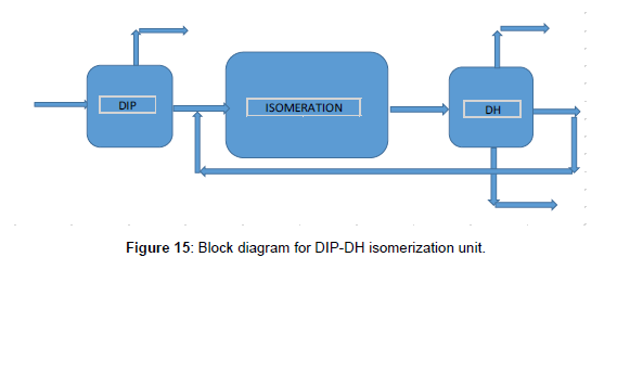
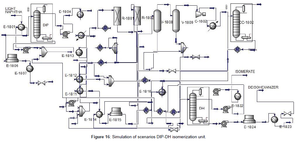
The isomerization unit of this scenario that the block diagram showed in Figure 15 included the DIP, reaction section, stabilizer, and De-Hexanizer (DH), respectively. The first design and simulated the DH column, after that the isomerization unit with DIP-DH has been simulated as indicated in Figure 16. To design of DH column, we carried out the same as before. The result showed that the number of trays was 80. The specifications of the DIP and DH columns are indicated in (Table 8, Figures 15 and 16). Feed with a significant iso-pentane component, was separated with a DIP column. Iso-pentane would pass on through unreacted and sent as a product. Other components from the bottom of DIP through to the reactor. Iso-pentane in the feed would limit the isomerization of pentane because of the equilibrium reaction. Then by separating the iso-pentane from the feed the driving force to convert the n-pentane to iso-pentane in the reactor was prepared. The DH column was used to separate the components with higher RON from the other component as products. DH can separate n-hexane and methyl-pentane from the product and through back to the reactor to convert the isomer form. All n-pentane and iso-pentane go overhead the DH. Simulation results for the isomerization unit with DIP-DH were summarized in (Table 9).
Columns |
Trays number | Number of the tray to inlet feed | Pressure of the top of the column (barg) | Pressure of the bottom of the column (barg) | Condenser Duty (MW) | Reboiler duty (MW) |
|---|---|---|---|---|---|---|
| DIP | 80 | 55 | 1.9 | 3.1 | 20.5 | 20.2 |
| DH | 80 | 24 | 1.0 | 1.78 | 64.2 | 33.6 |
Table 8: Specification of DIP and DH columns.
DIP-DH |
Feed | product from top of DIP |
product from top of DH |
product from bottom of DH |
recycle back to reactor |
|---|---|---|---|---|---|
| H2O | 0.00 | 0.00 | 0.00 | 0.00 | 0.00 |
| Air | 0.00 | 0.00 | 0.00 | 0.00 | 0.00 |
| Hydrogen | 0.00 | 0.00 | 0.00 | 0.00 | 0.00 |
| Methane | 0.00 | 0.00 | 0.00 | 0.00 | 0.00 |
| Ethane | 0.00 | 0.00 | 0.00 | 0.00 | 0.00 |
| Propane | 0.00 | 0.00 | 0.01 | 0.00 | 0.00 |
| i-Butane | 0.00 | 0.00 | 2.08 | 0.00 | 0.00 |
| n-Butane | 13.37 | 0.23 | 8.00 | 0.00 | 0.00 |
| i-Pentane | 29436.17 | 379.65 | 324.51 | 0.00 | 0.00 |
| n-Pentane | 28549.43 | 27.67 | 112.41 | 0.00 | 0.00 |
| Cyclopentane | 1613.81 | 0.00 | 10.84 | 0.00 | 0.00 |
| 22-Mbutane | 1693.40 | 0.00 | 361.92 | 0.00 | 0.02 |
| 23M-1-butene | 2648.58 | 0.00 | 91.45 | 0.52 | 9.99 |
| 2-Mpentane | 15148.35 | 0.00 | 174.54 | 14.13 | 183.05 |
| 3-Mpentane | 9049.54 | 0.00 | 12.45 | 27.27 | 166.08 |
| n-Hexane | 20624.96 | 0.00 | 0.23 | 64.83 | 126.70 |
| Mcyclopentan | 7739.53 | 0.00 | 0.02 | 45.01 | 46.81 |
| Cyclohexane | 4365.38 | 0.00 | 0.00 | 68.74 | 22.74 |
| Benzene | 8042.99 | 0.00 | 0.00 | 0.00 | 0.00 |
| 2-Mhexane | 0.00 | 0.00 | 0.00 | 7.45 | 1.04 |
| 24-Mpentane | 2791.71 | 0.00 | 0.00 | 0.00 | 0.00 |
| Mcyclohexane | 0.00 | 0.00 | 0.00 | 51.02 | 5.51 |
| 11Mcycpentan | 515.49 | 0.00 | 0.00 | 0.00 | 0.00 |
| Toluene | 0.00 | 0.00 | 0.00 | 0.00 | 0.00 |
| 223-Mbutane | 0.00 | 0.00 | 0.00 | 0.00 | 0.00 |
| NaOH | 0.00 | 0.00 | 0.00 | 0.00 | 0.00 |
Table 9: Specification of DIP-DH isomerization unit.
Third scenario DIP-DP-DH
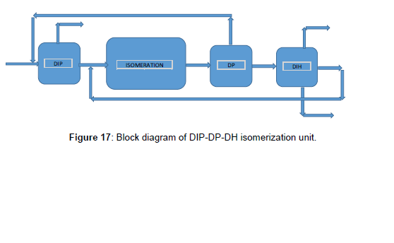
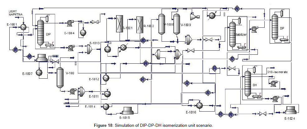
The block diagram of this scenario indicated in (Figure 17), included DIP, Isomerization reactor, stabilizer, DP, and DH, respectively. As said before, DIP was used to separate the iso-pentane from other components. An isomerization reactor with a stabilizer was situated to convert the liner form to a branched form of hydrocarbon and DP separates and recycles the unconverted pentane before the DIP. Used DH to recycle the n-hexane and methyl pentane by through back to the reactor. DIP, DP, and DH with isomerization reactor convert all liner paraffin to branched one and separate the component with high RON. Simulation and simulation results were shown in (Figures 17 and 18) and (Table 10).
| DIP-DP-DH | Feed | product from top of DIP |
product from top of DH |
product from bottom of DH |
recycle back to reactor |
|---|---|---|---|---|---|
| H2O | 0.00 | 0.00 | 0.00 | 0.00 | 0.00 |
| Air | 0.00 | 0.00 | 0.00 | 0.00 | 0.00 |
| Hydrogen | 0.00 | 0.00 | 0.00 | 0.00 | 0.00 |
| Methane | 0.00 | 0.00 | 0.00 | 0.00 | 0.00 |
| Ethane | 0.00 | 0.00 | 0.00 | 0.00 | 0.00 |
| Propane | 0.00 | 0.01 | 0.00 | 0.00 | 0.00 |
| i-Butane | 0.00 | 2.07 | 0.00 | 0.00 | 0.00 |
| n-Butane | 13.37 | 8.23 | 0.00 | 0.00 | 0.00 |
| i-Pentane | 29436.17 | 704.30 | 0.02 | 0.00 | 0.00 |
| n-Pentane | 28549.43 | 52.06 | 7.00 | 0.00 | 0.00 |
| Cyclopentane | 1613.81 | 0.00 | 10.45 | 0.00 | 0.00 |
| 22-Mbutane | 1693.40 | 0.00 | 362.21 | 0.00 | 0.04 |
| 23M-1-butene | 2648.58 | 0.00 | 91.48 | 0.55 | 10.00 |
| 2-Mpentane | 15148.35 | 0.00 | 177.75 | 9.33 | 115.30 |
| 3-Mpentane | 9049.54 | 0.00 | 26.29 | 22.65 | 132.58 |
| n-Hexane | 20624.96 | 0.00 | 0.91 | 64.64 | 125.73 |
| Mcyclopentan | 7739.53 | 0.00 | 0.08 | 45.00 | 46.83 |
| Cyclohexane | 4365.38 | 0.00 | 0.00 | 67.75 | 24.76 |
| Benzene | 8042.99 | 0.00 | 0.00 | 0.00 | 0.00 |
| 2-Mhexane | 0.00 | 0.00 | 0.00 | 7.45 | 1.29 |
| 24-Mpentane | 2791.71 | 0.00 | 0.00 | 0.00 | 0.00 |
| Mcyclohexane | 0.00 | 0.00 | 0.00 | 51.05 | 6.81 |
| 11Mcycpentan | 515.49 | 0.00 | 0.00 | 0.00 | 0.00 |
| Toluene | 0.00 | 0.00 | 0.00 | 0.00 | 0.00 |
| 223-Mbutane | 0.00 | 0.00 | 0.00 | 0.00 | 0.00 |
| NaOH | 0.00 | 0.00 | 0.00 | 0.00 | 0.00 |
Table 10: Specification of DIP-DP-DH isomerization unit.
RON
RON from each scenario has been obtained and summarized in (Table 11). The results show that the DIP- DP-DH has the highest RON from another scenario. In the DIP-DP-DH isomerization unit, the DP column through back to the n-paraffin to the reactor, then the concentration of normal paraffin was increased which force produces more isomer. Also, the DH column can separate the component with high RON and recycle the methyl-pentane and n-hexane to the reactor, then the driving force at the reactor was increased and converted liner component to the high RON increase. For the RON of the whole isomerization unit, we should be considered the flow rate by RON to compare the cases. (Table 12) shows the multiplying of flow rate by RON for all cases. The result shows that the DIP- DP isomerization unit has the highest amount among the base case and scenarios. Because the stream from the bottom of the DP column was considered a product and unrecycled (Table 12).
Cases |
RON of top DIP | RON of top DP | RON of bottom DP | RON of top DIH/DH | RON of bottom DIH/DH | Total RON |
|---|---|---|---|---|---|---|
| DIP-DP | 91.4 | 82.68 | 78.66 | - | - | 83.39 |
| DIP-DH | 90.3 | - | - | 86.99 | 66.8 | 84.56 |
| DIP-DP-DH | 90.35 | - | - | 87.58 | 66.5 | 85.47 |
Table 11: RON of scenarios.
Cases |
Total RON | Flow rate× RON (M3/hr) |
|---|---|---|
| DIP-DIH | 86.47 | 11310276 |
| DIP-DP | 83.39 | 12062037 |
| DIP-DH | 84.56 | 11990608 |
| DIP-DP-DH | 85.47 | 11675202 |
Table 12: Flow rate by RON of scenarios.
Aspen energy analyzer
Utility consumption of cases
Energy consumption of the Heat Exchanger Network (HEN) was calculated for all scenarios that involved DIP-DIH, DIP-DP, DIP-DH, and DIP-DP-DH by using Aspen Energy Analyzer V9. To choose the best scenarios, an investigation of the energy consumption and total costs was necessary. The software calculates the amount of energy consumption of utility, target (optimization energy consumption), and costs. First, imported the data of the heat exchanger into the software. Then calculate the minimum approach temperature Δ𝑇𝑚𝑖𝑛. The Δ𝑇𝑚𝑖𝑛 The affected to calculate the area and energy consumption of HEN. With illustration Δ𝑇𝑚𝑖𝑛-total cost, the Δ𝑇𝑚𝑖𝑛 was calculated 10˚C. (Table 13) indicated the heating and cooling from all scenarios that were compared with base cases. The results show that the scenarios with DIP-DP consumed the lowest energy consumption. This case has DIP and DP columns. The top of the stream from DP through back to the DIP, and the bottom of the column as a product. Then the equipment in DIP-DP isomerization unit was less. The result shows that the utility consumption of the DIP-DP case decreases by 7.1% rather than the base case (DIP-DIH) (Table 13).
Cases |
Heating (Kj/h) | Cooling (Kj/h) | Utility Consumption (Kj/h) |
|---|---|---|---|
| DIP-DIH | 3.21 e8 | 3.73 e8 | 6.95 e8 |
| DIP-DP | 3.03 e8 | 3.40 e8 | 6.46 e8 |
| DIP-DH | 4.16 e8 | 4.44 e8 | 8.6 e8 |
| DIP-DP-DH | 4.58 e8 | 4.76 e8 | 9.35 e8 |
Table 13: Comparative of utility consumption between base case and scenarios.
Economic study of cases
To select the best case, an economic study was necessary. The total cost involved operating costs and capital costs are summarized in (Table 14). The results show that the DIP-DP isomerization unit was a profitable case between the other cases. The total cost of scenarios DIPDP was 7.6% lower than the base case DIP- DIH. DIP-DP isomerization unit was unrecycled to the reactor. Also, the DP column has 61 trays, that 19 trays less than the DH column which has 80 trays. As a result, the DIP-DP has less equipment to produce the product from the feed. Then we expected that the total cost of DIP-DP was less than the base case and the scenarios (Table 14).
Cases |
Capital cast ($) | Operating cost ($/s) | Total cast ($/s) |
|---|---|---|---|
| DIP-DIH | 2.31 e7 | 0.2147 | 0.4506 |
| DIP-DP | 2.089 e7 | 0.2016 | 0.4149 |
| DIP-DH | 1.782 e7 | 0.2830 | 0.465 |
| DIP-DP-DH | 2.568 e7 | 0.2899 | 0.5521 |
Table 14: Comparative of costs between base case and scenarios.
Conclusion
In this paper, we studied the isomerization process to improve RON and decrease total costs at PGSOC. Three scenarios were investigated that included, DIP-DP, DIP-DH, and DIP-DP-DH and retrofitted on base case DIP-DIH (UOP/PENEX process). The scenarios were studied to select the case that has the high RON and the less total cost. For designed and simulated scenarios used the Aspen HYSYS V9 and for calculating the utility consumption and cost of HEN used the Aspen Energy Analyzer V9. The results show that the DIP-DP-DH scenario isomerization unit has a high RON. On the other hand, the multiply flow rate by RON, of the DIP-DP scenario isomerization unit is 6.6% more than the base case and other scenarios. Also, the total cost and utility consumption of the DIP-DP scenarios was 7.6% and 7.1% less than the base case and scenarios, respectively. As a result, the DIP-DP isomerization unit was the best case between these cases in RON and total cost.
Acknowledgment
The author would like to acknowledge the help and support provided from Persian Gulf Stare Oil Company Star Company (www. PGSOC.ir).
References
- Ahmet Can Serfidan, MetinTürkay (2021) Octane Optimization with a Combined Machine Learning and Optimization Approach. Computer Aided Chemical Engineering 50:221-226.
- Babaqi BS, Takriff MS, Othman NTA, Kamarudin SK (2020) Yield and energy optimization of the continuous catalytic regeneration reforming process based particle swarm optimization. Energy 206: 118098.
- Ivanchina E, Chuzlov V, Ivashkina E, Nazarova G, Tyumentsev A, et al. (2021) Modeling of motor gasoline components complex production. Catalysis Today 378:211-218.
- Sun L, Zhang Y, Zhang Y, Si H, Qin W, et al. (2018) Reduced graphene oxide nanosheet modified NiMn-LDH nanoflake arrays for high-performance supercapacitors. Chemical Communications 54:10172-10175.
- Li S, Fei B (2022) Two-dimensional transition metal-based electrocatalyst and their application in water splitting. Materials Science and Technology 38:535-555.
- Ursua A, Gandia LM, Sanchis P (2011) Hydrogen production from water electrolysis: current status and future trends. Proceedings of the IEEE 100:410-426.
- Zhang J, Zhang Q, Feng X (2019) Support and interface effects in water‐splitting electrocatalysts. Advanced Materials 31:1808167.
Citation: Hajghani S (2023) Modification of Isomerization Process at PGSOC1 toImproving Research Octane Number. J Anal Bioanal Tech 14: 557. DOI: 10.4172/2155-9872.1000557
Copyright: © 2023 Hajghani S. This is an open-access article distributed underthe terms of the Creative Commons Attribution License, which permits unrestricteduse, distribution, and reproduction in any medium, provided the original author andsource are credited.
Select your language of interest to view the total content in your interested language
Share This Article
Open Access Journals
Article Tools
Article Usage
- Total views: 2719
- [From(publication date): 0-2023 - Oct 27, 2025]
- Breakdown by view type
- HTML page views: 2345
- PDF downloads: 374

