Mobile Robots Enhanced by microtubular Solid Oxide Fuel Cells (mSOFCs)
Received: 04-Apr-2018 / Accepted Date: 18-Apr-2018 / Published Date: 23-Apr-2018 DOI: 10.4172/2576-1463.1000200
Abstract
Mobile robots are limited by their battery energy storage. Solid Oxide Fuel Cells running on propane or other liquid fuels can enhance the battery robot range by an order of magnitude while allowing rapid refilling. The need is to improve the system power to weight (P/W) ratio. Moving to smaller diameter microtubular SOFCs (mSOFCs) is beneficial in raising the stack P/W, but the system components including thermal insulation, cathode air heater and reformer are also important. This paper describes experiments on a 100W mSOFC system to show that 100Wkg-1 power density can be obtained by improving system components and integration. This system could power a small fixed wing Unmanned Air Vehicle (UAV) but needs to be improved by a further factor 5 to fly a helicopter.
Keywords: Solid oxide fuel cell; Tubular; SOFC; System power to weight ratio; Vehicle application
Introduction
Fuel cells could eventually provide ultimate autonomy [1] to mobile robots by augmenting the battery, while feeding on available fuels. The problem at present is the low power to weight (P/W) ratio for both PEMFC and SOFC systems. For PEMFCs, the stack is light due to low density polymer plus little thermal insulation, but the heavy hydrogen tank is the difficulty. In contrast, the SOFC running on propane has a high P/W for the fuel supply, but the stack and system parts are too heavy, especially the 700°C insulation, the heat exchanger and fuel reformer. The challenge is to improve the total system P/W, especially for mobile and flying robots where weight is a critical parameter [2]. Many papers [3] discuss power density of SOFCs in terms of Watts passing through electrode area (eg: 1Wcm-2) but this is misleading because the system weight is usually the dominant factor. Net power output divided by total system weight is the P/W definition used here.
The first solid oxide fuel cell powered robot was a bomb disposal machine like the MTRS Talon equipped with a 250W solid oxide fuel cell (mSOFC) range extender by Adaptive Materials Inc (now Ultra- USSI) first proven around 2006 but now fully operational in a range of robotic tasks [4]. The same company developed a mSOFC Unmanned Air Vehicle (UAV) during the same period. This was demonstrated in the Lockheed Martin Stalker [5], a 3.3 m wingspan plane with camera used mainly in military tasks. It was a breakthrough in SOFC system design because previous products had low power to weight ratios around 10Wkg-1 whereas 100Wkg-1 is needed to fly a fixed wing UAV. mSOFC is the only ceramic fuel cell giving such system power to weight. Higher system P/W around 500Wkg-1 is required for a helicopter, not yet achievable by any SOFC.
The purpose of this paper is to describe experiments on a 100W microtubular SOFC system to show how integration of the propane reformer, the cathode air preheater and the thermal insulation enabled the system P/W of 100Wkg-1 to be obtained.
Experimental
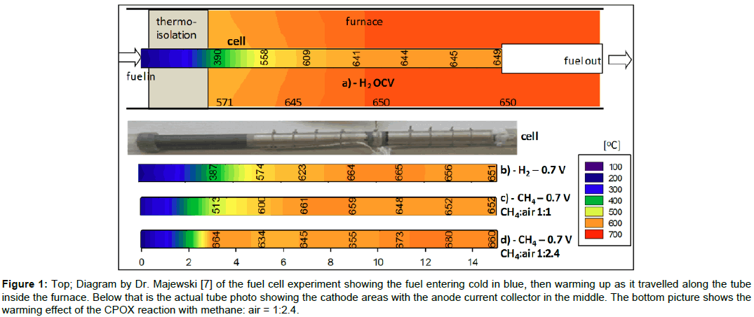
The SOFCs used were 6.6 mm diameter tubes 150 mm long. A photo of a typical tube is shown in Figure 1, illustrating the 50 mm cold inlet upstream length with rubber tube attached, followed by the 95 mm electrode with central anode connection. Silver wire interconnects were used to form a series stack of 16 such tubes in the reactor, with fuel/air mixture manifolded into each tube and preheated cathode air co-flowing along the cells. Each tube was coextruded from 60:40 w:w mixture of NiO:8YSZ forming the 0.6 mm thick anode support covered by a 0.01 mm film of 8YSZ made from a thermoplastic polymer formulation of equal viscosity. After binder burn-out and sintering at 1,400°C, a 2 micrometer barrier layer of GDC was deposited on the electrolyte, followed by a 0.04 mm layer of LSCF cathode. Porous silver ink was painted on the cathode as current collector.
Figure 1: Top; Diagram by Dr. Majewski [7] of the fuel cell experiment showing the fuel entering cold in blue, then warming up as it travelled along the tube inside the furnace. Below that is the actual tube photo showing the cathode areas with the anode current collector in the middle. The bottom picture shows the warming effect of the CPOX reaction with methane: air = 1:2.4.
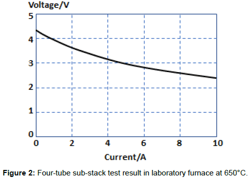
Four such tubular cells were assembled into a sub-stack, and four substacks were used to produce the 16-tube reactor delivering 100W at 11V. When a 4-tube sub-stack was tested in a standard furnace arrangement with hydrogen fuel and air as the oxidant, the results shown in Figure 2 were obtained for a test temperature of 650°C and hydrogen flow rate of 600mlmin-1 [6]. The open circuit voltage was 4.3V, indicating no leaks across the electrolyte and power at 2.8V was 0.2W cm-2 of electrode area. Peak power rose to 0.3 Wcm-2 and total output power for the substack was then 24W for total electrode area of 80 cm2.
The objective was then to improve the system power to weight performance by three methods:-
• Integrate the reforming catalyst in each cell tube
• Integrate the cathode air preheater into the reactor structure
• Use nanoparticle thermal insulation of lower weight
Results and Discussion
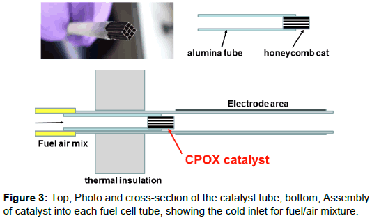
The first experiment was to integrate the reforming catalyst inside each tube as shown in Figure 3, removing the need for a separate reforming reactor which could weigh 1 kg. A 10 mm long piece of aluminosilicate honeycomb catalyst support was carved from a large block and cemented into an alumina tube which could then be sealed into the fuel cell tube at the fuel inlet end. This upstream 50 mm length of the fuel cell tube was used as the cold-sealed entry for the fuel/air inlet which was connected by a silicone rubber tube. Nanoparticle silica insulation 20 mm thick was most effective and was used to support the 16 fuel cell tubes, with the catalyst just in the hot zone to provide Catalytic Partial OXidation (CPOX) of methane mixed with 2.4 parts of air.
The lower diagram of Figure 3 shows how the cool inlet fuel/air mix entered the alumina tube holding the catalyst, then passed through the 20 mm thermal insulation into the hot zone. If the catalyst honeycomb was higher than 450°C, the CPOX (Catalytic Partial OXidation) reaction began to occur and the fuel was converted into hydrogen and carbon monoxide which could then react on the nickel cermet anode. Methane could not be allowed to contact the nickel/YSZ anode tube directly because it caused cracking and coking. The catalyst used in the experiments was precious metal from Johnson Matthey, with proprietary composition. But other catalyst formulations were also tested, including ruthenium nanoparticles which gave good results.
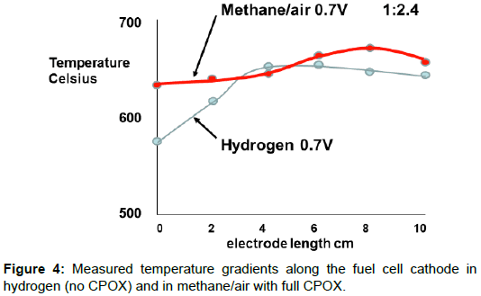
The interesting result was that the CPOX reaction produced an exothermic heating of the inlet gases and this influenced the temperature gradient along the fuel cell electrodes. Figure 1 shows the measurements obtained by inserting a thermocouple down the tube [7]. The blue color on the top left diagram, by Dr Majewski, shows the fuel/ air mix going through the insulation into the hot zone of the furnace which was controlled at 650°C. The cool gas took time to warm up and reached about 500°C at the start of the cathode electrode. Therefore, the first 30 mm of the fuel cell could not produce power because it was too cool. Running the fuel cell on hydrogen at 0.7V produced heat which improved the cathode temperature to 570°C, but there was no CPOX reaction in this case to provide an exotherm.
The bottom picture in Figure 1 shows the effect of the CPOX exotherm when the methane fuel/air mix was 1/2.4, the ideal CPOX ratio for hydrogen and carbon monoxide production, and the cell was producing power at 0.7V. The inlet gas mix was hotter than before, and the cathode electrode had a lower gradient of temperature. The difference produced by the CPOX reaction is plotted in Figure 4, demonstrating how much flatter the fuel cell temperature distribution was, leading to more uniform power production along the electrode length. This method of integrating the fuel processing in each mSOFC tube was first proposed in 1994 [8].
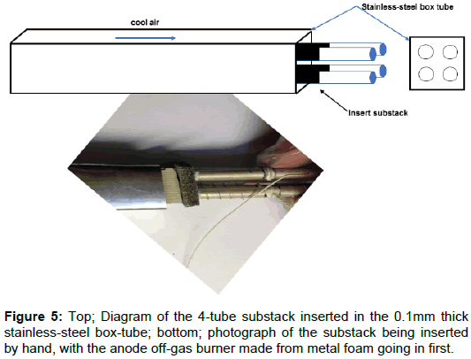
The second experiment was to integrate the cathode air preheater into the reactor, heating the incoming air to 600°C before it meets the electrodes in the fuel cell stack. A typical zig-zag stainless steel plate heat exchanger can weigh 1 kg for a 100W system. By designing a thin stainless-steel box tube for each 4-tube substack, as shown in Figure 5, a stackable light weight air heater was produced, weighing only 100 g and integrated into the compact design. The four sub-stacks could be readily inserted in their box-tubes as shown in the photograph of Figure 5 to give a simple economic solution [9]. Each fuel cell tube had 95 mm of electrode length, while the box-tube heat exchanger was three times longer at 300 mm to give an exhaust gas temperature about 250°C. The volume of the system was bigger than necessary because of wasted space which was filled with insulating material but could be improved by more sophisticated redesign of the heat exchange channels, further reducing system weight.
The third improvement was to use nanoparticle thermal insulation with improved K value of 0.02W/mK. A typical portable SOFC can contain 1 kg of thermal insulating ceramic material to contain the redhot operating temperatures. Using Morgan 20 mm thick WDS Ultra material with 0.2 mm mica covering on both major faces allowed the insulation mass to be reduced to 150 g, while maintaining outer surface temperatures of 50°C.
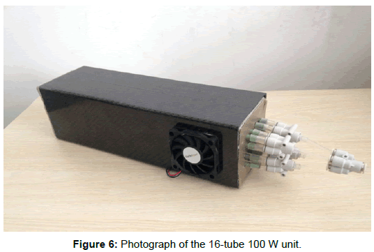
The final design of the mSOFC power supply is shown in Figure 6. The outer case was made from carbon fibre reinforced plastic to give light weight and good mechanical strength. Two fans provided cathode and cooling air to maintain the cells at 650°C in the center of the fuel cell reactor, where a thermocouple was positioned. The 16 tubes with cold inlet can be seen on the right protruding from the 20 mm thick nano-insulation, connected to the plastic manifold supplying the fuel/ air mixture. The electronic control board, fuel valve and CPOX air pump are not shown
The total mass of the unit was 1 kg including fuel, much less than the 10 kg required for a DMFC unit of equivalent power output (P/W = 5Wkg-1) These figures compare to the power to weight ratio of 7Wkg-1 for the Aisin Seiki SOFC generators now installed in 10,000 Japanese homes.
Essentially, this 100W mSOFC design was the same as that tested in the SAFARI project [7] studying LNG truck auxiliary power described in 2015 [10] and the battery charger used in the camper-van project SAPIENS reported in 2017 [11] The reason is that all these applications use 1kWh lead acid batteries in mobile applications which benefit from range extension.
Conclusions
The improvement of power to weight (P/W) ratio for a microtubular 100W SOFC system has been shown experimentally. The first improvement was a CPOX catalyst in each fuel cell tube to obviate the need for a reformer unit. The second was a lightweight recuperator to heat the incoming cathode air. The third was improved nanoparticle thermal insulation. The final system design had a power to weight ratio near 100Wkg-1 and was sufficient to fly a small robot aircraft. Further improvement could be achieved by use of smaller diameter mSOFC tubes.
Acknowledgment
Thanks are due to the SAFARI partners Almus, University of Birmingham, IREC and ZUT, and Mr Johnson Liu of Sinorobot who supported the project.
References
- Greenman J, Holland O, Kelly I, Kendall K, McFarland D, et al. (2003) Towards robot autonomy in the natural world: a robot in predator's clothing. Mechatronics 13: 195-228.
- Kendall K, Howroyd S, Meadowcroft A, Kendall M (2013) Testing Microtubular SOFCs in Unmanned Air Vehicles (UAVs). ECS Trans 57: 451-457.
- Westrich T (2014) Solid Oxide Fuel Cells for man transportable unmanned vehicles.
- Kendall K, Kendall M (2015) High-temperature solid oxide fuel cells for the 21st century: fundamentals, design and applications.
- Torrell M, Morata A, Kayser P, Kendall M, Kendall K, et al. (2015) Performance and long term degradation of 7W micro-tubular solid oxide fuel cells for portable applications. J Power Sources 285: 439-448.
- Kendall K, Prica M (1994) 1st European SOFC Forum. Luzern, Switzerland.
- Kendall K, Newton J, Kendall M (2015) Microtubular SOFC (mSOFC) system in truck APU application. ECS Transactions 68: 187-192.
Citation: Kendall K, Liang B, Kendall M (2018) Mobile Robots Enhanced by microtubular Solid Oxide Fuel Cells (mSOFCs). Innov Ener Res 7:200. DOI: 10.4172/2576-1463.1000200
Copyright: © 2018 Kendall K, et al. This is an open-access article distributed under the terms of the Creative Commons Attribution License, which permits unrestricted use, distribution, and reproduction in any medium, provided the original author and source are credited.
Share This Article
Recommended Journals
Open Access Journals
Article Tools
Article Usage
- Total views: 4022
- [From(publication date): 0-2018 - Feb 22, 2025]
- Breakdown by view type
- HTML page views: 3314
- PDF downloads: 708

