Review Article Open Access
Micro and Nano Fabrication by Powder Metallurgy
Angelo PC*
PSG College of Technology, Coimbatore, India
- *Corresponding Author:
- Angelo PC
PSG College of Technology
Coimbatore, India
E-mail: angelopsg@gmail.com
Received Date: March 25, 2015 Accepted Date: April 27, 2015 Published Date: May 04, 2015
Citation: Angelo PC (2015) Micro and Nano Fabrication by Powder Metallurgy. J Powder Metall Min 4:129. doi:10.4172/2168-9806.1000129
Copyright: © 2015 Angelo PC. This is an open-access article distributed under the terms of the Creative Commons Attribution License, which permits unrestricted use, distribution, and reproduction in any medium, provided the original author and source are credited.
Visit for more related articles at Journal of Powder Metallurgy & Mining
Abstract
Powder Metallurgy (P/M) is recognized today as one of the most important near net shape fabrication techniques for manufacturing several industrial products. Recent advances in aerospace, automotive, bio-engineering, communications, computers and medical fields call for miniaturized components of complex shapes in metals and plastics due to the increasing demands for precision engineered components and systems. P/M process is well suited for manufacturing small and tiny components in large numbers especially by Powder Injection Moulding, an off-shoot of plastic injection moulding. In addition, other fabrication techniques such as, Micro powder injection moulding (μ PIM), Semisolid Powder Processing(SPP), Low pressure injection moulding (LPIM), Nano powder injection moulding (NPIM), Rapid Prototyping(RPT), Micro sacrificial plastic mould insert PIM (μ-SPiPIM), Copowder injection moulding (2C-PIM), Selective Laser Sintering(SLS), Selective Laser Melting(SLM), Laser Micro Sintering(LMS), Electron Beam Melting(EBM) and Nano Forging by FIB/SEM have been adopted to fabricate micro and nano sized components. This paper will discuss the above processes explaining the principle, the equipment used along with specific examples.
Keywords
Powder Metallurgy; Fabrication; Moulding
Introduction
Powder Metallurgy (P/M) is recognized today as one of the most important near net shape fabrication techniques for manufacturing several industrial products [1]. Recent advances in aerospace, automotive, bio-engineering, communications, computers and medical fields call for miniaturized components of complex shapes in metals and plastics due to the increasing demands for precision engineered components and systems. P/M process is well suited for manufacturing small and tiny components in large numbers especially by Powder Injection Moulding [2], an off-shoot of plastic injection moulding. In addition, other fabrication techniques such as Micro powder injection moulding (μ PIM) [3], Semisolid Powder Processing [4], Low pressure injection moulding (LPIM) [5], Nano powder injection moulding (NPIM) [6], Rapid Proto Typing (RPT) [7], Micro sacrificial plastic mould insert PIM (μ-SPiPIM) [8], Co-powder injection moulding (2C-PIM) [9], Selective Laser Sintering (SLS) [10], Selective Laser Melting (SLM) [11], Laser Micro Sintering (LMS) [12], Electron Beam Melting (EBM) [13] and Nano Forging by FIB/SEM [14] have been adopted to fabricate micro and nano sized components. This paper will discuss the above processes explaining the principle, the equipment used along with specific examples.
Powder Injection Moulding
The different steps involved in Powder Injection Moulding (PIM), also known as Metal Injection Moulding (MIM) are shown in Figure 1. PIM-involves mixing of powders of the required alloy with a binder material and lubricant in the form of pellets and injection moulded in a die to form the ‘green’ part. The green part is heated in an oven for debinding. Debinding causes the binder to come out in the form of a liquid or vapour or a combination of both. Removal of the binder can also be carried using water or oxalic acid depending on the binder material employed. After debinding the part is sintered at a suitable temperature so as to bond the powder particles by diffusion into a dense near-net shaped component. Figure 1a shows some of the parts made by PIM.

Figure 1a: Steps in Powder Injection Moulding.

Figure 1b: Parts prepared by PIM.
Main advantages of PIM compared to investment casting or machining are the following:
Higher complexity of geometrical shapes of products, high production rate, high and uniform density, repeatable higher tolerances, applicable to wide range of materials and more importantly minimal scrap loss. There are a few disadvantages such as, high cost of powder, high cost of equipment and high running cost [15].
Micro Powder Injection Moulding
Among the micro-manufacturing technologies, Micro Powder Injection Moulding (μPIM) [3] is capable of manufacturing metallic and ceramic micro-components and systems of complex shapes with very good dimensional accuracy combined with high volume capability. μPIM is an extension and miniaturized version of PIM and uses very fine metal powders of particle size ranging from 2 to 5 microns. Unlike in the conventional PIM, μPIM requires mixing of metal powders with a considerable amount of polymeric binder which is subsequently removed after injection moulding by debinding. Figure 2a shows the equipment used for μPIM. The process steps involved are as follows [16]:
• Clamping-to hold together two halves of the mould
• Injection-to force the feed stock into the mould
• Dwelling-pause in the injection process to fill the mould cavities
• Cooling-to allow solidification within the mould
• Mould opening-to separate the two halves
• Ejecting-to release the finished part from the mould

Figure 2a: Process Steps for Micro PIM.

Figure 2b: Components made by Micro PIM.
Figure 2b shows human ear-bone replacement part weighing 5.4 mg in titanium successfully produced by micro PIM. Typical tolerances possible by micro PIM range between +/- 0.2% and +/- 0.5% of nominal dimensions. The minimum feature dimensions are in the order of ten times the mean particle size and hence finer powders are generally used in micro-fabrication. Figure 3 shows a comparison of parts fabricated by conventional MIM and micro PIM. Table 1 shows the minimum dimensions and maximum aspect ratios of components fabricated by micro PIM using different metallic powders and it can be seen that a wide range of dimensions and aspect ratios have been successfully fabricated by micro PIM using different metal powders.
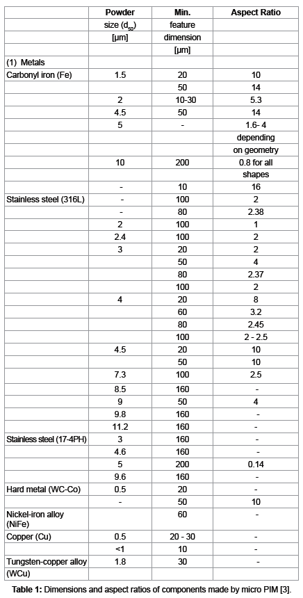

Figure 3: Dimensional tolerance versus size of MIM Products.
Japanese researchers have designed a modified compacting press for forming micro parts by using flow moulding that makes use of the plasticity of the binder inside a heated die [17].
Figure 4 shows the modified compacting press and the micro gear fabricated using the press. The press is so designed that the fluid compounds move only a minimum distance so that the loss of pressure is minimized. The press can also produce two-stepped gears with complex axis.

Figure 4: a) Powder filling. b) Compaction. c) Finished Part.
Effect of Powder Size
Since powder size has a significant effect on part quality, attempts have been made to use nano-sized powders with narrow particle size distribution, for fabricating micro parts. Use of nano- sized particles allow finer structural details to be produced and also result in better surface finish along with fairly isotropic behaviour. However the use of fine powders lead to the following difficulties in moulding due to increase in:
• Feed stock viscosity
• Reactivity of powders (For example, titanium powders)
• Sintering stresses causing distortion in the final part
• Particle agglomeration resulting in difficulties to get high packing density
Studies are being carried out to solve the above difficulties. One solution suggested involves the possibility of using hybrid micro/nano powders. Another area of present study is to produce moulds or dies with correct dimensions and surface quality.
Fabrication of Moulds for Micro PIM
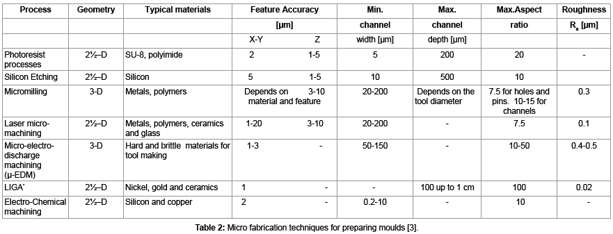
For fabricating micro parts with powders, not only powders are to be produced in the suitable particle sizes to reproduce the moulds they are formed into, it is also necessary to prepare moulds of the correct dimensions and surface quality. Thus the selection of the process for producing the mould is also very important. The basic information regarding the available techniques for preparing moulds for micro fabrication is listed in Table 2.
Among the techniques given in Table 2, micro-milling or micro- EDM is used to fabricate moulds required for preparing parts of complex geometries. For preparing micro-precision components, moulds are prepared either by LIGA or etching techniques or by micro laser ablation.
Micro PIM has also been successfully used to produce tools made from steel, stainless steel and hard metal (WC-Co) [17]. Tools have been made with hard metal with different size holes for producing cylinders, bars of varying widths as well as with different structures of minimum size of 20 microns (Figure 5). Another tool made of hard metal for fabricating gear structures with diameter ranging from 200 to 1500 microns with a depth of 120 microns is shown in Figure 5a.

Figure 5a: Tool made of hard metal.

Figure 5b: Tool for making gears.
Semi Solid Powder Processing (SSPP)
Semisolid powder processing is another promising technique for near net shape micro scale part fabrication. By combining the process of forming in the semisolid state and conventional powder metallurgy, SSPP provides an alternate process for micro fabrication. By replacing bulk materials by powdered materials SSPP enables the tailoring of material properties. It has been shown that metallic powders in the semisolid state can be successfully used to fabricate a two layer functionally graded structure with one layer of aluminium-siliconcopper alloy and the other layer being SiC particles reinforced alloy. Figure 6 shows a schematic of semisolid powder processing set up [3].

Figure 6a: Semisolid Powder Processing.

Figure 6b: Specimens processed by SPP.
Low-pressure injection molding (LPIM)
Low-pressure injection molding (LPIM) is a less-common variant of PIM which due to lower equipment and tooling costs allows fast manufacturing of functional models and therefore is an attractive alternative in the field of product development or smaller production numbers. For the fabrication of micro parts with overall dimensions less than 100 μm with micro details in the range of few microns LPIM can be applied. For further size reduction it is necessary to use powders in the nano scale. Beside miniaturization, there are attractive features such as improved mechanical properties, reduced surface roughness, and lower sintering temperatures with nano scaled powders. However, an increased tendency of nano powders for agglomeration has to be kept in mind (Figure 7). The fabrication of components via LPIM makes use of pressures in the range of 0.1-1 MPa allowing even soft molds from silicone rubber to be used [5].

Figure 7: Specimens prepared byLPIM5.
Nano Powder Injection Moulding (NPIM)
2D and 3D structures with a height-to-width ratio of up to 10 have been recently fabricated using nano powders and a nano powder moulding process. The first step is to fabricate the mould for which a planar substrate made of glass quartz or silicon is used. The mould is filled with slurry of nano metal powder particles. Experiments have been carried out successfully with gold nano particles of 100-700 nm and platinum nano particles of 300-1000 nm. The mould is heated to fuse the particles. Sintering was carried out at 900oC for gold and at 1200oC for platinum at a heating rate of 2 to 3oC per minute for 30 minutes. As a last step, a thin layer of flexible substrate material such as freshly prepared PDMS liquid is deposited on the mould surface. This nano powder moulding process is capable of fabricating nano parts for various applications [6].
Rapid Prototyping (RPT)
Rapid Prototyping (RPT) can be defined as a group of techniques used to fabricate a scale model of a part or assembly using threedimensional computer aided design (CAD) data. What is commonly considered to be the first RPT technique, ‘Stereolithography’, was developed by 3D Systems of Valencia, CA, USA, a company was founded in 1986. Since then, a number of different RPT techniques have become available. RPT models can be used for testing; for preparing an airfoil shape to be tested in a wind tunnel; to create male models for tooling; in some cases, the RPT part can be the final part. RTP can prepare highly convoluted shapes (including parts nested within parts). Rapid Prototyping decreases development time by allowing corrections to a product to be made early in the design process and improves product development by enabling better communication in a concurrent engineering environment [7]. The basic steps for all current rapid prototyping techniques are:
• A CAD model of the required specimen is constructed and converted to STL format.
• The RPT unit processes the STL file by creating sliced layers of the model.
• The first layer of the physical model is prepared by melting a layer of metal powder by laser. The model is lowered to prepare the second layer of powder which is melted by laser and this process is repeated until the model is finished.
• The finished model is removed from the unit and cleaned Figure 8a and 8b.

Figure 8a: Commercial Model for Rapid Prototyping.

Figure 8b: A nested specimen by RPT.
Micro Sacrificial Plastic Mould insert MIM (μ-SPiMIM)
In the micro sacrificial plastic mould insert (μ-SPiMIM) process, a feedstock consisting of the selected metal or alloy powder and a polyacetal-based binder is injected to fill a polymethacrylate mould prepared by the imprint process as shown in Figure 9, after debinding and sintering the part can be used to produce further imprinted sheet allowing mass production of parts [8].

Figure 9: Schematic of Micro Sacrificial Plastic Mould Insert Process.
Micro Two-Component Powder Injection Moulding (2C-MicroPIM)
For the production of highly integrated devices Micro-Two Component Powder Injection Moulding (2C-MicroPIM) is used. The process is suitable for examples like gear/hub components of usually not compatible oxide ceramics (Figure 10a). A well-defined combination of powder and feedstock is a prerequisite for successful process set-up.

Figure 10a: Micro gear wheel (ZrO2)/ shaft (Al2O3)9.
The combination of one or more molten materials in one tool to produce multi-components parts is receiving increasing attention in recent years and Figure 10b shows an example of a combination of magnetic and non-magnetic halves in a single part. Further improvements in the form of fabrication of either two-component or an assembly of parts by micro injection moulding of micro-parts from ceramics, metals, or polymers are expected in the coming years [9].

Figure 10b: Combination of magnetic and non-magnetic halves.
Micro Fabrication by Selective Laser Sintering (SLS)
Selective Laser Sintering (SLS) was developed at the University of Texas in Austin, by Carl Deckard and colleagues. The technology was patented in 1989 and was originally sold by DTM Corporation. DTM was acquired by 3D Systems in 2001. Developed originally in 1987 at the University of Texas to fabricate plastic prototypes, Selective Laser Sintering (SLS), has been adopted for producing parts in a layerby- layer method by laser sintering of metal powders so as to make directly metal parts. In SLS process, fine powder of the selected metal or alloy is spread on the substrate using a roller. Before starting CO2 laser scanning for sintering of a slice the temperature of the entire bed is raised just below its melting point by infrared heating in order to minimize thermal distortion (curling) and facilitate fusion to the previous layer. The laser is modulated in such a way that only those grains, which are in direct contact with the beam, are affected (Pham and Demov, 2001). Once laser scanning cures a slice, bed is lowered and powder feed chamber is raised so that another layer of powder can be spread evenly over the built area by a counter rotating roller. In this process support structures are not required as the unsintered powders act as support structure. It is cleaned away and can be recycled once the model is complete.
In order to fabricate micro metal parts with SLS, the focused laser beam must be very fine and the powder particles must also be fine. Nd Yag laser doubling frequency is used to obtain a fine laser beam of 15 micron diameter. The laser beam is positioned accurately on the surface of the metal powder particles of diameter less than one micron. After melting one layer of metal powder, another layer of metal powder is spread above the melted layer and the process is repeated until the part is fabricated as dictated by a computer‘s CAD program. Laser and/or the deposition surface moves on multiple axes as the part is built layerby- layer. Figure 11a and 11b shows a typical selective laser sintering set up. Parts with 0.1 mm wall thickness and 2 mm height have been successfully fabricated using iron powder particles of 1 to 2 micron size. SLS has proved to be very useful for industries such as aerospace requiring a few specimens as prototypes before freezing the design. SLS being able to store the design digitally eliminates the necessity to produce expensive physical moulds and storing them [10].

Figure 11a: Selective laser sintering set up.

Figure 11b: Typical parts made by SLS.
Selective Laser Melting (SLM)
Selective laser melting started in 1995 at the Fraunhofer Institute ILT in Aachen, Germany and is yet another additive manufacturing process that uses 3D CAD data as a digital information source and energy in the form of a high-power laser beam, to create three-dimensional metal parts. In this process a high power laser beam selectively melts and fuses powdered material spread on a layer. The powder is supplied in precise amounts and is spread by a counter-rotating roller on the table. The table is lowered through a distance corresponding to the layer thickness (usually 0.01 mm) before the roller spreads the next layer of powder on the previously built layer. The unsintered powder serves as the support for overhanging portions, if any in the subsequent layers. The types of materials that can be processed include stainless steel, tool steel, cobalt, chrome, titanium and aluminium. All must exist in atomized form. The types of applications most suited for the selective laser melting process are complex geometries and structures with thin walls and hidden voids or channels on the one hand or low lot sizes on the other hand. It is very advantageous for producing hybrid forms where solid and partially formed or lattice type geometries can be produced together to create a single object. Figure 12a shows the equipment used for fabricating parts by selective laser melting and Figure 12b shows typical parts made by selective laser melting [11].

Figure 12a: Selective Laser Melting Set-up11.

Figure 12b: Specimens made by SLM.
Laser Micro Sintering (LMS)
In the year 2002 laser micro sintering, a modification of selective laser sintering, was developed by Laser institute Mittelsachsen to generate metal micro parts. The sintering of the material is accomplished through laser radiation in a pulsed wave regime. Wavelengths of the employed lasers are in the near infrared, in the visible or in the near UV spectral range shown in Figure 13a and 13b. In the case of metal powders, the suitable wavelength range for laser micro sintering has been the near infrared (NIR) region. Nd: YAG lasers yield the optimum parameters of short and intensive laser pulses suitable for LMS [12].

Figure 13a: Schematic Laser Micro Sintering.

Figure 13b: Specimens made by LMS.
Electron Beam Melting (EBM)
Electron Beam Melting (EBM) is a new alternative for both rapid manufacturing and prototyping metal components. This technology is fast gaining attention for its ability to deliver fully dense parts with properties equal to wrought materials. EBM is capable of producing unprecedented strength-to-weight and buy-to-fly ratios, reducing the cost of raw materials and the weight of the component while opening the door to new design configurations. EBM technology stands out for its ability to produce titanium parts in hours versus days. For industries like aerospace, this technology is used to making proto types g and lowvolume production of components. EBM uses an electron beam to melt powder. After melting and solidifying one layer of powder, the process is repeated until the part as per the CAD programme is fabricated. Figure 14a shows the schematic of Electron beam melting and Figure 14b is a part made by EBM [13].

Figure 14a: Schematic of Electron Beam Melting.

Figure 14b: Ti part made by EBM for Bio-medical Application.
Nanoforging by Scanning Electron Microscope
Availability of nano powders and scanning electron microscope with focused ion beam (FIB/SEM) has led to fabrication of three dimensional nano components. Nano forging can also be carried out using suitable micron or nano size powders. For this process metallic alloys are converted into large number of nano particles. A selected nano particle is kept inside the scanning electron microscope and placed on a micro anvil or die. With the help of a micro hammer the particle is forged to take the shape of the die so as to form a nano sized component [14].
Rosler and his coworkers at the Technical University Braunshweig in Germany have used nickel based superalloys containing Ni3Al type intermetallic precipitates as nano-objects. The precipitates were isolated from the alloy by selective dissolving of the matrix phase so as to Ni3Al particles of edge length 300-500 microns. Placing the particles inside a SEM, a single particle was selected. Using specially designed micro-manipulators the selected particle was placed on an anvil to carry out the forging using specially designed micro-hammer. Figure 15a shows the sequence of the forging operation. Illustration of the nano forging process (Figure 15b):

Figure 15a: Sequence of the forging operation.

Figure 15b: Micro manipulators for nano forging.
(a) The manipulator tip approaches a powder sample of extracted nanoparticles.
(b) The manipulator is isolating and picking up a nano particle.
(c)) The nano-object is being placed on a Si cantilever beam, serving as a micro-anvil
(d) The nano-object is deformed by a tungsten micro hammer on the anvil sequence of the forging operation.
Conclusion
The possibility of micro and nano fabrication using powders has been demonstrated by a variety of manufacturing processes. Micro powder injection moulding has developed into a high volume micro fabrication process for manufacturing metal and ceramic micro components. Semisolid powder processing, Low pressure injection moulding (LPIM), Nano powder injection moulding (NPIM), Micro sacrificial plastic mould insert PIM (μ-SPiPIM), Co-powder injection moulding, (2C-PIM), Selective Laser Sintering, Selective Laser Melting, Laser Micro Sintering, Electron Beam Melting and Nano Forging by FIB/SEM are alternative micro fabrication routes. The μ-SPiMIM process has a great potential to produce complex metallic parts with fine micro-structures. According to the PIM process road map shown in Figure 16 the process is becoming considerably accurate from microscale to nano-scale compared to other micro fabrication techniques. It has demonstrated that micro PIM is favored where the properties of polymers do not satisfy the requirements as in high temperature applications. Micro PIM is also an option for medical applications where bio-compatibility is essential. PIM as an integral part of Additive manufacturing is opening up possibilities for low-cost manufacturing of components and systems not possible by the current technologies. Continued development of machines for full manufacturing readiness and studies to understand the underlying materials processes are essential.

Figure 16: MIM process inroad map on micro-nano processing.
References
- Angelo PC, Subramanian R (2008) Powder Metallurgy: Science,Technology and Applications. Prentice Hall of India Pvt Ltd, New Delhi.
- Baril E, Thomas Y, FHétu J, Pelletier S, Boisclair M, et al. (2006) Powder Injection Molding (PIM) for Low Cost Manufacturing of Intricate Parts to Net-Shape. Cost Effective Manufacture via Net-Shape Processing, Meeting Proceedings RTO-MP-AVT-139.
- Attia UM, Alcock JR (2011) A review of micro-powder injection moulding as a micro fabrication technique. Journal of Micromechanics and Micro engineering.
- Yufeng W (2009) Development of Novel Semisolid Powder Processing for Micro manufacturing. Paper 10568, Doctoral Dissertation,Iowa State University.
- Müller M, Bauer W, Kleissl HJR Low-Pressure Injection Molding of Ceramic Micro Devices Using Sub-Micron and Nano Scaled Powders. Elsvier Ltd, Multi-material Micro Manufacture.
- Rajabi J, Muhamad N, Sulong AB (2012) Effect of nano-sized powders on powder injection molding: A Review.Micro system Technology 18: 1941-1961.
- Kai CC, Fai LK (1998)Rapid Prototyping:Principles and Applications in Manufacturing. World Scientific Publishing Co PteLtd.
- Nishiyabu K, Micro Metal Powder Injection Molding, Japan.
- Dourandish M, Simchi A (2009) Study the sintering behavior of nanocrystalline 3Y-TZP/430L stainless-steel composite layers for co-powder injection molding. J Of MatlSci44: 1264-1274.
- Ping HI, Das S, Wohlert M, Beaman JJ, Bourell DL, et al. (1998) Producing Metal Parts with Selective Laser Sintering. J of Metals 50: 17-20.
- Kruth JP, Froyen L, Vaerenbergh JV, Mercells P, Rombouts M (2004) Selective laser melting of iron-based powder. J of MatlsProc Technology 149: 616-622.
- Regenfuss P, Streek A, Hartwig L, Klötzer S, Brabant TH (2003) Principles of Laser Micro Sintering. Precision Microfabrication:21-24.
- Gong X, Lydon J, Chou K (2015) Characterization of Ti-6Al-4V Powder in Electron Beam Melting Additive Manufacturing.IntJ Powder Met 51: 1-10
- Rosler J, Mukherji D, Schock K, Kleindiek S (2007) Forging of metallic nano-objects for the fabrication of submicron-size components by Nanotechnology.
- Wong KV, Hernandez A (2012) A Review of Additive Manufacturing, International Scholarly Research Network ISRN Mechanical Engineering.
- Imgrund P,Rota A, Kamer L, Kramer S,Kunstaffe(2007) Metal injection moulding at micro scale.International.
- Tsutsui T (1950) Recent Technology of Powder Metallurgy and Applications,Hitachi Powdered Metals Co Ltd.
Relevant Topics
- Additive Manufacturing
- Coal Mining
- Colloid Chemistry
- Composite Materials Fabrication
- Compressive Strength
- Extractive Metallurgy
- Fracture Toughness
- Geological Materials
- Hydrometallurgy
- Industrial Engineering
- Materials Chemistry
- Materials Processing and Manufacturing
- Metal Casting Technology
- Metallic Materials
- Metallurgical Engineering
- Metallurgy
- Mineral Processing
- Nanomaterial
- Resource Extraction
- Rock Mechanics
- Surface Mining
Recommended Journals
Article Tools
Article Usage
- Total views: 20753
- [From(publication date):
August-2015 - Apr 04, 2025] - Breakdown by view type
- HTML page views : 15717
- PDF downloads : 5036