Review Article Open Access
Mechanically Actuated Stance-Control-Orthoses: Advantages, Design Evaluation and Future Directions
| Rakib MI1* and Abu Osman NA2 | |
| 1Manufacturing System Integration, Department of Mechanical Engineering, University of Malaya, Kuala Lumpur, Malaysia | |
| 2Centre of Applied Biomechanics, Department of Biomedical Engineering, University of Malaya, Kuala Lumpur, Malaysia | |
| Corresponding Author : | Muahammad Iftekharul Rakib Graduate Research Assistant, Department of Mechanical Engineering University of Malaya, Kuala Lumpur, Malaysia Tel: 603 7967 6838 Email: muhd.rakib@outlook.com |
| Received: August 24, 2015 Accepted: October 07, 2015 Published: October 09, 2015 | |
| Citation: Rakib MI, Osman NAA (2015) Mechanically Actuated Stance-Control-Orthoses: Advantages, Design Evaluation and Future Directions. J Pain Relief 4:211. doi:10.4172/2167-0846.1000211 | |
| Copyright: © 2015 Rakib MI, et al. This is an open-access article distributed under the terms of the Creative Commons Attribution License, which permits unrestricted use, distribution, and reproduction in any medium, provided the original author and source are credited. | |
| Related article at Pubmed, Scholar Google | |
Visit for more related articles at Journal of Pain & Relief
Abstract
Engineers and researchers have devotedly sought to improve and develop the design of walking assistive devices in last few decades to enhance the mobility of impaired individuals. The progress is quite impressive but a lot of design challenges are still remain in making these designs user-friendly and commercially viable. Patients with weak quadriceps have limited option to walk independently. Knee-ankle-foot orthosis (KAFO) are typically prescribed as walking assistive device. KAFOs keep the knee in full extension to provide knee stability during walking and keep knee straight throughout the gait cycle with mechanical locking system. Locked knee in the swing phase leads to an abnormal gait pattern. Mechanical stance control orthosis (SCO) is designed to release the lock during swing phase to allow free knee motion and lock it again during stance phase with mechanical actuation system. It helps the user to walk more natural way by overcoming the limitations of KAFO. This article discusses the advantages of SCOs over KAFOs, analyses various mechanisms, shows comparison and future directions to overcome design challenges. This article will help the researchers in assistive technology to develop a reliable and user-friendly product for common users with lower cost.
| Keywords |
| Assistive device; Stance control orthosis; Knee ankle foot orthosis; Locking mechanism; Knee collapse; Free knee motion |
| Introduction |
| Many individuals sustain quadriceps weakness or knee instability because of paralysis, spinal cord injury, or polio. They are usually prescribed KAFO, a mechanical device, to assist walking. It provides knee stability and protects knee collapse during standing and the stance phase of gait. KAFO keeps the knee locked in full extension throughout the gait cycle. Hence, knee flexion is prevented during the swing phase. Since KAFO resists free knee motion during swing phase thus individuals have to compensate it by an unnatural gait pattern. This compensatory gait pattern results in the hip hiking of the braced leg during the swing phase to attain sufficient foot-to-ground clearance, circumduction, and contralateral foot vaulting [1,2]. Walking with a locked knee leads to greater metabolic energy expenditure [3]. Traditional KAFOs also limit the ability of users to walk on irregular or inclined surfaces, ascend or descend stairs, and step over obstacles because of inadequate toe clearance. Moreover, long-time use of locked knee KAFO and walking with an abnormal gait may lead to pain and the joint dis-function of the hip and lower back [1]. |
| Rehabilitation researcher could discern the need of a device that would allow knee flexion for obtaining free knee motion during swing phase and provide adequate knee stability for weight bearing during stance phase of gait cycle. Extensive measures were implemented in the last three decades to develop such type of device [4]. Typically these assistive devices are referred as Stance Control Orthosis (SCO). SCOs are designed to lock automatically the knee joint that resists knee flexion during the stance phase and provides sufficient stability to support body weight. The knee actuation mechanism automatically unlocks the knee during the swing phase to allow free knee motion. Therefore, SCO allows more normal gait and greater cosmetic acceptance compared with the traditional fixed-knee KAFO [5]. SCO also improves gait efficiency, kinematics, and mobility. Another significant benefit is the reduction of the metallic energy expenditure of the user [6,7]. |
| Numerous mechanisms and design approaches have been used to develop user friendly mechanically actuated SCO. Because mechanical systems are easy to manufacture and periodic maintenance. Some of these mechanisms and approaches are ratchet or pawl [8], eccentric cam locking system [9], inner pendulum mechanism [10], belt clamping [4], dual stiffness mechanism [11], and hydraulic system [12]. Some of these approaches lack a smooth switching operation between the stance and swing phase, and most are heavy, bulky, and lacking in cosmetic qualities. The purpose of this article is to discuss the advantages of SCOs, analyses various mechanisms, show comparisons and the future directions to overcome design challenges. This article will help the researchers in assistive technology to develop a reliable and user-friendly product for common users with lower cost. |
| Advantages of SCO over Traditional KAFO |
| KAFOs are having a hinge knee joint mechanism that provides knee stability for weight bearing by locking knee joint. But it prevents free knee motion in swing phase that leads to an unnatural gait pattern. Therefore, when a patient ambulates with KAFO and moves his leg forward he has to experience hip hiking in swing phase. In addition redeeming gait pattern comprises foot vaulting, lateral shake or oscillation of upper body and leg motility. Resisting knee flexion during swing phase causes sudden initial loading in stance phase and hinders balanced forward movement of center of mass of the user [13]. According to Waters et al. fixed knee motion can reduce 23-33% of gait efficiency of a patient and elevate center of mass position 65% vertically [7]. Unnatural gait pattern causes soft tissue, hip and knee joint dis-function and motion loss. It leads toward increase in lower limb muscular effort and elevate the energy expenditure during walking [1]. Since, flexed knee actively make shorter the leg in swing phase, thus, free knee motion increases the cadence. It allows the users to walk with more similar to normal gait pattern. Knee flexion is also very essential during stair climbing or slant and ambulation on inclined surface. There is great possibility of stumble with fully extended knee, since, KAFOs resists the leg flex to prevent fall. Hence, the SCO is a solution in this case, because it allows free knee motion during swing phase and resists knee flexion during stance to support weight bearing [13]. In addition some studies recommended free knee motion during swing phase improves walking efficiency and kinematics compare to using KAFO. Irby et al. [14] demonstrated a result of 14 patients using SCO. They had been using it for 6 month in an open enrolment clinical trial. Among those 14 patients seven were novice user and seven were experienced with traditional KAFO. The result exhibited significant enhancement of knee flexion and peak hip flexion for both types of patients. Walking velocity and stride length of novice users were increased substantially. |
| Lehmann et al. [15] investigated the rate of oxygen consumption (OC) and energy cost while using SCO of two spinal cord injury patients and two non-disable subjects. Substantial reduction in energy requirement and OC was observed for two no-disable subject. Since, the two spinal cord injury patients were suffering acute lower limb muscular weakness to flex their leg during swing phase, hence, little improvement was observed for them. Kaufman et al. [16] also investigated the rate of OC for SCO users. His study provided a result for those patients suffered from extremity of lower limb paralysis. The study showed a significant reduction in metabolic energy cost for SCO users and an OC difference of 1 mL/kg/mm between traditional KAFO and SCO users. |
| Zessimopoulos et al. [17] investigated on biomechanical kinematics and energetic effect on non-disable subjects using SCO. The study recommended SCO for the patients of lower limb extremity since it allows users to walk similar with natural gait. It also showed analytical comparisons walking with locked knee mode, free knee motion and stance control mode. Free knee motion and stance control mode showed comparatively similar result with respect to locked knee mode. Study results showed a significant reduction in hip hiking and circumduction during swing phase. The study demonstrated improvement in gait kinematics and enhancement of knee stability during weight bearing. It also revealed the traditional KAFO increases possibilities of stumbling, quadriceps weakness on the affected side and become troublesome during stair ascending and descending. McMillan et al. [1] demonstrated a study on three patients using SCO of Harton Technology Inc. The study reported lower heart rate and improvement in gait kinematics like, increased mobility, faster gait and longer steps. The gait patterns of those subjects were more similar to normal gait as well. |
| Current SCOs Engineering Design Analysis |
| Horton SCO with eccentric cam locking system |
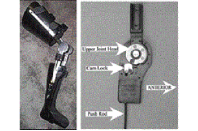
| The Horton SCO is manufactured by Horton Technology, Inc. The device consists of an auto knee-locking system designed with a unidirectional clutch operation [1,9]. The main structural body comprises a thermoplastic ankle-foot orthosis (AFO), two side bars, and a thermoplastic thigh support (Figure 1). A thermoplastic stirrup is attached below the AFO. The basic functional elements of the kneelocking mechanism are a hardened steel eccentric cam and a friction ring. The lock actuation mechanism is governed by the stirrup attached to a push rod. The locking mechanism normally keeps the knee joint unlocked and allows the limb to move freely. The heel strike pushes the stirrup upward at the beginning of the stance phase of the gait cycle, moves the push rod along the length of the side bar, and drives the eccentric cam into the friction ring. The microgrooves on the surface of the eccentric cam and the friction ring prevent slips that could unlock the mechanism. The device remains locked throughout the stance phase and resists knee flexion to provide sufficient stability for weight bearing [9]. The entire assembly is slightly bulky because of the double-locking configuration. |
| Advantages and drawbacks |
| 1. Commercially available product. |
| 2. The orthosis is structurally strong and safe. |
| 3. The entire assembly is a bit bulky because of double-locking mechanism. |
| 4. The stirrup-triggering mechanism can be affected when the user wears shoe. |
| Otto Bock’s Free Walk with Spring Loaded Pawl |
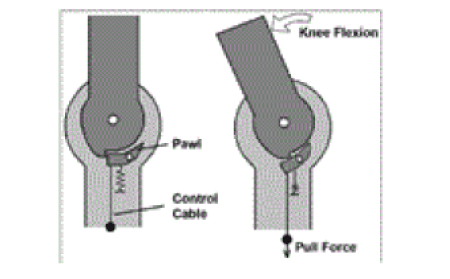
| Otto Bock Free Walk was manufactured by the company Otto Bock and it has similarity in mechanical design and control system with Becker Orthopedic’s UTX [8,18]. The general mechanical design is shown in Figure 2 as a free body diagram. During the beginning of stance phase the knee joint get locked automatically by a spring loaded pawl just before the heel strike. The lock is disengaged by a control cable, which is connected to a pawl. Control cable pulls the pawl downward while the ankle dorsiflexion is 100 and unlocks the knee joint. Disengaging the synchronous knee extension and dorsiflexion of 10° is necessary to eliminate knee flexion movements and to free the ratchet from friction. So here is a possibility of knee to be unsupported during weight bearing with flexed knee [8]. Advantages and drawbacks. |
| This type of SCO is one of the most commercially viable product with a relatively light weight and aesthetic appearance. User friendly because of easy to use and maintenance. Relatively lighter in weight and cosmetic. To engage the knee lock a knee extension moment is required. Hence, it is not suitable when the user is standing relaxed, stumbling or walking on uneven ground, inclines or stairs. The device is not suitable for patients with biomechanical problems that limit dorsiflexion during gait or patients with a fused ankle because 100 dorsiflexion is required to disengage the mechanism. |
| Safety Stride with Internal Lever Engagement System |
| Safety Stride of Becker Orthopaedics is a mechanically controlled and actuated SCO. Its’ knee joint unlocks automatically during the stance phase and allows free knee motion in the swing phase. It is able to restrict knee flexion at any limb angle and does not require any knee extension movement for the switching operation from the stance to swing phase modes. Basically, locking and unlocking operations are governed by control cable. During the late stance phase while maximum ankle dorsiflexion occurs, the control cable pulls the internal lever and unlocks the knee. Before heel strike, the knee extension causes re-engagement of the internal lever with the control cable. The device provides security and stability to patients who sometimes fail to perform full knee extension while walking. A patient with a very weak hip muscle can avail a pneumatic spring at the medial joint which can generate force to assist knee extension before heel strike [19]. |
| Advantages and drawbacks |
| 1. Commercially viable product with a relatively light weight and aesthetic appearance. |
| 2. User friendly because of easy to use and maintenance. |
| 3. Relatively lighter in weight and cosmetic. |
| 4. A pneumatic spring at the medial joint generates force to assist knee extension before heel strike. |
| 5. The device is not suitable for patients with biomechanical problems that limit dorsiflexion during gait. |
| Swing Phase Lock (SPL) with Inner Pendulum Mechanism |
| A gravity-actuated knee-joint locking mechanism prototype, SPL, was designed and developed by Nijenbanning and successfully commercialised by Fillauer LLC. A very simple inner pendulum mechanism was used. It governs the locking and unlocking of knee with respect to the joint angle at sagittal plane. There is a heavier pawl in the mechanism. The pawl can move in or out of the locking position depending on the movement of the object’s thigh angular position. The device is locked in the gait cycle just before heel strike to support the stance. The heavier pawl runs into locking position to lock the knee joint and resists knee flexion. Full extension of the knee is required for proper locking operation because the pawl has to move into the locking position. The device is unlocked during foot off. The pawl is disengaged just before the swing phase, leading to free knee motion [10]. The device can be locked at two positions 00 and 150. Multiple factors, including patient weight, muscle strength, orthotic construction, and knee joint contracture, influence the functioning of the device. |
| Advantages and drawbacks |
| 1. It is a commercially available orthosis. |
| 2. Timing of the device mechanism is compatible enough to be adjusted for preventing any inconsistency of orthosis alignment. |
| 3. The device has four operational modes controlled by a switch. The four modes are: free in motion, automatically unlock or lock, manually lock and manually unlock. A patient can select the automatic lock mode during walking, unlock mode during sitting and lock mode at a standing position. A patient can also select the free in motion mode when driving a car or bicycling [20]. |
| 4. Since a knee extension moment is required for locking operation, it is not suitable for stair climbing and for safely ambulating on a rough ground surface. |
| Belt-clamping Knee Orthotic Joint |
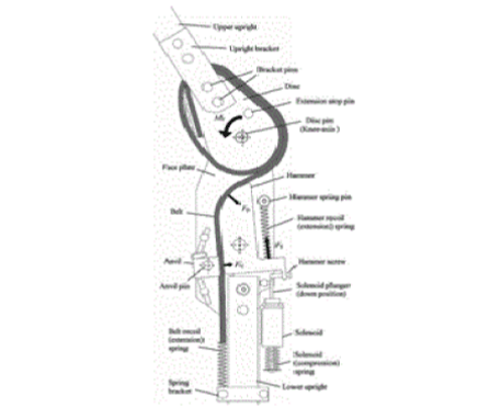
| A novel friction-based belt-clamping mechanism was developed by Yakimovich and retrofitted with a SCO [21]. It permits free knee motion during the swing phase but resists knee flexion at any knee angle during the stance phase to keep the knee in full extension. The knee joint has four primary parts, namely, disc, belt, hammer, and anvil. The disc and face plates, which rotate around the axis of knee rotation, are joined by upper and lower uprights, respectively. A belt is attached between the upper and lower upright of the SCO. The belt wraps the disc to produce friction force, travels over the hammer, and extends up to the belt recoil spring, which can clamp the belt to control its movement (Figure 3). The elastic property of the belt allows slight knee flexion at the beginning of the stance phase to absorb the shock of the heel strike. A push-type solenoid is integrated with the lower upright through a bracket. The main function of the solenoid is to immobilize the hammer. The solenoid plunger is governed by a compression spring. The control system manipulates solenoid action and is connected to a computer. The deactivation of the solenoid allows the hammer movement during stance phase and solenoid activation restricts the hammer movement during swing phase. Several pressure sensors are attached below the footplate of the SCO to sense the stance phase time duration. The signals from these sensors are interpreted with a computer program. During stance phase the pressure sensors sense a pressure that is higher than the pre-set threshold pressure and control system deactivates the solenoid. The disc of the knee joint begins to rotate counter clockwise because of the slight knee flexion moment at the upper upright. The terminal part of the hammer holds the belt tightly with clamping force, thereby restricting the movement of the belt. The disc is therefore unable to rotate further and resists knee flexion. Conversely, during swing phase the control system activate the solenoid as the pressure sensors sense pressure less than the pre-set threshold pressure. The hammer cannot rotate and release the belt form being clamped. Therefore, the belt can travel freely and allows free knee flexion and extension in swing phase. The solenoid becomes deactivated again during the starting of next heel strike. If the control system fails, compression spring pushes the plunger downward to restrict the swing phase mode for ensuring safety [4,21]. |
| Advantages and drawbacks |
| 1. It is not commercially available. |
| 2. Moreover it is a bit bulky. |
| 3. There is a scope of improvement of control system by using a circuit board integrated with SCO and power supply from a rechargeable battery. |
| Dual Stiffness SCKAFO |
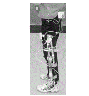
| The SCO developed by Merono et al. [11,22] consists of two identical joints: knee joint and ankle joint. Two different types of actuators was designed and developed for fulfilling the knee and ankle motion. A four bar hinge mechanism was developed (Figure 4) for knee joint. For achieving a motion very similar to knee movement, the rotation of this mechanism was associated by knee movement and displacement with respect to knee axis. The genetic algorithm method by Bayda et al. was used [23]. The algorithm reduced the displacement of SCO caused by the misalignment of the joints. The width of the actuators is 30 mm. During stance phase, the knee joint actuator absorbs shock and help to extend knee fully. During swing phase it helps free knee motion and revert back to knee extension for consequent heel contact. Two different compression springs housed in different cylinders are utilized for the two different phases. The springs are utilized as elastic elements with different levels of stiffness, K1 and K2 for stance and swing control spring respectively, where K1>>K2. An electromagnetic solenoid system was also developed to lock knee joint [22]. At the earlier of stance phase or hill contact, the spring for controlling stance phase is enabled, applies K1 on the orthotic joint and absorbs shock. At the beginning of swing phase, the stance phase spring is disabled and spring for swing control is enabled. The stiffness of spring K2 is enabled for knee extension. The knee joint can move freely during the elastic exchange from K1 to K2. |
| The actuator assembly for the ankle joint has two cylinders. Each cylinder contains a spring and an inner component that is able to move in an inward and outward direction. The two springs in the two different cylinders act independently. These springs are made of smaller discs with a length of 8 mm. These discs can be arranged in different measures to obtain different levels of stiffness. One spring controls plantar flexion, and the other controls dorsiflexion. The spring that controls plantar flexion is activated after the heel strike. The SCO is basically cable driven. A particular amount of dorsiflexion releases the lock through the action of the cable. |
| Advantages and drawbacks |
| 1. Two control systems operate the spring shifting mechanism of the knee actuator. |
| 2. A kinematic measurement unit measures angular velocity of shank and foot. The measurement unit collects data and controls the cable. The cable pulls the spring shifting mechanism in knee actuator and release the knee for free oscillation during dorsiflexion when maximum ankle angle is sensed. |
| 3. Another system is the solenoid-controlled spring shifting mechanism, which collects signals from precision angular displacement measuring sensors attached at the knee, shank, and foot to detect the kinematics of respective parts as input signals and to control the knee actuator [11]. |
| 4. The SCO is bulky and not cosmetic enough for patients. |
| 5. It is not commercially available. |
| Hydraulic Controlled SCO |
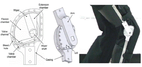
| Yakimovich et al. [12] developed a rotary hydraulic knee orthotic device. The control mechanism of the orthotic device is governed by the angular velocity of the knee joint. The device has a hydraulic rotary piston.The mechanism triggers fluid flow through a unidirectional valve that allows the knee joint engagement when the angular velocity of the knee exceeds a threshold value. The mechanism permits free knee extension when engaged and allows free knee flexion when not engaged. The sensing mechanism of the angular velocity and the control system is fully mechanical and hydraulically activated. The functional components of rotary hydraulic knee orthotic devices are casing, lid, wiper, arm, and valve (Figure 5). The principal structural part is the casing, which is fabricated with 7075-T651 aluminium. The casing also houses a large pocket and a fluid flow channel for valve operation. The fluid flow control valve is unidirectional and spring operated. The wiper is fabricated with 304 stainless steel and serves as a piston inside the pocket. An aluminium lid shrouds the pocket. During knee flexion, the arm rotates in a counter clockwise direction and reduces the volume of flexion chamber inside the pocket. Therefore, the fluid inside the chamber begins to flow through the valve channel and enters the extension chamber. This flowing fluid exerts force on the spring-operated valve. The valve remains open until the fluid force is less than that of the valve spring force. When the knee angular velocity increases, the fluid flow velocity also increases. When the knee angular velocity exceeds the threshold value, the fluid velocity increases to a certain value, thereby causes the fluid flow force to be higher than valve spring force. The unidirectional valve closes and resists the fluid flow. Hence, the orthotic joint is engaged and prevents further knee flexion. |
| Advantages and drawbacks |
| 1. No need of external power source. |
| 2. The device can be easily integrated with standard SCO and has a low noise level. |
| 3. The engaged orthotic knee joint can generate an adequate moment to prevent a 77 kg patient from falling while allowing slow knee flexion. |
| 4. The orthotic knee joint is compact. |
| 5. The joint engagement optimization of time and position can be done by improving the hydraulic system. More optimized calculation of the stiffness of the valve operation spring is necessary. |
| Ottawa Speed |
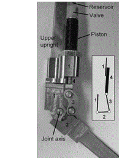
| Ottawa Speed is basically a fluid based device. It was designed for people with knee-extensor weakness and easily can be retrofit with standard KAFO. A slider crank mechanism was designed and developed with a linear piston and a commercially available hydraulic cylinder (threaded mini-cylinders, Vektek Inc; Emporia, Kansas). It also includes (1) upper upright and hydraulic cylinder frame, (2) lower upright crank, (3) connecting-rod link, and (4) piston slider (Figure 6). Upper-upright and hydraulic-cylinder frame is pin-connected to lower-upright crank at knee-joint axis. The linear piston builds up higher fluid pressure while allowing unrestricted fluid flow through an open valve. The cylinder was modified to reduce unused space in order to achieve compactness. An adjustable check valve was attached at the end of the modified cylinder and a fluid reservoir was attached with the valve. The overall device length was less than 17 cm. |
| While the human knee flexes, the piston pushes fluid through a spring operated valve. The fluid flow generates a pull force on the valve. As knee angular velocity increases the piston guided fluid flow rate also increases, therefore, it enhance the pull force on the ball. While the pull force on the ball overcome the spring force, the ball moves into the valve channel and resist fluid flow from the piston to the fluid reservoir. The resulting increase in pressure resists further knee flexion. When the knee extends, pressure is removed and the spring pushes the ball away from the valve channel and allows free knee motion [24,25]. |
| Advantages and drawbacks |
| 1. Overall design is compact and the device weight is 394 gm. |
| 2. Easy to retrofit with standard KAFO. |
| 3. It protects from stumble but allows free knee motion during the swing phase. |
| 4. Lower noise level and cosmetic. |
| 5. Not commercially available yet. |
| Prefabricated SCO Device |
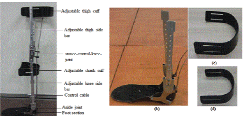
| Rakib et al. developed a user-friendly and light-weight prefabricated SCO device [26,27]. The device is a prefabricated and adjustable SCO (Figure 7a). The device design is modular, compact and light. The thigh and shank support braces are made of carbon-fibre-epoxy composite material. Side bars are made of aluminum-alloy 7075-T6 and the foot section is made of polypropylene. A stance-control-knee-joint (SCKJ) with internal lever engagement mechanism is used in the knee joint of the device. The SCKJ locking and unlocking system is operated by a controlled cable. A double-action-ankle-joint (DAAJ) is used at the ankle joint of the foot part. The DAAJ is also connected with the control cable. The SCKJ remains locked throughout the stance phase. During the end of stance phase, maximum ankle dorsiflexion takes place and causes the control cable to pull the lever and unlocks the SCKJ. SCKJ remains unlocked throughout the swing phase. Before the heel strike, the knee extension causes the lever to reengage the lock of SCKJ. The aluminum-alloy made side bars contain adjustable feature, therefore, the overall height of the device could be easily adjusted by changing the position of the bolts (Figure 7b). Thigh and shank support-braces contain adjustable slots (Figure 7c and 7d). Supportbraces can be attached with the side bars by bolts and easily adjustable by changing the bolts position through the slots. These all adjustable features made it suitable to accommodate patients from 153 cm to 183 cm in height. The overall weight of the device is only 1.1 kg. |
| Advantages and drawbacks |
| 1. The device is prefabricated and all adjustable features made it suitable to accommodate patients from 153 cm to 183 cm in height. |
| 2. The overall design is simple and compact. Moreover, it is light (1.1 kg) [27]. |
| Discussion |
| Findings in SCOs design criteria |
| The prime and basic functions of SCOs are to keep the knee stiff enough by locking the knee joint during stance phase and provide free knee flexion and extension during swing phase. A number of design criteria should be fulfilled to develop a SCO that is competent enough with more beneficial features. |
| 1. For stair climbing or slant and to recover from stumble the device should capable to resist knee flexion and keep it rigid at any knee or ankle angle during stance phase. |
| 2. For permitting the user to seat and stair climbing or slant the device should allow the motion at any knee or ankle angle while it can sense limb unloading. |
| 3. The device should comprise smooth and quick switching system between stance and swing modes. The reaction time should be less than 6 milliseconds. |
| 4. For smooth forward movement of body centre of mass (COM) the design of a device should include controlled knee flexion at stance phase. |
| 5. The device should be noise free. |
| 6. The device should be light and cosmetic in appearance. The overall weight should not be more than 2.5 kg. |
| 7. The device should be less bulky. |
| 8. Design complexity should be eliminated for easy manufacturing and to minimize cost. |
| Future Direction |
| Extensive improvement has been carried out in last few decades to design and develop orthosis competitive for various impaired patient, however, several design challenges remain. An ideal SCO should reluctant from limitations. A number of factors limit current commercial designs. If these limitations can be overcome day by day, the number of users will be increased significantly. The rate of rejection will be minimized as well. A proper design can also enhance the ease of mobility, level of user confidence and security. Better three dimensional human gait model analysis can assist for better realization of musculoskeletal morphology of lower limb locomotion and neural function. That could leads to a low-mass orthotic design [28]. |
| Smooth and quick switching system between stance and swing phase mode is a remarkable challenge till now. Still now many designs comprises control cable operated switching mechanism. Research works on selecting and developing high yield strength material for control cable is necessary. Fluid based actuation system can be a good solution as well. |
| Because, fully extended knee is required for generating knee extension moment to lock the knee joint of some SCOs. Therefore, many SCOs are not suitable for stair climb or slant and prevent stumbling. Pneumatic spring can be a solution for providing automatic knee extension moment. |
| Many SCOs are heavy, complicated in shape and considerably noisy. These are very important design challenges since it can reduce rate of rejection significantly. Additional modification is required to make SCOs more cosmetic, lighter, and noise free. Lighter composite material like carbon fibre plastic can be used for main structural element. Noise can be minimized by avoiding metal to metal contact in design. |
| High stress development inside the devices inner element is also an important issue, since, durability and life time is another important design challenge. During stance phase large amount forces develop into tiny elements having smaller area. Hence, force should be distributed at low concentrations to reduce stress. Material development of higher rigidity to weight can be a solution for this problem. |
| In the future, CAD-CAM process can be employed for designing, developing and manufacturing of SCOs. In such case, human lower limb outer shape can be scanned by a 3D scanner. It will generate a 3D geometric profile and anatomical data of patient’s leg. These geometric and anatomical data could give an accurate design profile of an orthotic device. Hence, after CAD design, the orthoses can be constructed with parallel CAM works. In this case, intimacy of orthotic device and human body part would be good enough to inhibit relative movement between device and human limb. It will also abolish skin sores as well. |
| Conclusion |
| Impaired individuals with lower limb muscle weakness are very often prescribed to use KAFO for supporting the user body weight and assisting to work and stand. Since KAFOs resist free knee motion during swing phase and compel to walk with an abnormal gait pattern the rejection rate is about 58% to 79% [16,29]. SCOs are a good alternative as they are designed to allow free knee motion during the swing phase while providing knee stability for weight bearing during the stance phase. SCOs facilitate ambulation with a more natural gait. However, the success of commercially viable mechanical SCO designs is limited because of the weight, bulkiness, lack of enough cosmetic appeal, noise, and cost. In addition creation of a compact and less bulky design is limited by the high stress formation in the inner elements of the device while supporting the body weight of the user during the stance phase. Design optimization is also be smeared for obtaining a smooth switching between stance phase and swing phase, necessity of external moment before heel strike and efficient manufacturing system. Greater user acceptance and lower rejection rate of a SCO design may be achieved by overcoming these design challenges and functional improvement. |
| Acknowledgment |
| This research is supported by UM High Impact Research Grant (UM.C/HIR/MOHE/ENG/28 and UM.C/HIR/MOHE/ENG/10) from University of Malaya, Malaysia. |
References
- McMillan AG, Kendrick K, Michael JW, Aronson J, Horton GW (2004) Preliminary evidence for effectiveness of a stance control orthosis J Prosthet Orthot 16(1): 6-13.
- Kerrigan DC, Frates EP, Rogan S, Riley PO (2000) Hip hiking and circumduction: quantitative definitions. Am J Phys Med Rehabil 79: 247-252.
- Mattsson E, Broström LA (1990) The increase in energy cost of walking with an immobilized knee or an unstable ankle. Scand J Rehabil Med 22: 51-53.
- Yakimovich T, Kofman J, Lemaire ED (2006) Design and evaluation of a stance-control knee-ankle-foot orthosis knee joint. IEEE Trans Neural Syst Rehabil Eng 14: 361-369.
- Irby SE, Bernhardt KA, Kaufman KR (2005) Gait of stance control orthosis users: the dynamic knee brace system. Prosthet Orthot Int 29: 269-282.
- Irby SE, Kaufman KR, Mathewson JW, Sutherland DH (1999) Automatic control design for a dynamic knee-brace system. IEEE Trans Rehabil Eng 7: 135-139.
- Waters RL, Campbell J, Thomas L, Hugos L, Davis P (1982) Energy costs of walking in lower-extremity plaster casts. J Bone Joint Surg Am 64: 896-899.
- Leederdam NV, Kunst E (1999) New UTX-swing orthosis: Normal gait and safe standing, Orthopadie Technik 50: 506-515.
- Hatton BJ, Hatton DL, Wallace ZG (2003) “Articulating knee supports”, U.S. Patent No. 6,635,024, issued October 21, DC.
- Nijenbanning G, Goudsmit JA (2005) “Gravity operated locking hinge”, U.S. Patent No. 6,979,304, issued December 27.
- Cullell A, Moreno JC, Rocon E, Cordero AF, Pons JL (2009) Biologically based design of an actuator system for a knee-ankle-foot orthosis Mech. Mach. Theory 44: 860-872.
- Lemaire ED, Goudreau L, Yakimovich T, Kofman J (2009) Angular-velocity control approach for stance-control orthoses. IEEE Trans Neural Syst Rehabil Eng 17: 497-503.
- Yakimovich T, Lemaire ED, Kofman J (2009) Engineering design review of stance-control knee-ankle-foot orthoses. J Rehabil Res Dev 46: 257-267.
- Irby SE, Bernhardt KA, Kaufman KR (2007) Gait changes over time in stance control orthosis users. Prosthet Orthot Int 31: 353-361.
- Lehmann JF, Stonebridge JB (1978) Knee lock device for knee ankle orthoses for spinal cord injured patients: an evaluation. Arch Phys Med Rehabil 59: 207-211.
- Kaufman KR, Irby SE, Mathewson JW, Wirta RW, Sutherland DH (1996) Energy-efficient knee-ankle-foot orthosis: A case study J. Prosthet. Orthot 8(3): 79-85.
- Zissimopoulos A, Fatone S, Gard SA (2007) Biomechanical and energetic effects of a stance-control orthotic knee joint. J Rehabil Res Dev 44: 503-513.
- Leerdam NGV (1993) The swinging UTX orthosis, biomedical fundamentals and conceptual design, Disserta-tion for the Doctoral Degree, University of Twente: Enschede, The Netherlands 57-65.
- Tal S, Shelly R (2008) “Knee-ankle-foot orthotic device." U.S. Patent 7,462,159, issued December 9.
- Travolta R (2002) “Stance control revolutionizes knee bracing”, Biomechanics 10: 53-62.
- Yakimovich T, Lemaire ED, Kofman J (2006) Preliminary kinematic evaluation of a new stance-control knee-ankle-foot orthosis. Clin Biomech (Bristol, Avon) 21: 1081-1089.
- Moreno JC, Brunetti F, Rocon E, Pons JL (2008) Immediate effects of a controllable knee ankle foot orthosis for functional compensation of gait in patients with proximal leg weakness. Med Biol Eng Comput 46: 43-53.
- Baydal JM, Barberà R, Belda JM, Poveda R, Durá JV, et al. (2006) Performance validation of an innovative orthotic knee joint based on an optimal four bar linkage J Biomech 39: S72-S72.
- Lemaire ED, Samadi R, Goudreau L, Kofman J (2013) Mechanical and biomechanical analysis of a linear piston design for angular-velocity-based orthotic control. J Rehabil Res Dev 50: 43-52.
- Montgomery W (2013) Development and Application of a Virtual Reality Stumble Method to Test an Angular Velocity Control Orthosis. Doctoral dissertation. University of Ottawa.
- Rakib MI, Choudhury IA, Hussain S, Osman NAA (2015) Design and biomechanical performance analysis of a user-friendly orthotic device. Materials & Design 65: 716-725.
- Rakib MI, Choudhury IA, Osman NAA (2014) Development of a Prefabricated and User Friendly Stance-Control Orthosis. In 2014 3rd International Conference on Environment Energy and Biotechnology 70: 80-83.
- Lobet S, Detrembleur C, Massaad F, Hermans C (2013) Three-dimensional gait analysis can shed new light on walking in patients with haemophilia. ScientificWorldJournal 2013: 284358.
- Bernhardt KA, Irby SE, Kaufman KR (2006) Consumer opinions of a stance control knee orthosis. Prosthet Orthot Int 30: 246-256.
Figures at a glance
 |
 |
 |
 |
| Figure 1 | Figure 2 | Figure 3 | Figure 4 |
 |
 |
 |
| Figure 5 | Figure 6 | Figure 7 |
Relevant Topics
- Acupuncture
- Acute Pain
- Analgesics
- Anesthesia
- Arthroscopy
- Chronic Back Pain
- Chronic Pain
- Hypnosis
- Low Back Pain
- Meditation
- Musculoskeletal pain
- Natural Pain Relievers
- Nociceptive Pain
- Opioid
- Orthopedics
- Pain and Mental Health
- Pain killer drugs
- Pain Mechanisms and Pathophysiology
- Pain Medication
- Pain Medicine
- Pain Relief and Traditional Medicine
- Pain Sensation
- Pain Tolerance
- Post-Operative Pain
- Reaction to Pain
Recommended Journals
Article Tools
Article Usage
- Total views: 13191
- [From(publication date):
November-2015 - Apr 04, 2025] - Breakdown by view type
- HTML page views : 12203
- PDF downloads : 988
