Mechanical Elements of Rectangular Nonprismatic Members for Symmetrical Parabolic Haunches Subjected to a Uniformly Distributed Load
Received: 18-Jun-2013 / Accepted Date: 28-Aug-2013 / Published Date: 30-Aug-2013 DOI: 10.4172/2168-9717.1000111
Abstract
This paper presents mechanical elements of rectangular nonprismatic members for symmetrical parabolic haunches subjected to a uniformly distributed load by through analytical models, these are: fixed-end moments, carry-over factors and stiffness factors. The properties of the rectangular cross section of member vary along its axis “x”, i.e., the width “b” is constant and the height “h” varies along the beam, this variation is parabolic type. Traditional methods for nonprismatic members to obtain the deflections used the Simpson’s rule, or any other technique to perform numerical integration, and the tables showing some authors are restricted to certain relationships. Also a comparison is made between the proposed models and tables that show some authors. Besides the effectiveness and accuracy of the developed models, a significant advantage is that fixed-end moments, carry-over factors and stiffness factors are calculated for any rectangular cross section of the beam using the mathematical formulas.
Keywords: Nonprismatic members; Parabolic haunches; Fixed-end moments; Carry-over factors; Stiffness factors
73983Introduction
One of the major concerns of structural engineering over the past 50 years is to propose elastic methods dependable to satisfactorily model to the variable cross section members, such that it is having certainty in the determination of mechanical elements, strains and displacements that allow properly design this type of members.
During the last century, between 1950 and 1960 were developed several design aids, as those presented by Guldan [1], and the most popular tables published by the Portland Cement Association (PCA) in 1958 “Handbook” [2], where stiffness constants and fixed-end moments of variable section members are presented because the limitations for extensive calculations at that time, in the PCA tables were used several hypotheses to simplify the problem, among the most important pondering the variation of the stiffness (linear or parabolic, according the case of geometry) in function of main moment of inertia in flexure, considering independent cross section, it was demonstrated as incorrect. Furthermore the shear deformations and the ratio of length-height of beam are neglected in the definition of stiffness factors, simplifications can lead to significant errors in determining stiffness factors [3].
Elastic formulation of stiffness for members of variable section was evolved over time, and after the publication of the PCA tables, the following works deserve special mention all based on beams theory: Just [4] was the first to propose a rigorous formulation for members of variable cross section of drawer type and “I” based on the classical theory of beams of Bernoulli-Euler for two-dimensional member without including axial deformations. Schreyer [5] proposed a more rigorous theory of beams for members varying linearly, which the hypothesis generalized by Kirchhoff were introduced to take account the shear deformations. Medwadowski [6] resolved the problem of flexure in beam of shear nonprismatic using the theory of variation calculus. Brown [7] presents a method which uses approximate interpolation functions consistent with beam elastic theory and the principle of virtual work to define the stiffness matrix of members of variable section.
Matrices of elastic stiffness for two-dimensional and threedimensional members of variable section based on classical theory of beam by Euler-Bernoulli and flexibilities method taking into account the axial and shear deformations, and the cross section shape is found in Tena and Zaldo [8] and in the appendix B [9].
In traditional methods used for the variable cross section members, the deflections are obtained by Simpson’s rule or some other technique to perform numerical integration, and tables presenting some books are limited to certain relationships [10-12].
This paper presents mechanical elements of rectangular nonprismatic members for symmetrical parabolic haunches subjected to a uniformly distributed load by through analytical models, these are: fixed-end moments, carry-over factors and stiffness factors. The properties of the rectangular cross section of member vary along its axis “x”, i.e., the width “b” is constant and the height “h” varies along the beam, this variation is parabolic type. Also a comparison is made between the proposed models, and tables that show some authors to see the differences.
Proposed Models
General principles of the parable
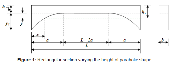
Figure 1 shows a beam in elevation and also presents its rectangular cross-section taking into account the width “b” is constant and height “hx” varying of parabolic shape in three different part.
The value “hx” varies with respect to “x”, this gives:
 (1)
(1)
Now, the properties of the parable are used:
Equation for 0 ≤ x ≤ a:
 (2)
(2)
Equation for a ≤ x ≤ L – a:
 (3)
(3)
Equation for L − a ≤ x ≤ L:
 (4)
(4)
Derivation of the equations for uniformly distributed load
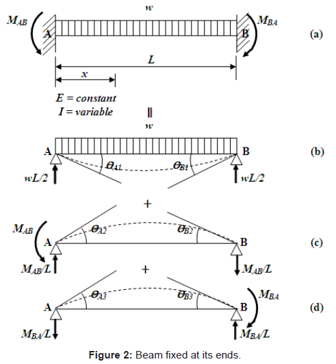
Fixed-end moments: Figure 2a shows the beam “AB” subjected to a uniformly distributed load and fixed-ends. The fixed-end moments are found by the sum of the effects. The moments are considered positive in counterclockwise and the moments are considered negative in clockwise. In Figure 2b shows the same beam simply supported at their ends at the load applied to find the rotations “ΘA1” and “ΘB1”. Now, the rotations “ΘA2” and “ΘB2” are caused by the moment “MAB” applied in the support “A”, according to Figure 2c, and in terms of “ΘA3” and “ΘB3” are caused by the moment “MBA” applied in the support “B”, seen in Figure 2d [13,14].
The conditions of geometry are [13-15]:
 (5)
(5)
 (6)
(6)
The beam of Figure 2b is analyzed to find “ΘA1” and “ΘB1” by Euler-Bernoulli theory to calculate the deflections [16,17].
The equation is:
 (7)
(7)
where: dy/dx=“Θz is the total rotation around the axis “z”, E is the modulus of elasticity of the material, Mz is the moment around the axis “z”, Iz is the moment of inertia around the axis “z”.
The moment at any point of the beam on axis “x” is [18]:
 (8)
(8)
The moment of inertia for a rectangular member is:
 (9)
(9)
Equation (2), (3) and (4) for the three different segments are substituted into Equation (9), it is presented:
Equation for 0 ≤ x ≤ a:
 (10)
(10)
Equation for a ≤ x ≤ L – a:
 (11)
(11)
Equation for L − a ≤ x ≤ L:
 (12)
(12)
Then, the moment of inertia for a member of rectangular section is presented in Equations (10), (11) and (12).
a) For the segment 0 ≤ x ≤ a:
Substituting Equations (8) and (10) into Equation (7) is presented:
 (13)
(13)
Integration of Equation (13) is developed:
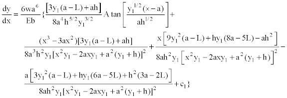 (14)
(14)
Substituting x=a, into Equation (14) to find the rotation dy/dx=ΘA1, where the height “hx” varies the parabolic shape, it is:
 (15)
(15)
b) For the segment a ≤ x ≤ L – a:
Substituting Equations (8) and (11) into Equation (7) is presented:
 (16)
(16)
Integration of Equation (16) is presented:
 (17)
(17)
The boundary conditions are substituted into Equation (17), when x=L/2 and dy/dx=0 by symmetry that occurs, we get C2=L2/12. Then Equation (17) is showed:
 (18)
(18)
Now, the boundary conditions are substituted into Equation (18), when x=a, to find the rotation dy/dx=Θa2, it is:
 (19)
(19)
The boundary conditions are substituted into Equation (18), when x=L − a, to obtain the rotation dy/dx=Θb2, it is:
 (20)
(20)
Then, the Equations (15) and (19) are equalized, because rotations must be equal at the point x=a, where the height “hx” varies parabolically to find the constant “C1”, this is:
 (21)
(21)
Equation (21) is substituted into Equation (14) to obtain the rotations anywhere of the segment 0 ≤ x ≤ a:
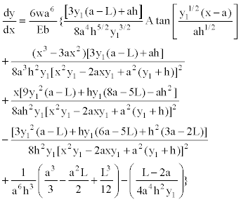 (22)
(22)
Substituting x=0, into Equation (22) to find the rotation in support “A”, it is presented:
 (23)
(23)
c) For the segment L− a ≤ x ≤ L:
Equations (8) and (12) are substituted into Equation (7), it is presented:
 (24)
(24)
Equation (24) shown:
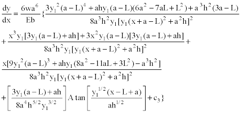 (25)
(25)
Substituting x=L− a, into Equation (25) to find the rotation dy/dx=Θb3, where the height “hx” varies the parabolic shape, it is:
 (26)
(26)
Then, the Equations (20) and (26) are equalized, because rotations must be equal at the point x=L− a, where the height “hx” varies parabolically to find the constant “C3”, this value is:
 (27)
(27)
Equation (27) is substituted into Equation (25) to obtain the rotations anywhere of the segment L− a ≤ x ≤ L:
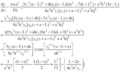 (28)
(28)
Substituting x=L, into Equation (28) to find the rotation in support “B”, it is presented:
 (29)
(29)
Now, the beam of Figure 2c is analyzed to find “ΘA2” and “ΘB2” in function of “MAB” [16,17]:
The moment at any point of the beam on axis “x” is [18]:
 (30)
(30)
Using the same procedure of previous case, we obtained the following results:
 (32)
(32)
 (32)
(32)
Subsequently, the member of Figure 2d is analyzed to find “ΘA3” and “ΘB2” in function of “MBA” [16,17]:
The moment at any point of the beam on axis “x” is [18]:
 (33)
(33)
Using the same procedures of previous cases, we obtained the following results:
 (34)
(34)
 (35)
(35)
Equations (23), (31) and (34) of the support “A” is substituted into Equation (5) and Equations (29), (32) and (35) of the support “B” is substituted into Equation (6), these Equations are developed to find “MAB” and “MBA”, it is as follows:
 (36)
(36)
Then, value of “MAB” and “MBA” are equal, this is a logical situation, since the member is symmetrical.
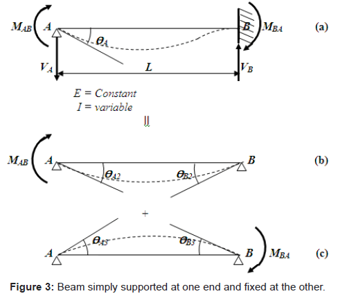
Carry-over factors and stiffness: In order to develop the method to obtain the carry-over factor and stiffness, it will be helpful to consider the following problem: If a clockwise moment of “MAB” is applied at the simple support of a straight member of variable cross section simply supported at one end and fixed at the other, find the rotation “ΘA” at the simple support and the moment “MBA” at the fixed end, as shown in Figure 3.
The additional end moments, “MAB” and “MBA”, should be such as to cause rotations of “ΘA” and “ΘB”, respectively. If “ΘA2” and “ΘB2” are the end rotations caused by “MAB”, according to Figure 3(b), and “ΘA3” and “ΘB3” by “MBA”, these are observed in Figure 3(c).
The conditions of geometry required are [13]:
 (37)
(37)
 (38)
(38)
The beam of Figure 3b is analyzed to find “ΘA2” and “ΘB2” in function of “MAB” are shown in Equations (31) and (32). The beam of Figure 3c is analyzed to find “ΘA3” and “ΘB3” in function of “MBA” of the same way; these were obtained by Equations (34) and (35).
Now, Equation (32) and (35) are substituted into Equation (38). Subsequently, this is used to obtain “MBA” in function of “MAB”:
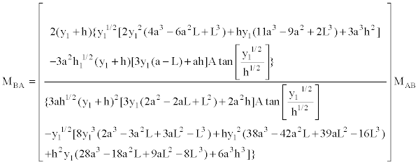 (39)
(39)
Therefore, the carry-over factor of “A” to “B” is the ratio of the moment induced at point “B” due to the moment applied at point “A”; this is the moment coefficient “MAB” expressed in the Equation (39). The carry-over factor of “B” to “A” is equal, since the member is symmetrical.
Now, Equation (31) and (34) are substituted into Equation (37). Subsequently, Equation (39) is substituted in this same Equation to find “MAB” in function of “ΘA”:
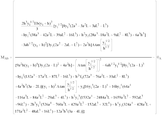 (40)
(40)
Now, if we present the stiffness factor as a function of the moment of inertia, this is shown as follows:
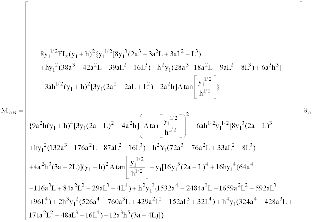 (41)
(41)
Therefore, the stiffness factor is the moment applied at the point “A” due to the rotation induced of 1 radian in the support “A”; this is the coefficient of the rotation “ΘA” expressed in the Equation (40). The stiffness factor of the moment applied at the point “B” due to the rotation induced of 1 radian in the support “B”, also is expressed in the Equation (40), since the member is symmetrical.
Results
Table 1 shows the comparison of the two models, the proposed model is the mathematical model presented in this paper and the traditional model is shown in the table.
| Haunches | Fixed-end moments = mwl2 |
Carry-over factors | Stiffness = kABEI/L |
||||
|---|---|---|---|---|---|---|---|
| m | CAB = CBA | kAB = kBA | |||||
| a | y1/h | PM | TM | PM | TM | PM | TM |
| 0.10 | 0.4 | 0.0873 | 0.5368 | 4.5642 | |||
| 0.6 | 0.0885 | 0.5429 | 4.7594 | ||||
| 1.0 | 0.0902 | 0.5643 | 5.0504 | ||||
| 1.5 | 0.0915 | 0.5772 | 5.3012 | ||||
| 2.0 | 0.0924 | 0.5858 | 5.4798 | ||||
| 0.20 | 0.4 | 0.0903 | 0.5655 | 5.1604 | |||
| 0.6 | 0.0925 | 0.5872 | 5.6311 | ||||
| 1.0 | 0.0955 | 0.0956 | 0.6186 | 0.619 | 6.4123 | 6.41 | |
| 1.5 | 0.0980 | 0.6445 | 7.1711 | ||||
| 2.0 | 0.0996 | 0.6622 | 7.7650 | ||||
| 0.30 | 0.4 | 0.0923 | 0.5854 | 5.7580 | |||
| 0.6 | 0.0952 | 0.6154 | 6.5777 | ||||
| 1.0 | 0.0994 | 0.6601 | 8.0959 | ||||
| 1.5 | 0.1028 | 0.6979 | 9.7831 | ||||
| 2.0 | 0.1050 | 0.7242 | 11.2682 | ||||
| 0.40 | 0.4 | 0.0934 | 0.5965 | 6.3244 | |||
| 0.6 | 0.0968 | 0.6319 | 7.5376 | ||||
| 1.0 | 0.1017 | 0.6860 | 10.0223 | ||||
| 1.5 | 0.1058 | 0.7333 | 13.1794 | ||||
| 2.0 | 0.1085 | 0.7668 | 16.3398 | ||||
| 0.50 | 0.4 | 0.0937 | 0.5991 | 6.8352 | |||
| 0.6 | 0.0972 | 0.6363 | 8.4464 | ||||
| 1.0 | 0.1025 | 0.1025 | 0.6945 | 0.694 | 12.0224 | 12.03 | |
| 1.5 | 0.1069 | 0.7465 | 17.1028 | ||||
| 2.0 | 0.1099 | 0.7840 | 22.8026 | ||||
PM=Proposed model
TM=Traditional model
Table 1: Mechanical elements of rectangular nonprismatic members for symmetrical parabolic haunches subjected to a uniformly distributed load.
According to this table shows that there are only two values for symmetric parabolic haunches and these are equal.
PM=Proposed model
TM=Traditional model
Also other way to validate the proposed model is as follows: in Equations (36) is substituted “a=0L” to obtain the fixed-end moments “MAB=wL2/12” and “MBA=wL2/12”, in the Equation (39) is substituted “a=0L” to find the carry-over factor “CAB=CBA=0.5” and to obtain the stiffness factor is substituted “a=0L” in the Equation (40) and this is “KAB=KBA=Ebh3/3L=4EI/L”. The values presented above correspond to a constant cross section. Therefore the proposed model in this paper is valid and is not limited to certain dimensions or proportions as shown in some books.
Conclusions
This paper presented mechanical elements of rectangular nonprismatic members for symmetrical parabolic haunches subjected to a uniformly distributed load by through analytical models, these are: fixed-end moments, carry-over factors and stiffness factors. The properties of the rectangular cross section of the beam vary along its axis, i.e., the width “b” is constant and the height “h” varies along the beam, this variation is parabolic type.
The mathematical technique presented in this research is very adequate for the fixed-end moments, carry-over factors and stiffness for rectangular nonprismatic members subjected to a uniformly distributed load, since the results are accurate, because it presents the mathematical expression.
The significant application of fixed-end moments and the stiffness of a member is in the matrix methods of structural analysis to obtain the end moments acting. The factor of carry-over is used in the moment distribution method or Hardy Cross method.
Traditional methods for the nonprismatic members are used to obtain deflections are: the conjugate-beam method used Simpson’s rule, or any other technique to perform numerical integration. The tables showing some authors are restricted to certain relationships. Besides the effectiveness and accuracy of the models presented in this research, a significant advantage is that fixed-end moments, carry-over factors and stiffness factors are calculated for any rectangular cross section of the beam for symmetrical parabolic haunches using the mathematical expression corresponding.
The mathematical models presented in this paper apply only for rectangular beams subjected to a uniformly distributed load of variable cross section for symmetric parabolic haunches. The suggestions for future research:
1) When the member presented another type of cross section, by example variable cross section of drawer type, “T” and “I”.
2) When the member has another type of configuration, by example straight type.
3) When the member is subjected to another type of load, by example concentrated load type and triangularly distributed load.
4) When the haunches are not symmetric.
References
- Guldan R (1956) Estructuras aporticadas y vigas continuas, El ateneo, Buenos Aires, Argentina.
- Portland Cement Association (1958) Handbook of frame constants: Beam factors and moment coefficients for members of variable section, Chicago, USA.
- Colunga AT (1996) Stiffness formulation for nonprismatic beam elements. ASCE Journal of Structural Engineering 122: 1484-1489.
- Just DJ (1977) Plane frameworks of tapering box and I-section. ASCE Journal of Structural Engineering 103: 71-86.
- Schreyer HL (1978) Elementary theory for linearly tapered beams. ASCE Journal of Structural Engineering 104: 515-527.
- Medwadowski SJ (1984) Nonprismatic shear beams, ASCE Journal of Structural Engineering 110: 1067-1082.
- Brown CJ (1984) Approximate stiffness matrix for tapered beams, ASCE Journal of Structural Engineering 110: 3050-3055.
- Colunga AT, Zaldo A (1994) Ductilidad de marcos con trabes acarteladas y columnas de seccin variable, Centro de Investigacin Ssmica, AC, Fundacin Javier Barrios Sierra, Tobago.
- Colunga AT (2007) Anlisis de estructuras con mtodos matriciales, Limusa, Mxico.
- Hibbeler RC (2005) Structural analysis: (6 Edition). Prentice-Hall, Inc., New Jersey, USA.
- Vaidyanathan R, Perumal P (2005) Structural Analysis, Laxmi Publications (P) LTD, New Delhi, India.
- Williams A (2008) Structural Analysis: In Theory and Analysis, Butterworth Heinemann, New York, USA.
- Luvanos AR (2012) Method of Structural Analysis for Statically Indeterminate Beams, International Journal of Innovative Computing, Information and Control 8: 5473-5486.
- Luvanos AR (2013) Method of Structural Analysis for Statically Indeterminate Rigid Frames, International Journal of Innovative Computing, Information and Control 9: 1951-1970.
- Gonzlez-Cuevas OM (2005) Anlisis Estructural: (2 Edition). Limusa, Mxico.
- Ghali A, Neville AM, Brown TG (2003) Structural Analysis: A Unified Classical and Matrix Approach, Taylor & Francis, New York, USA.
- Cormac JC (2007) Structural Analysis: using classical and matrix methods: (4 Edition), John Wiley & Sons, New York, USA.
- Gere JM, Goodno BJ (2009) Mechanics of Materials, Cengage Learning, New York, USA.
Citation: Luévanos Rojas A (2013) Mechanical Elements of Rectangular Nonprismatic Members for Symmetrical Parabolic Haunches Subjected to a Uniformly Distributed Load. J Archit Eng Tech 2: 111. DOI: 10.4172/2168-9717.1000111
Copyright: ©2013 Luévanos Rojas A. This is an open-access article distributed under the terms of the Creative Commons Attribution License, which permits unrestricted use, distribution, and reproduction in any medium, provided the original author and source are credited.
Select your language of interest to view the total content in your interested language
Share This Article
Recommended Journals
Open Access Journals
Article Tools
Article Usage
- Total views: 16386
- [From(publication date): 12-2013 - Jul 01, 2025]
- Breakdown by view type
- HTML page views: 11746
- PDF downloads: 4640

