Research Article Open Access
Localized Electrochemical Impedance Spectroscopy Observation on Scratched Epoxy Coated Carbon Steel in Saturated Ca(OH)2 with Various Chloride Concentration
Balusamy T and Nishimura T*
Corrosion Resistant Steel Group, Research Center for Structural Materials (RCSM), National Institute for Materials Science, Ibaraki, Tsukuba, 305-0047, Japan
- Corresponding Author:
- Nishimura T
Corrosion Resistant Steel Group, Research
Center for Structural Materials (RCSM)
National Institute for Materials Science
Ibaraki, Tsukuba, 305-0047, Japan
E-mail: NISHIMURA.Toshiyasu@nims.go.jp
Received date: June 21, 2016; Accepted date: July 11, 2016;; Published date: July 15, 2016
Citation: Balusamy T, Nishimura T (2016) Localized Electrochemical Impedance Spectroscopy Observation on Scratched Epoxy Coated Carbon Steel in Saturated Ca(OH)2 with Various Chloride Concentration. J Anal Bioanal Tech 7:328. doi:10.4172/2155-9872.1000328
Copyright: © 2016 Balusamy T, et al. This is an open-access article distributed under the terms of the Creative Commons Attribution License, which permits unrestricted use, distribution, and reproduction in any medium, provided the original author and source are credited.
Visit for more related articles at Journal of Analytical & Bioanalytical Techniques
Abstract
The in-situ local corrosion behavior of scratched epoxy coated carbon steel is investigated in sat. Ca(OH)2 with varying concentration of Cl- ions by localized electrochemical impedance spectroscopy (LEIS). The localized corrosion process and mechanism of coated steel (scratch area) is measured by LEIS plots and 3D topographic images. The LEIS responses measured at the defect are attributed to the pore impedance with defect in the highfrequency range and an interfacial corrosion reaction in the low-frequency range of corroding steel at the base of defect within 1-10 h immersion. The continuous decrease in |Z| at the scratch is due to the higher extent of dissolution of Fe with increase of Cl- ion concentration. However, the resistance values of coated steel in sat. Ca(OH)2 with each concentration of Cl- ions are not changed significantly with increase in immersion time from 1-10 h. On the other hand, LEIS Nyquist plots clearly showed that the measured impedance at high frequency is related to corrosion products formed at the defect which acts as anodic zones and the low frequency part are related to corroding of carbon steel with immersion of 1-5 days. 2D topographic images clearly showed that corrosion occurs at scratch and followed by coating degradation at scratch front as well as away from scratch due to cathodic reactions (reduction of O2) leads to coating delamination. No significant change in corrosion resistance is observed for 0 and 0.0085 M/L of Cl- ions containing solution for 5 days of immersion as well as 1-10 h immersion. This is due the formation of better passive film on the steel surface (defect) in which the competition between the aggressive Cl- ions and the inhibitive OH- ions determines the rate of corrosion. A significant decrease in corrosion resistance is observed with higher concentration of Cl- ions (0.17 and 0.51 M) due to the preferential adsorption of Cl- ions at the defect site.
Keywords
Carbon steel; Epoxy coating; Corrosion mechanism; Localized electrochemical impedance spectroscopy (LEIS); Saturated Ca(OH)2; Chlorides
Introduction
Electrochemical impedance spectroscopy (EIS) has long been used to evaluate ability of coatings to resist corrosion of metals/alloys. The typical impedance spectra (Nyquist, Bode impedance and bode phase angle plots) being used to characterize the impedance parameters and the physical meaning of those parameters to determine the corrosion mechanism of steels under coating has been explored extensively [1,2]. However, the major limitation of this method is its inadequacy since the measured impedance values correspond to the electrochemical response of the whole electrode and it fails to reflect the averaged behavior of the macroscopic electrode having pinholes/defects. Hence, it is very difficult to extract complete quantitative information about the initial stages of corrosion and coating degradation. In recent years, verity of local electrochemical techniques have been developed to study local corrosion processes at initial stages and coating degradation at the microscopic level which includes Scanning Vibrating Electrode Technique (SVET), scanning reference electrode techniques (SRET), Scanning Kelvin Probe (SKP), Scanning Electrochemical Microscopy (SECM) and localized electrochemical impedance spectroscopy (LEIS), etc. [3-7]. LEIS measurements provide a promising alternative to investigate the coating degradation and localized corrosion of steel under coating. Moreover, the corrosion mechanism is a complex process in the scratched area of the epoxy coated carbon steel and depends on the type of metal/alloy, its chemical composition and ability to form a passive film, defect size, concentration of Cl- ions, transport phenomena and the nature of corrosion products [8-10]. In addition, LEIS could effectively separate the local impedance properties of the organic coating with defect when compared to the conventional EIS, in which it provides comprehensive understanding on the time of initiation of local corrosion and mechanism in aqueous environment.
Zhong et al. [11-13] have studied the corrosion of steel under defected coating (~200 and 1000 μm diameter) in near-neutral pH solution using LEIS. According to them, the LEIS response was dependent on the size of the defect. It was found that the 200 μm diameter was lost due to the blocking effect, which was mainly dominated by the diffusion process. On the other hand, the blocking effect was not experienced in the 1000 μm defect due to its relatively open geometry. Jorcin et al. [14] have explored the use of LEIS mapping to assess the delamination phenomena at the steel/epoxy-vinyl primer interface in NaCl and identified that the delamination has originated from the artificial defects. Hence, LEIS is a promising alternative technique to explore the corrosion mechanism of coatings with defects at microscopic level to understand their degradation behavior as well as the localized corrosion behavior of steel in aqueous solutions.
Carbon steels are widely used as construction materials in many industries due to their low cost and ability to provide reasonably good mechanical properties besides being weldable. However, the structural components fabricated using carbon steels encounter failures during service, particularly due to surface related failures such as fatigue, wear and corrosion. Deterioration of concrete structures has become a serious social problem and the deterioration caused by corrosion of the reinforcing steel is due to salt damage, since the total content of chlorides in freshly mixed concrete has been set at 0.3 kg/m3 or less [15]. Epoxy based protective coatings have been applied to the steels bars for many applications such as bridges, parking structures, pavements, marine structures etc., against corrosion for many years which acts as a physical barrier layer against corrosion and cost effective [16-18]. However, in real time all polymers are permeable to corrosive species such as oxygen, water and ions which could not be isolated from the metal substrate and the environment [19,20]. Further, the corrosion appeared to develop at imperfections in the coating, especially where the disbondment had taken place during the fabrication (bending)/ processing of the rebar. Our previous study showed that the importance and understanding on the extent of local corrosion of scratched epoxy coated steel in sat. Ca(OH)2 with or without 3% of Cl- ions (added as NaCl) studied by EIS, SECM [21].
However, there is a limited published literature in higher pH solution by in-situ measurements on the understanding of local corrosion mechanism of steels [22-24]. In addition, the level of chloride ion concentration in sat. Ca(OH)2 is one of the critical factors that determine the corrosion behavior of reinforcing steels in contact with concrete structures and depends on the dissolved oxygen concentration, pH and chloride binding, [Cl-]/[OH-] ratio and not a unique value due to the differences in the procedures [25,26]. It is important to study the corrosion mechanism of coated steels in sat. Ca(OH)2 with varying concentration of Cl- ions on the understanding of degradation of coating and local corrosion of steels in high pH solutions. The choice of concentration of NaCl preferred in the present study is (0.0085, 0.085, 0.17 and 0.51M (0.05 to 3% NaCl)) based on our previous study. The concentration of NaCl is limited to 0 - 0.51 M (0-3%) because of change in corrosion behavior was significant at 0.5% NaCl [27]. Moreover, threshold level of chlorides in sat. Ca(OH)2 on the corrosion of steel bars found to be below 3% NaCl [28]. Hence, in the present study, an attempt is made to understand extent of local corrosion process of scratched epoxy coated carbon steel in sat. Ca(OH)2 containing varying concentration of Cl- ions with different time intervals by LEIS and LEIS mapping.
Experimental Details
Preparation of specimens
The chemical composition of the carbon steel specimen was given in a Table 1 as per JIS-SM (Japanese industrial standards-sheet metal). The specimen, with a surface area of 1.7 × 1.7 cm2, was polished using silicon carbide (SiC) papers upto 800 grit. After polishing, the samples surface were rinsed with distilled water and dried with compressed air, and cleaned with ethanol before coating.
| Sample | Elements (mass %) | ||||||||
| C | Si | Mn | P | S | Al | N | O | Fe | |
| Carbon steel | 0.10 | 0\.30 | 0.70 | 0.01 | 0.003 | 0.03 | 0.003 | 0.002 | Bal. |
Table 1: Chemical composition of carbon steel specimen.
Preparation of coatings and electrolyte solution
The organic coating used in this investigation was commercially available fast drying epoxy. The liquid epoxy resin was a blended with multifunctional low molecular weight diluents and the diglycedal ether of bis-phenol-A; the aliphatic amines were used as a curing agent. The weight ratio of the epoxy resin to the curing agent was 2:1. The epoxy resin was coated using a drawdown bar at a constant speed and then kept at room temperature for 24 h. This led to the formation of uniform coating with thickness of about ~40 μm. After coating, an artificial scratch in the epoxy coating was produced by using a driller to produce a scratch of 1000 μm width and length about 10 mm. The samples were then exposed to aerated aqueous solutions of saturated Ca(OH)2 with varying concentration of Cl- ions added as NaCl (0.0085, 0.085, 0.17 and 0.51 M). The test electrolyte was prepared using analytical grade chemicals then filtered using Whatman 42 filter paper.
LEIS measurements
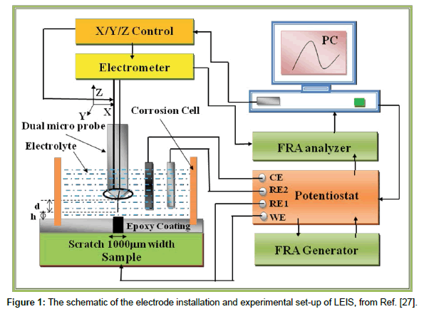
The LEIS measurements were performed using Model 470 scanning electrochemical work station, which comprises a Potentioste/ Galvanostate/FRA (model 3300) with lock-in amplifier, environmental tri-cell system, a video microscope system to position the micro-probe over the working electrode (WE). The schematic of the electrode installation and experimental set-up of LEIS is shown in Figure 1 [27]. Scratched epoxy coated carbon steel was a working electrode (WE) while saturated calomel electrode (SCE) and a graphite rod were used as the reference and auxiliary electrodes, respectively. The relative location of the microprobe to the WE was monitored by the camera system, which can be adjusted by a stepper motor in the x, y, z directions. The scanning microprobe was operated in two modes. The first mode was used for LEIS measurements. The microprobe having a 5-6 μm tip was set directly above the scratched epoxy coated carbon steel to measure the typical impedance response. The distance between the tip of the microprobe and the surface of the WE was ~ 50 μm, which was adjusted and monitored with the help of a video camera TV system, supplied along with the workstation. During LEIS measurements, an AC amplitude signal of 50 mV was applied to the electrode system. The frequency range used for the study was 20,000 to 0.1 Hz. The second mode was used for LEIS mapping at a fixed frequency of 10 Hz. The tip of the microprobe was stepped over a designated area of the electrode surface. The scanning was performed by the moving of the tip of the microprobe in the x-y axis while the x-y scales were set as a 7 × 1 mm. The step size (100 × 200 μm in x-y direction) was controlled to obtain a plot of 71 lines × 6 lines. The 3D plots were obtained from 3D Isoplot software. Specimens were mounted horizontally facing upwards. Before all experiments, the scratched epoxy coated carbon steels (WE) was kept at open-circuit potential (OCP) in the test solution for 1800 s and LEIS measurements were made at their respective OCP’s for different time intervals for 1-10 h and 1-5 days of immersion.
Results and Discussion
LEIS measurements for 1-10 h immersion
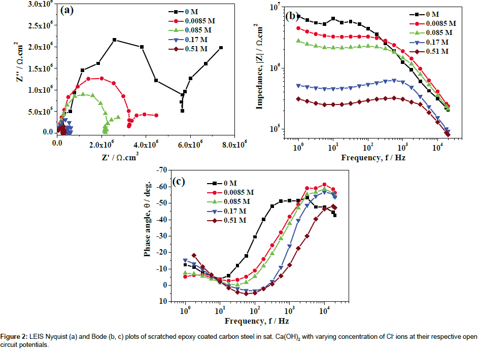
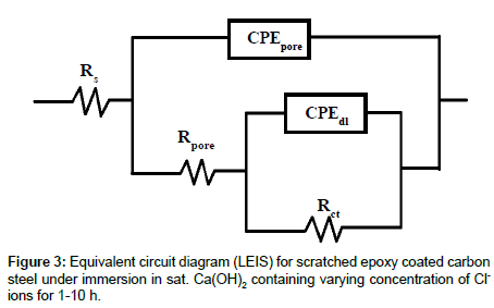
LEIS measurements performed on scratched epoxy coated carbon steel in sat. Ca(OH)2 and sat. Ca(OH)2 with 0.0085, 0.085, 0.17 and 0.51 M for 1-10 h. LEIS Nyquist plots of scratched epoxy coated carbon steel in sat. Ca(OH)2 with varying concentration of Cl- ions for 5 h are shown in Figure 2a. The corresponding Bode impedance and Bode phase angle plots are shown in Figure 2b and 2c. It is evident from Figure 2a that the capacitive part at high frequency range is associated with the pore resistance and its corresponding capacitance at the defect of steel surface. The capacitive part in the low frequency region is related to the double layer capacitance and charge-transfer resistance of corroding steel at the defect of base metal. Since, the LEIS is measured at single point at the defect site, the measured impedance at high frequency corresponds to the pore impedance during 1-10 h immersion [13]. The proposed electrical circuit model is shown in Figure 3. In this model, Rs represents the solution resistance while Rpore and CPEpore correspond to the pore resistance and the corresponding pore capacitance, while Rct and CPEdl are the charge transfer resistance and double layer capacitance of the system, respectively. The impedance of CPE is given by ZCPE=1/Q(jω)n, Where ‘n’ is the CPE exponent. The capacitance element Q (CPE) will be pure capacitance when n=1 while it will be pure resistance when n=0. Q is called as CPE when 0<n<1 and it prevails under conditions of surface heterogeneity [29]. The local electrochemical parameters derived after fitting the LEIS data are shown in Figure 4. Since, the value of ‘n’ lies between 0.58 and 0.92 in sat. Ca(OH)2 with varying concentration of Cl- ions, the choice of CPE as the circuit element seems to be appropriate. The observed impedance for scratched epoxy coated carbon steel is decreased with an increase in concentration of Cl- ions in sat. Ca(OH)2 (Figure 2a and 2b). This is clearly indicated by the depressed semicircles (Figure 2a) with an increase concentration of Cl- ions in sat. Ca(OH)2. The pore resistance, Rpore of scratched epoxy coated carbon steel is decreased from the range of 3.93 × 10⁶ to 2.75 × 10⁵ ohm.cm2 with the corresponding increase in pore capacitance, CPEpore from 2.75 × 10⁻⁹ to 1.48 × 10⁻⁷ S.sn.cm-2 with an increase in concentration of Cl- ions. The charge transfer resistance, Rct decreases from 6.38 × 10⁶ to 2.84 × 10⁶ ohm.cm2 with corresponding increase in double layer capacitance, CPEdl from 5.53 × 10⁻⁸ to 6.80 × 10⁻⁶ S.sn.cm-2 with an increase in concentration of Cl- ions in sat. Ca(OH)2 respectively. However, the corrosion resistance values of coated steel in sat. Ca(OH)2 with each concentration Cl- ions are not changed significantly with increase in immersion time from 1-10 h. In the absence of Cl- ions, inhibitive ability of the OH- ions are responsible for the formation of better passive film, while the presence of Cl- ions in sat. Ca(OH)2, promotes preferential adsorption of Cl- ions on the electrode surface and enhances the corrosion rate of steels [30,31]. In the presence study, the significant decrease in corrosion resistance is observed for higher concentration of Cl- ions (0.17 and 0.51M). The decrease in impedance with an increase in concentration of Cl- ions in in sat. Ca(OH)2 is due to the increasing the local dissolution of Fe.
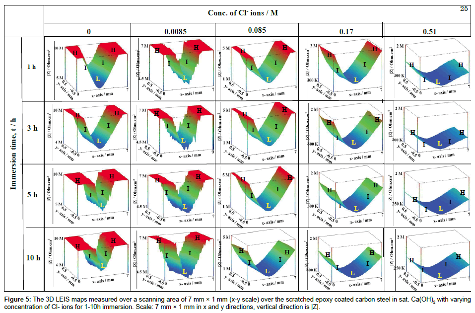
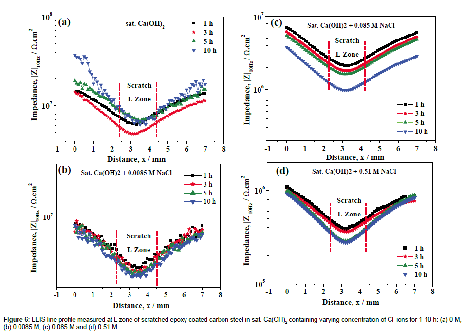
The corrosion performance of scratched epoxy coated carbon steel is to be observed at low frequency in EIS measurements. Hence, the LEIS are performed at low frequency of 10 Hz over the scratch and coated area. This provides a better understanding of the corrosion mechanism over the designated area. The LEIS maps acquired at different zones (scratch, scratch front and coated area) of the same sample covering a large area is useful to get a better understanding of the rate of corrosion at these zones. The 3D LEIS maps measured over a scanning area of 7 mm × 1 mm (x-y scale) over the scratched epoxy coated carbon steel in sat. Ca(OH)2 with varying concentration of Cl- ions are shown in Figure 5. In Figure 5, |Z| represents the measured impedance (3-D impedance distribution along the x-y axis) over the scratched epoxy coated carbon steel, which is an indicator of the electrode stability at various individual points. The magnitude of |Z| is represented by different color shades; blue, light blue, light green, dark green and red, in the order of increasing |Z| (Figure 5). It is evident that the |Z| is high over the coating (represented as zone H), moderate in the interfacial region between the coating and scratched area (represented as zone I) and low in the scratched area (represented as zone L). The average |Z| measured at zone H is above ~ 1 × 10⁷ ohm.cm2 whereas it decreased to ~ 6 × 10⁶ ohm.cm2 in zone L in a sat. Ca(OH)2, while the impedance values are maintained with immersion time for 1-10 h. By the addition of Cl- ions to the sat. Ca(OH)2, the average |Z| starts to decrease both at the H zone as well as at the L zone from 1 × 10⁷ to 1 × 10⁶ ohm.cm2 and 4.76 × 10⁶ to 2.88 × 10⁵ ohm.cm2 respectively. These inferences indicate that the local corrosion process is enhanced by the Cl- ions due to the dissolution of Fe from the scratch area. However, the addition of 0.0085 M of Cl- ions in sat. Ca(OH)2 does not show any significant change in impedance values at L zone. The observed results are in line with our previously reported results [27].
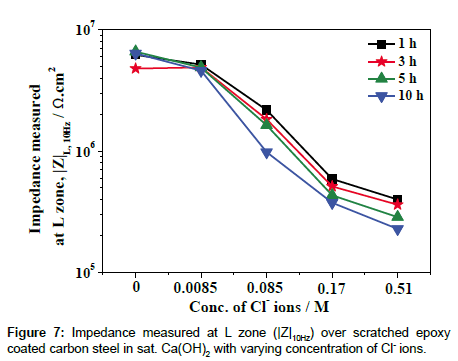
The corresponding LEIS line profiles are shown in Figure 6, which clearly indicates the decrease in |Z| in the L-zone due to the higher dissolution of Fe at the scratched area with increase in concentration of Cl ions. The |Z| measured at the L zone as a function of concentration of Cl- ions is plotted in Figure 7. It is evident from the Figure 7 that an increase in concentration of Cl- ions has led to an increase in the rate of corrosion of scratched epoxy coated steel at the L zone. The shape of the curves in Figure 6 further confirms the inferences made from Figure 5 that at higher concentration of Cl- ions, the extent dissolution of Fe at scratched area becomes higher. Further, the continuous decrease in |Z| over the coating and the scratched area indicates that a continuous dissolution of Fe and the easy availability of corrosive intermediate species (containing Fe(II)/Fe(III) compounds) near the scratched area which could be deposited over the coating due to the higher pH from the bulk solution [32]. However, there is no sign of additional defects over the coating that has been observed from the LEIS maps with the addition of Cl- ions to the sat. Ca(OH)2. On the other hand, the decrease in |Z| over the coating might be due to the water uptake of the epoxy coating [10,33]. Further, the experiments have been conducted by long term immersion for 1-5 days on the better understanding of local corrosion process at scratch and coating area of scratched epoxy coated carbon steel in varying concentration of Cl- ions.
LEIS measurements for 1-5 days of immersion
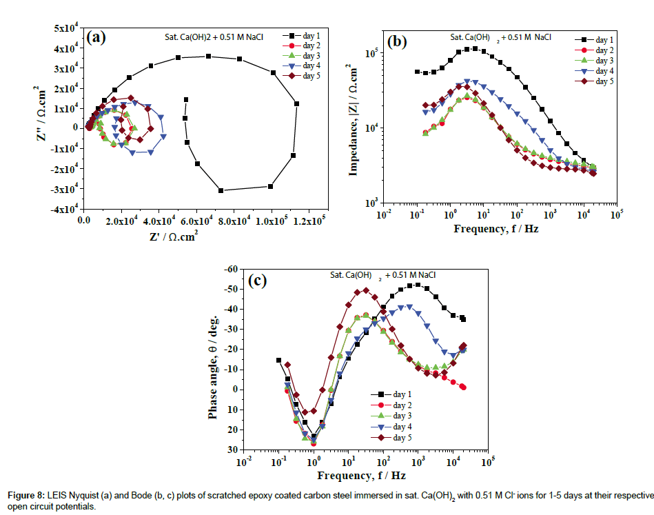
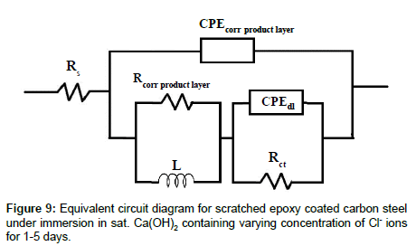
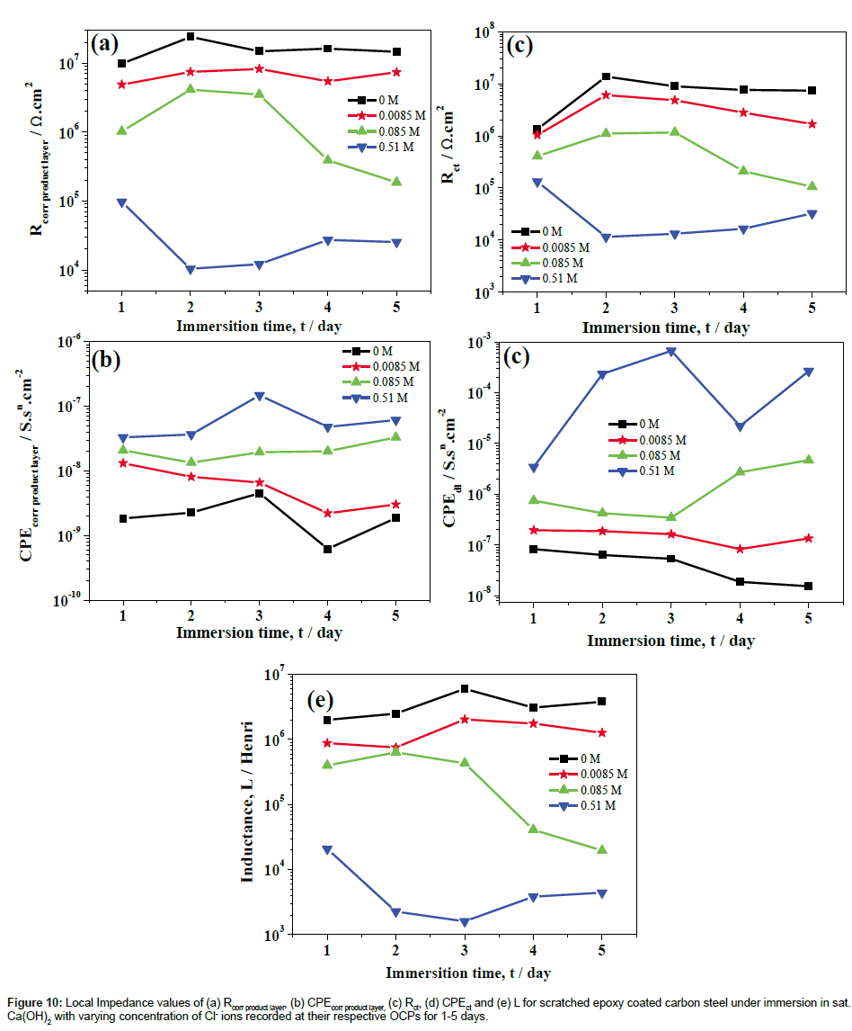
LEIS Nyquist plots of scratched epoxy coated carbon steel in sat. Ca(OH)2 with 0.51 M Cl- ions for 5 days of immersion are shown in Figure 8a. The corresponding Bode impedance and Bode phase angle plots are shown in Figures 8b and 8c. It is evident from Figure 8a that the capacitive part at high frequency range is associated with the corrosion product layer at scratch, the inductive loop at intermediate frequencies is due to the adsorption of corrosion species involved in the local corrosion process and, the capacitive part in the low frequency region is related to the double layer capacitance and charge transfer resistance of corroding steel [34,35]. The proposed electrical circuit model and fittings values are shown in Figures 9 and 10 for sat. Ca(OH)2 with varying concentration of Cl- ions respectively. In this model, Rs represents the solution resistance while Rcorr product layer and CPEcorr product layer correspond to the resistance of corrosion product layer and the corresponding capacitance of the corrosion product layer, respectively. The L is the inductance of adsorbed intermediate corrosive species involved in the local corrosion process while Rct and CPEdl are the charge transfer resistance and double layer capacitance of the system, respectively. It is evident from Figure 10, the resistance of corrosion product layer is decreased from 1.01 × 10⁵ to 1.24 × 10⁴ ohm. cm2 (one fold decrease) by the addition 0.51 M Cl- ions from 1st to 3rd day of immersion. With increase in immersion time from 3rd to 5th day, resistance of corrosion product layer is slightly increased to 2.66 × 10⁴ ohm.cm2. This is due to the formation of corrosion products that makes difficulty in charge transfer at the interface of corrosion product layer and bare steel interface. However, the charge transfer is not completely restricted due to the formation of intermediate corrosion products [21]. The resistance of the corrosion product layer formed on scratched area is higher (9.47 × 10⁶ to 1.49 × 10⁷ ohm.cm2) in sat. Ca(OH)2 for 1-5 day of immersion. In the presence of 0.085 M Cl- ions, the resistance of the corrosion product layer is initially increased from 9.95 × 10⁵ to 3.57 × 10⁶ ohm.cm2 then it is decreased from 3.57 × 10⁶ to 1.81 × 10⁵ ohm.cm2 with increase in immersion time for 1-5 days. On the other hand, the resistance of Rcorr product layer is higher in sat. Ca(OH)2 (1 × 10⁷-1.40 × 10⁷ ohm.cm2) as compared to 0.0085 M Cl- added solution (4.85 × 10⁶-7.66 × 10⁶ ohm.cm2) for 1-5 days of immersion. In this case, the Rcorr product layer is increased with immersion time for 0 and 0.0085 M Cl- ions as compared to other concentration of Cl- ions added solutions. These inferences clearly indicate that Rcorr product layer depends on Cl- ion concentrations and the corresponding chemical compositions of corrosion product layers [23,36]. Moreover, Cl- to OH- ion concentration is also important factor that determines the chemical compositions of the corrosion product layers [23]. The charge transfer resistance, Rct of corroding steel is increased from 1.29 × 10⁶ to 1.28 × 10⁷ ohm.cm2 1-2 days of immersion time and it retained at 7.93 × 10⁶ ohm.cm2 with increase in immersion time in the absence of Cl- ion solution. Similarly, the Rct values are increased from 1.05 × 10⁶ to 6.49 × 10⁶ for 1st day of immersion and then sustained in the resistance values (2.90 × 10⁶) with increase in immersion time in 0.0085 M Cl- ion solution. The Rct values (absence of Cl- ions) are comparable with Rct values of 0.0085 M Cl- ions increase in immersion time. The increase in concentration of Cl- ions in to 0.085 M, the Rct values are increased initially from 4.20 × 10⁵ (day 1) to 1.16 × 10⁶ ohm.cm2 (day 2) and then start to decrease with immersion time from 1.16 × 10⁶ to 1.01 × 10⁵ ohm.cm2. However, in case of sat. Ca(OH)2 with 0.51 M Cl, the Rct values start to decrease from 1.24 × 10⁵ to 1.12 × 10⁴ ohm.cm2 for 1st to 2nd day of immersion then starts to increase slightly from 1.12 × 10⁴ to 3.18 × 10⁴ ohm.cm2 with increase in immersion time.
The various concentrations of chloride threshold levels on the corrosion resistance of steels have been reported by various researchers [28,37,38]. Li and Sagues [37] studied the chloride threshold level in saturated Ca(OH)2 was found to be 0.01-0.04 M. Gouda [38] has been reported that the 0.007 M could be the chloride threshold level (added as NaCl) in a saturated Ca(OH)2 solution, which did not affect the passivity of the steel. Moreno et al. [28] have been reported that the 0.02% Cl (0.0034 M) addition in to the sat. Ca(OH)2 solution has no appreciable change in anodic behavior of steel and it was observed that Cl- ion concentration equal to or higher than 0.05% (0.0085 M) induce pitting of the steel. However, the epoxy-coated steel can gave a good protection; long term performance even on severe exposure to chloride conditions have been reported with considering properly coated and handled steels [39,40]. Al-Amoudi et al. [40] found that the chloride threshold level of epoxy-coated steel with various degrees of coating damage (1 and 2%) and the chloride threshold level was about 2 and 0.4% (0.35 and 0.068 M) by weight of cement respectively. In the present study, 0.0085 M of Cl- ions in sat. Ca(OH)2 is found to be comparable with absence of Cl- ions (Figures 4, 7 and 10), beyond 0.0085 M of Clions led to the significant decrease in corrosion resistance of scratched epoxy coated carbon steel.
The 2D LEIS maps acquired at scanning area of 7 mm × 1 mm (x-y scale) over the scratch and coated area of carbon steel in sat. Ca(OH)2 with 0.51 M of Cl- ions for 1, 3 and 5 days of immersion are shown in Figure 11. In Figure 11, the different color shades represents the measured impedance, |Z| distribution along the x-y axis. It is evident from (Figure 11a, 11b and 11c) shows the measured impedance over the scratch area, while the Figure 11d, 11e and 11f shows the measured impedance over the coated area. The significant decrease in impedance at scratch is observed with increase in immersion time from 1st day to 3rd day (2.5 × 10⁵ to 3.5 × 10⁴ ohm.cm2) and then slightly increased at 5th day (5 × 10⁴ ohm.cm2) at scratch area. In addition, the corrosion at scratch area is broadened in 3rd day of immersion due to direct penetration of electrolyte (arrow marks in Figure 11b), while the additional corrosion spots could be found in over the coated area (arrow marks shown in Figure 11e). The corrosion at scratch area is restricted due to the formation corrosion products with increase in immersion time to 5th day (Figure 11c). The additional corrosion spots at scratch front and away from the scratch could be extended with larger corrosion spots (Figure 11e and 11f). This is mainly due to the formation of corrosion products at the scratch area (at high pH solutions) eventually corrosion starts at some other places (around the corrosion spots) [21]. The observed results are in line with LEIS parameters (Figure 10) for 0.51 M Cl- ions containing solution.
Figure 11: 2D LEIS maps measured over a scanning area of 7 mm × 1 mm (x-y scale) over the scratched epoxy coated carbon steel in sat. Ca(OH)2 with 0.51 M of Cl- ions : (a, b and c) at scratch area, (d, e and f) over coating area for 1, 3 and 5 days of immersion respectively ; different color shads indicates difference in |Z| at different zones.
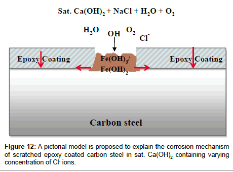
Based on the inferences made in the present study, a pictorial model is proposed to explain the corrosion mechanism of scratched epoxy coated carbon steel in sat. Ca(OH)2 with varying concentration of Cl- ions (Figure 12). The dissolution kinetics is increased at scratch area of epoxy coated steel with increase of concentration of Cl- ions. In case of immersion, the hydroxides (Fe(OH)2 or Fe(OH)3) are formed at the scratched area while at a later stage it is converted to FeOOH in the presence of dissolved oxygen [41]. The formation of green rust compounds, GR(Cl-) are also possible as an intermediate corrosion products when the Cl- ions are present in sat. Ca(OH)2 [42,43]. However, the GR(Cl-) could be converted easily to (γ, α and β)-FeOOH in the presence oxygen as final corrosion products with immersion time. Once the corrosion products (Fe(OH)2 or Fe(OH)3 or FeOOH) are formed at the scratch area, the oxygen diffusion could be restricted and eventually the cathodic process could occurs at some other places away from the scratch or scratch front leads to the cathodic disbandment of coating (arrow marks shown in Figure 12) leads to coating degradation [21]. It has been shown that 1000 μm diameter defect with relatively open geometry did not show any blocking effect, which was mainly dominated by the diffusion process in near-neutral pH solution. Moreover, corrosion product formed at defects was left easily from the large defect, while the diffusion of corrosive species could participate on the local corrosion process [13]. Similarly, Philippe et al. [11] have been reported that the degradation of polyester coil coated galvanized steel with 250 μm diameter artificial defect in NaCl by LEIS at different time intervals. It was found the additional corrosion spots away from original defect, while the original defect was still showed the occurrence of corrosion in NaCl due to the diffusion of active species through a plug of corrosion product at the defect. Jorcin et al. [14] have explored the use of LEIS mapping to assess the delamination phenomena at the steel/epoxy-vinyl primer interface in NaCl and identified that the delamination has originated from the artificial defects. The corrosion products formed at the defect acts as anodic zones, which hinders the transport of O2 at this defect site and favors the reduction of O2 at cathodic sites, especially over the coated area, which in turn promotes cathodic delamination at the steel-coating interface. In the present study, the corrosion occurs at initially at the defect area due to the preferential adsorption Cl- ions and due to the high pH (12.7) of solution it could be deposited as a corrosion product at the scratch area. Hence, the corrosion at scratch is restricted due to the formation of corrosion products. The additional corrosion spots (zones) formed around the original scratch area which is generated by the under-film corrosion beginning at the scratch front and away from the scratch due to the cathodic reactions. This has been clearly visualized by LEIS mapping which provides better understanding on the corrosion mechanism of scratched epoxy coated carbon steel in sat. Ca(OH)2 in Cl- ions containing solutions.
Conclusion
The influence of varying concentration of chloride ions on the local corrosion behavior of scratched epoxy coated carbon steel in sat. Ca(OH)2 is investigated by in-situ manner using LEIS. The LEIS responses measured at the defect are attributed to the pore impedance in the high-frequency range and an interfacial corrosion reaction in the low-frequency range of corroding steel within 1-10 h immersion. The pore resistance, Rpore of scratched epoxy coated carbon steel is decreased from the range of 3.93 × 10⁶ to 2.75 × 10⁵ ohm.cm2, the charge transfer resistance; Rct is also decreased from 6.38 × 10⁶ to 2.84 × 10⁶ ohm.cm2 with increase in concentration of Cl- ions from 0-0.51 M. The LEIS maps acquired at 10 Hz provides a better recognition of anodic and cathodic areas on the local corrosion process of scratched epoxy coated carbon steel. The decrease of change in |Z| range from 6.27 × 10⁶ to 4.85 × 10⁶ ohm.cm2 is marginal by the addition of 0.0085 M Cl- ions into the sat. Ca(OH)2, whereas it decreased from 4.85 × 10⁶ to 2.88 × 10⁵ ohm. cm2 with increase in concentration of Cl ions from 0.0085 to 0.51 M. The |Z| measured by LEIS reveals a continuous decrease in impedance at the scratch due to the higher dissolution of Fe with an increase in concentration of Cl- ions, which is further validated by the variation in |Z| by LEIS maps. This clearly indicates that an increase of NaCl concentration leads to the significant increase in the corrosion rate of the scratched epoxy coated carbon steel due to preferential adsorption of Cl- ions on the electrode.
On the other hand, LEIS Nyquist plots clearly showed that the measured impedance at high frequency is related to resistance of corrosion product layer (Rcorr product layer) formed at the defect which acts as anodic area and the low frequency part are related to corroding of carbon steel with immersion of 1-5 days. The resistance of corrosion product layer is decreased from 1.01 × 10⁵ to 1.24 × 10⁴ ohm.cm2 (one fold decrease) by the addition of 0.51 M Cl- ions from 1st to 3rd day of immersion. With increase in immersion time from 3rd to 5th day, resistance of corrosion product layer is slightly increased to 2.66 × 10⁴ ohm.cm2. This is due to the formation of corrosion products that makes difficulty in charge transfer at the interface of corrosion product layer and bare steel in which the charge transfer is not completely restricted due to the formation of intermediate corrosion products. The Rcorr product layer values are much higher in sat. Ca(OH)2 and with 0.0085 M Cl- ions as compared to 0.085 and 0.51 M Cl- ions and it varied slightly higher/lower impedance values. These inferences indicate that Rcorr product layer depends on Cl- ion concentrations and the corresponding chemical compositions of corrosion product layers. This has been clearly indicated in the 2D topographic images that corrosion occurred at scratch along with scratch front as well as away from the scratch with increase in immersion time. The different color zone at scratch area revealed that the formation of corrosion products followed by the localized corrosion due to the porous nature of the passive layer. The 2D topographic image results are well agreement with LEIS parameters for 1-5 days of immersion. No significant reduction in LEIS values at 1-10 h immersion, |Z| values at L zone, LEIS in 1-5 days of immersion in 0 and 0.0085 M Cl- ions. This is due to the presence of sufficient concentration of inhibitive OH- ions in solution. The inferences made in the present study points out that beyond 0.0085 M NaCl is likely to increase the corrosion rate of scratched epoxy coated carbon steel.
Acknowledgements
This work was supported by Council for Science, Technology and Innovation (CSTI), Cross-ministerial Strategic Innovation Promotion Program (SIP), “Infrastructure maintenance, renovation and management” (Funding agency: JST).
References
- Mansfeld F (1993) Models for the impedance behavior of protective coatings and cases of localized corrosion. Electrochim Acta 38: 1891-1897.
- Walter GW (1986) A review of impedance plot methods used for corrosion performance analysis of painted metals. Corros Sci 26: 681-703.
- He J, Gelling VJ, Tallman DE, Bierwagen GP (2000) A scanning vibrating electrode study of chromated‐epoxy primer on steel and aluminum. J Electrochem Soc 147: 3661-3666.
- Maile FJ, Schauer T, Eisenbach CD (2000) Evaluation of the delamination of coatings with scanning reference electrode technique. Prog Org Coat 38: 117-120.
- Nazarov A, Le Bozec N, Thierry D, Le Calvé P,Pautasso JP (2012) Scanning kelvin probe investigation of corrosion under thick marine paint systems applied on carbon steel. Corrosion 68: 720-729.
- Bastos AC, Simo˜es AM, Gonza´lez S, Gonza´lez-Garcı´a Y,Souto RM (2004) Imaging concentration profiles of redox-active species in open-circuit corrosion processes with the scanning electrochemical microscope. Electrochem Commun 6: 1212-1215.
- Lillard RS, Kruger J, Tait WS, Moran PJ (1995) Using local electrochemical impedance spectroscopy to examine coating failure. Corrosion 51: 251-259.
- Van der Weidje DH, van Westing EPM, der Wit JWH (1996) EIS measurements on artificial blisters in organic coatings. Electrochim Acta 41: 1103-1107.
- Cambier SM, Verreault D, Frankel GS (2014) Raman investigation of anodic undermining of coated steel during environmental exposure. Corrosion 70: 1219-1229.
- Nguyen T, Martin JW (2004) Modes and mechanisms for the degradation of fusion bonded epoxy-coated steel in a marine concrete environment. JCT Research 1: 81-92.
- Philippe LVS, Walter GW, Lyon SB (2003) Investigating localized degradation of organic coatings comparison of electrochemical impedance spectroscopy with local electrochemical impedance spectroscopy. J Electrochem Soc 150: B111-B119.
- Zou F, Thierry D (1997) Localized electrochemical impedance spectroscopy for studying the degradation of organic coatings. Electrochim Acta 42: 3293-3301.
- Zhong C, Tang X, Cheng YF (2008) Corrosion of steel under the defected coating studied by localized electrochemical impedance spectroscopy. Electrochim Acta 53 4740-4747.
- Jorcin JB, Aragon E, Merlatti C, Pébère N (2006) Delaminated areas beneath organic coating: A local electrochemical impedance approach. Corros Sci 48: 1779-1790.
- Raman V, Nishimura T (2009) Monitoring of Environmental Factors and Corrosion Analysis of Reinforcing Steel in Mortar. Mater Trans 50: 799-805.
- Dong Y, Zhou Q (2014) Relationship Between Ion Transport and the failure behavior of epoxy resin coatings. corros Sci 78: 22-28.
- Vakili H, Ramezanzadeh B, Amini R (2015) The corrosion performance and adhesion properties of the epoxy coating applied on the steel substrates treated by cerium-based conversion coatings. Corros Sci 94: 466-475.
- Nishimura T (2016) Corrosion estimation of epoxy coated high tensile strength steel measured by statistical analysis and TEM - EELS. Mater Trans 57: 52-57.
- Souto RM, Gonza´lez-Garcia Y, Gonza´lez S, Burstein GT (2004) Damage to paint coatings caused by electrolyte immersion as observed in situ by scanning electrochemical microscopy. Corros Sci 46: 2621- 2628.
- Souto RM, Gonza´lez-Garcia Y, Gonza´lez S (2005) In situ monitoring of electroactive species by using the scanning electrochemical microscope. Application to the investigation of degradation processes at defective coated metals. Corros Scie 47: 3312-3323.
- Balusamy T, Nishimura T (2016) In-situ corrosion monitoring of scratched epoxy coated carbon steel in saturated Ca(OH)2 with or without 3% NaCl by scanning electrochemical microscopy and electrochemical impedance spectroscopy. Amer J Anal Chem 7: 533-547
- Schaller RF, Thomas S, Birbilis N, Scully JR (2015) Spatially resolved mapping of the relative concentration of dissolved hydrogen using the scanning electrochemical microscope. Electrochem Commun 51: 54-58.
- Grousset S, Kergourlay F, Neff D, Foy E, Gallias JL, et al. (2015) In situ monitoring of corrosion processes by coupled micro-XRF/micro-XRD mapping to understand the degradation mechanisms of reinforcing bars in hydraulic binders from historic monuments. J Anal At Spectrom 30: 721-729.
- Lin B, Hu R, Ye C, Li Y, Lin C (2010) A study on the initiation of pitting corrosion in carbon steel in chloride-containing media using scanning electrochemical probes. Electrochim Acta 55: 6542-6545.
- Glass GK, Buenfeld NR (1997) The presentation of the chloride threshold level for corrosion of steel in concrete. Corros Sci 39: 1001-1013.
- Shi X, Nguyen TA, Kumar P, Liu Y (2011) A phenomenological model for the chloride threshold of pitting corrosion of steel in simulated concrete pore solutions. Anti-Corros Method Mater 58: 179-189.
- Balusamy T, Nishimura T (2016) In-situ monitoring of local corrosion process of scratched epoxy coated carbon steel in simulated pore solution containing varying percentage of chloride ions by localized electrochemical impedance spectroscopy. Electrochim Acta 199: 305-313.
- Moreno M, Morris W, Alvarez MG, Duff GS (2004) Corrosion of reinforcing steel in simulated concrete pore solutions Effect of carbonation and chloride content. Corros Sci 46:2681-2699.
- Orazem ME, Tribollet B (2008) Electrochemical Impedance Spectroscopy. John Wiley & Sons, USA.
- Saremi M, Mahallati E (2002) A study on chloride-induced depassivation of mild steel in simulated concrete pore solution.Cem Concr Res 32: 1915-1921.
- Burstein GT, Davies DH (1980) The effects of anions on the behaviour of scratched iron electrodes in aqueous solutions. Corros Sci 20: 1143-1155.
- Sagoe-Crentsil KK, Glasse FP (1993) Green rust, Iron solubility and the role of chloride in the corrosion of steel at high pH. Cem Concr Res 23: 785-791.
- Park JH, Lee GD, Ooshige H, Nishikata A, Tsuru T (2003) Monitoring of water uptake in organic coatings under cyclic wet-dry condition. Corros Sci 45: 1881-1894.
- Zhang GA, Cheng YF (2009) Micro-electrochemical characterization of corrosion of welded X70 pipeline steel in near-neutral pH solution. Corros Sci 51: 1714-1724.
- Meng GZ, Zhang C, Cheng YF (2008) Effects of corrosion product deposit on the subsequent cathodic and anodic reactions of X-70 steel in near-neutral pH solution. Corros Sci 50: 3116-3122.
- Nishimura T, Katayama H, Noda K, Kodama T (2000) Electrochemical behavior of rust formed on carbon steel in a wet/dry environment containing chloride ions. Corrosion 56: 935-941.
- Li L, Sagues AA (1999) Effect of chloride concentration on the pitting and repassivation potentials of reinforcing steel in alkaline solutions. Corrosion/99, paper No. 567, NACE, Houston, TX.
- Gouda VK (1970) Corrosion and corrosion inhibition of reinforcing steel 1: Immersion in alkaline solution Br. Corros J 5: 198-203.
- Erdogdu S, Bremner TW, Kondratova IL (2001) Accelerated testing of plain and epoxy-coated reinforcement in simulated seawater and chloride solutions. Cem Concr Res 31: 861-867
- Al-Amoudi OSB, Maslehuddin M, Ibrahin M,(2004) Long-term performance of fusion-bonded epoxy-coated steel bars in chloride-contaminated concrete. ACI Material Journal 101: 303-309.
- Volpi E, Olietti A, Stefanoni M, Trasatti SP (2015) Electrochemical characterization of mild steel in alkaline solutions simulating concrete environment. J Electroanaly Chem 736: 38-46.
- Génin JMR, Dhouibi L, Refait PH, Abdelmoula M, Triki E (2002) Influence of phosphate on the corrosion products of iron in chloride-polluted concrete- simulating solutions: ferrihydrite vs green rust. Corrosion 58: 467-478.
- Dhouibi L, Refait PH, Triki E, Génin JMR (2006) Interactions between nitrites and Fe (II)-containing phases during corrosion of iron in concrete-simulating electrolytes. J Mater Sci 41: 4928-4936.
Relevant Topics
Recommended Journals
Article Tools
Article Usage
- Total views: 15184
- [From(publication date):
August-2016 - Jul 04, 2025] - Breakdown by view type
- HTML page views : 14038
- PDF downloads : 1146

