Research Article Open Access
Laser Cleaning Treatment and its Influence on the Surface Microstructure of CFRP Composite Material
Zhan X1,2*, Gao C1, Lin W1, Gu C1, Sun W2 and Wei Y11College of Material Science and Technology, Nanjing University of Aeronautics and Astronautics, Nanjing 211106, PR China
2Department of Materials Science and Engineering, The Ohio State University, Columbus, OH 43210, USA
- *Corresponding Author:
- Zhan X
College of Material Science and Technology
Nanjing University of Aeronautics and Astronautics
Nanjing 211106, PR China
Tel: 86-10-82865135
E-mail: xiaohongzhan_nuaa@126.com
Received Date: March 17, 2017; Accepted Date: April 21, 2017; Published Date: April 27, 2017
Citation: Zhan X, Gao C, Lin W, Gu C, Sun W, et al. (2017) Laser Cleaning Treatment and its Influence on the Surface Microstructure of CFRP Composite Material. J Powder Metall Min 6: 165. doi:10.4172/2168-9806.1000165
Copyright: © 2017 Zhan X, et al. This is an open-access article distributed under the terms of the Creative Commons Attribution License, which permits unrestricted use, distribution, and reproduction in any medium, provided the original author and source are credited.
Visit for more related articles at Journal of Powder Metallurgy & Mining
Abstract
Carbon fiber reinforced polymer (CFRP) is one of the most important construction materials in civil aircraft manufacturing. In the current paper, effects of laser surface treatment on the surface microstructure of the CFRP are involved. And the influence of laser surface treatment parameters on shear strength and failure pattern are considered. The optimized parameters including laser scanning speed, laser power, frequency and power density are expected to ensure that the resin and all kinds of pollutants on the surface are cleaned. It is indicated that laser power density significantly influences the surface morphology. The surface with continuous and integrated fibers is helpful for adhesive bonding and is acquirable under appreciate parameters. Maximum shear strength (27 MPa) of adhesively bonded joint was obtained after laser surface treatment.
Keywords
Carbon fiber reinforced polymer (CFRP); Laser treatment; Adhesively bonded joint
Introduction
Due to the high strength and specific stiffness, density and small thermal expansion coefficient, and good dimensional stability, composite material especially carbon fiber reinforced polymer (CFRP) composite becomes one of the most important construction materials in civil aircraft engineering [1]. On the other hand, compared to the metal, CFRP composite displays poor impact resistance and low strength between surface layers and substrate which lead to the difficulty in assembly connection of the structure and high technical requirements [2]. Adhesively bonded joints is recommended instead of the traditional riveting joints and welding joints in the aerospace products due to many advantages including improved impact behavior and energy absorption [3], less vibration and sound deadening, good air tightness and an ability of keeping the integrity of the materials [4,5].
Surface condition is an important factor for bonding [6], which affects the strength of adhesively bonded joints significantly [7-19]. Chabot and Bonk [5] investigated adhesive bonding of composite material made by aluminum alloy and stainless steel respectively. The samples surfaces were separately coated on three kinds of adhesive first and then used AF-163-2K adhesive film to bonding samples. Schäfer et al. [15] investigated an atmospheric-pressure plasma jet (APPJ)-based surface treatment for the structural (τB>15 MPa) adhesive bonding of polyamide 6 (PA6) composites and their results showed that APPJ led to an increase in surface free energy, oxygen concentration, and the number of functional groups. Furthermore, the surface topography was significantly modified by exposing to APPJ. Schulte and Baron [16] carried out load and failure analyses of CFRP laminates by means of electrical resistivity measurements. Zhu et al. [17] aimed at designing, manufacturing and testing of two different nonlinear shear connectors made of fiber reinforced polymer composites for the formwork: (1) non-directional, cylindrical shear-cones; and (2) directional, cubical shear-cones with one side beveled.
Material surface can be improved through laser technology. Akman et al. [18] investigated the effects of Nd:YAG laser and 17% EDTA treatment on root-dentin mineral content. Badziak found that the pressure of the shock generated in the plastic layer is relatively weakly influenced by the preplasma and at the pulse intensity of 6510 16 W/cm2 [14]. Bartkowska et al. [19] remelted boronickelized C45 steel by laser surface modification. It can be seen that laser modification improved wear resistance, cohesion as well as low-cycle fatigue of the boronickelized layer. Surface morphology, free energy, oxidation, and roughness of titanium and 316 L grade stainless steel were changed by nanosecond pulsed laser processing conclusion to investigate the surface wettability alteration [16].
With the development of high power laser, laser technology has entered into the field of nonmetallic material surface treatment, and is rapidly developed in recent years [17]. Considering its fast heating and cooling, laser surface treatment can be applied to surface strengthening and coating treatment [18]. By changing laser processing parameters, it can be used to substrate surface melting, ablation [19,20], inducing surface nanostructures [21], and phase transformation strengthening [22]. Ingram et al. [23] studied the optical characterization of carbonnanoparticles (CNPs) synthesized by the laser ablation of solids in liquids technique. However, so far there are few studies on applications of laser pretreatment used in the adhesive bonding process. In the present paper, effects of processing on the surface of CFRP plate and the strength of CFRP adhesively bonded joints were investigated. The purpose of this article is to consider the effect of superficial processing parameters on shear strength and failure pattern, thus filtrating the optimal parameters.
Experimental Section
The CFRP plates with T800 carbon fiber embed are used in this study. The CFRP plates contained 8 layers and every two layers are often interlaced. The adhesive used throughout this investigation is E-120 HP. The process parameters and shear strength of E-120 HP can be seen in Table 1. In this thesis, experiment is carried out using an IPG-50 W (1064 nm) laser operated in pulsed mode. The parameters of laser processing are listed in Table 2, and laser spot diameter is 50 μm.
| Adhesive | Curing temperature (°C) | Curing time (h) | Shear strength (MPa) |
|---|---|---|---|
| Loctite E-120HP | 20 | 48 | 20-40 |
Table 1: The process parameters and shear strength of E-120HP.
| Number | Speed (V, mm/s) | Frequency (f, KHz) | Power density (Pd, Kw/cm2) |
|---|---|---|---|
| 1 | 4000 | 20 | 11.46 |
| 2 | 4000 | 60 | 22.93 |
| 3 | 4000 | 100 | 34.39 |
| 4 | 6000 | 60 | 11.46 |
| 5 | 6000 | 100 | 22.93 |
| 6 | 6000 | 20 | 34.39 |
| 7 | 8000 | 100 | 11.46 |
| 8 | 8000 | 20 | 22.93 |
| 9 | 8000 | 60 | 34.39 |
Table 2: The laser processing parameters used in this experiment.
Two laser scan directions are used on the CFRP surface which is shown in Figure 1. It should be noted that the process is carried out at room temperature and in atmospheric environment. The geometry of CFRP plate and laser scanning route are shown in Figure 2. Adhesive joints are fabricated using CFRP plates and epoxy adhesives (E-120 HP). Curing is carried out at 20°C for 48 h. The bond line thickness is set to be (t=) 0.2 mm. Prior to the adhesive bonding experiment, the surface of CFRP plates is pretreated by different methods. The adhesive bonding experiments are divided into three classes and samples are cured at room temperature for 48 h. The surface pretreatment process of three classes is shown in Table 3. A single lap adhesively bonded joint is investigated. All the samples are tested in a universal testing machine. The geometric parameters are identified as to be 100 mm, 25 mm, 2 mm (Figure 3). All the tests were conducted at room temperature (approximately 20°C) Three samples are tested for each case of joint configuration.
| Case | Surface pretreatment |
|---|---|
| 1 | immersed in acetone for 60s |
| 2 | polished with 0# sandpaper, then |
| immersed in acetone for 60s | |
| 3 | treated by laser, then |
| immersed in acetone for 60s |
Table 3: Surface pretreatment process.
Results and Discussion
Laser surface treatment results
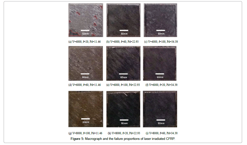
Laser treatment on composite surface is a relatively complicated physical and chemical process, results in removing dirt from surface including impurities, resin, etc. The schematic diagram of laser surface treatment is shown in Figure 4. The surface morphologies of CFRP plates are affected by the speed, frequency and laser power density during processing. Figure 5 presents the surface morphologies and the failure proportions of CFRP plates obtained using various parameters of laser treatment. As shown in Figure 5, any combinations of the experimental cases are unable to remove resin and pollutants under power density of 11.46 Kw/cm2. However, all the experimental cases can remove resin and pollutants on the surface under the power density of 22.93 Kw/cm2 and 34.39 Kw/cm2. It is difficult to distinguish the difference of the surface by direct observation; hence quantitative analysis is applied to failure proportions statistics.
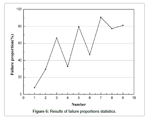
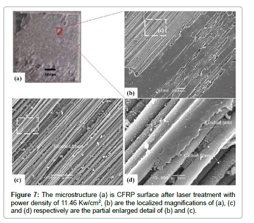
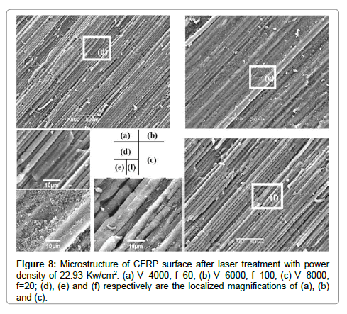
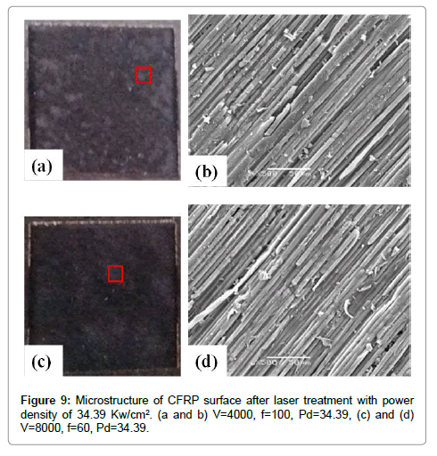
The results of statistics are shown in Figure 6. As shown in Figure 6, failure proportions (the proportion of burnt off fibers to the whole) of CFRP surface is influenced by the laser parameters. It can be seen that the failure proportion increases with increasing the power density. However speed and frequency have less influence than power density. Figure 7 shows the microstructure of the CFRP surface after laser treatment under the power density of 11.46 Kw/cm2. The surface of CFRP is not completely cleaned under the power density of 11.46 Kw/cm2. The resin is burnt and fibers are exposed obviously on the surface of CFRP. In addition, the burnt resin is found to be brittle and the non-burnt remains on the surface of CFRP plate. The exposed fiber where resin is cleaned is continuous and integrated. Ablation is not observed in the microstructure of CFRP surface after the laser treatment. Microstructures of the CFRP surface after laser treatment under the power density of 22.93 Kw/cm2 are shown in Figure 8. Different surfaces morphologies are obtained under different scanning speed and frequency. It can be seen in Figure 8, resin and pollutants on the surface are cleaned. It indicates that laser treatment is able to remove such contaminants. However, the exposed fibers are found to be fractured, shown as the arrow in Figure 8a and 8c. Figure 8b shows that exposed fibers are continuous and integrated, and there are still some resin coated on the surface of CFRP plate. Microstructures of the CFRP surface after laser treatment under the power density of 34.39 Kw/cm2 are shown in Figure 9. It is found that resin and pollutants on surface are totally cleaned under the power density of 34.39 Kw/ cm2. In addition, there are no fibers wrapped by resin and some fibers are burned off regardless of the scanning speed being changed. The continuity and integrity of the fibers can guarantee the high strength of composite material. However, the continuity of the fiber under the power density of 34.39 Kw/cm2 is destroyed compared to that under the power density of 22.93 Kw/cm2. In order to ensure the continuity and integrity of the inner fibers, the best parameters for laser scanning speed, frequency and laser power density are 6000 mm/s, 100 KHz, and 22.93 Kw/cm2 respectively.
Adhesive single lap shear (SLS) tests
Three different processing methods are applied to the CFRP before the adhesive bonding experiments. Microstructures of CFRP surfaces of the three cases are shown in Figure 10.
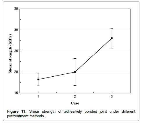
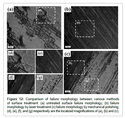
As shown in Figure 10a, most part of the surface is covered by resin or contaminant, and the fibers are partially exposed. Figure 10b displays that the fibers on the surface of the CFRP plate are broken. The continuity of the fiber is damaged after mechanical polishing. Figure 10c shows that resin and various pollutants on the surface are totally cleaned by the laser treatment. The exposed fibers are continuous and integrate. Some fibers on the surface are still wrapped by the base resin. The shear strengths of the adhesively bonded joints are measured by SLS tests. The shear strengths of adhesively bonded joint under different surface pretreatment methods are shown in Figure 11. As shown in Figure 11, the largest maximum shear strength (27 MPa) of adhesively bonded joint is obtained under caser3 pretreatment method. Shear strength increases by 36.15% compared to that without surface treatment. It indicates that laser surface treatment can improve joint strength. Meanwhile surface treatment of mechanical polishing improves the shear strength of adhesively bonded joint compared to that without surface treatment. Numerous factors influence the strength of a joint such as adhesive properties the interface of adhesive and adherent, and adherent properties. When the adhesive strength is less than that of interface bonding between adhesive and adherent, the increasing shear load will lead to the failure of adhesive firstly. The theories of destruction of adhesive interface and adherent are similar with the damage of adhesive (Figure 12). In order to determine the failure mechanism, the failure morphology of the adhesively bonded joints after SLS tests is observed (Figure 12). Figure 12a shows that there are some resins on the untreated surface, on which bonding adhesive are coated. It indicates that interface failure happened. The shear strength of the adhesively bonded joint is lower than the shear strength of adhesive (Loctite E120-HP, 20-40 MPa). No damage occurred at the fibers. Figure 12 shows that the failure of the fibers happened on the mechanical polishing surface. The adhesive immerses into the gap between fibers and forms a relatively flat interface after curing the adhesive. The fiber layer is torn off the tensile process. It indicates that the bond strength between the fibers and the adhesive is high. The reason of the tearing is that the fracture of carbon fiber in the tensile process increases the probability of the failure. The fracture of the fibers is the main reason for decreasing in shear strength. It can be seen that the bond strength between adhesive and fiber is close to that of resin and fiber. Figure 12b shows that the resin and various pollutants on the surface are totally cleaned after the laser treatment. The result shows that process after optimization can clean up resin, but keep the integrity of carbon fiber. The adhesive immerses into the gap between fibers and forms an inconspicuous interface, which causes the improvement in shear strength. The reason is that the mechanism of laser treatment is ablating the resin at CFRP plate surface.
Figure 12: Comparison of failure morphology between various methods of surface treatment: (a) untreated surface failure morphology; (b) failure morphology by laser treatment (c) failure morphology by mechanical polishing; (d), (e), (f), and (g) respectively are the localized magnifications of (a), (b) and (c).
Conclusion
In this paper, the effects of laser surface treatment on the surface of CFRP plate and the strength of CFRP adhesively bonded joints were investigated. The conclusions are given as follows:
• Part of resin and all kinds of pollutants on the surface are cleaned and exposed fibers are found to be continuous and integrated when the laser scanning speed, laser power and frequency are used to be 6000 mm/s, 40%, and 100 KHz, respectively. Experimental results show that power density significantly influences the surface morphology.
• Maximum shear strength (27 MPa) of adhesively bonded joint can be obtained after laser surface treatment. Shear strength increases by 36.15% compared to that without surface treatment. It indicates that superficial processing can effectively improve joint strength. After mechanical polishing shear strength of adhesively bonded joint is found to be larger than that without surface treatment.
• The resin and various pollutants on the surface are totally cleaned after the laser treatment. The exposed fibers appear to be continuous and integrated. The adhesive immerses into the gap between fibers and forms an inconspicuous interface, which causes the improvement in shear strength.
Acknowledgements
The authors gratefully acknowledge the financial support from the Aviation Science Funds (No.2015ZE52058).
References
- Dransfield K, Baillie C, Mai Y (1994)Insights in the pathogenesis and resistance of Arcobacter: A review. Compos Sci Technol 50: 305-317.
- Molitor P,Youngt (2002) Adhesives bonding of a titanium alloy to a glass fiber reinforced composite material. Int J Adhes Adhesives 22: 101-107.
- Chiodo G, Alfano M, Pini S, Pirondi A,Furgiuele F, et al. (2015) On the effect of pulsed laser ablation on shear strength and mode I fracture toughness of Al/epoxy adhesive joints. Journal of Adhesion Science and Technology.
- Choudhury IA, Shirley S (2010) Laser cutting of polymeric materials´╝?An experimental investigation. Optics&Laser Technology 42: 503-508.
- Chabot KA, Bonk RB (1993) Evaluation of adhesives and primers system s for adhering carbon epoxy compo sites and metals. In: 25th international SAM PE technical opmenl conference 235: 338-352.
- Folio F, Michler J, Barbezat G (2001) Influence of laser surface preparation on adhesion of thermally sprayed coatings. Surface engineering 17: 490-494.
- Sargent JP (2005)Durability studies for aerospace applications using peel and wedge tests. Int JAdhes Adhes 25: 247-256.
- Zhou B, Kokini K (2000) Effect of preexisting surface cracks on the interfacial thermal fracture of thermal barrier coatings: an experimental study. Surface and Coatings Technology 187: 17-25.
- Barnes T (2000) Joining techniques for aluminium spaceframes used in automobiles Part II-adhesive bonding and mechanical fasteners. J Mater Process Tech 99: 72-79.
- Bruins AP (1998) Mechanistic aspects of electro spray ionization. Chromatogr A 794: 345-350.
- Zielecki W, Pawlus P, Per┼?owski R, Dzierwa A (2013) Surface topography effect on strength of lap adhesive joints after mechanical pre-treatment. Arch Civ Mech Eng 13: 175-185.
- Kim KS,Yoo J,Yi Y, Kim C(2006) Failure mode and strength of unidirectional composite single lap bonded joints with different bonding methods. Composite Structures 72: 477-485.
- Chabot KA, Bonk RB (1993)International sample technical conference series 338-352.
- Badziak J, Antonelli L, Baffigi F, Batani D(2015) Studies of ablated plasma and shocks produced in a planar target by a sub-nanosecond laser pulse of intensity relevant to shock ignition. Laser & Particle Beams 33:595-622.
- Schaefer J, Hofmann T, Holtmannspoetter J, Frauenhofer M, von Czarnecki J, et al. (2015) J Adhes Sci Technol 29: 1807-1819.
- Schulte K, Baron C (1989) Load and failure analyses of CFRP laminates by means of electrical resistivity measurements. Compos Sci Technol 36: 63-76.
- Zhu X, Lu Z, Wang Y (2015) High stability, single frequency, 300 mJ, 130 ps laser pulse generation based on stimulated Brillouin scattering pulse compression. Laser and Particle Beams 33:11-15.
- Akman M, Celik K, Ozçopur B, Terlemez A (2015) The effect of Nd: YAG laser irradiation on root surface: shear-bond strength and SEM–EDX study. Journal of Adhesion Science and Technology 1-8.
- Bartkowska A, Pertek A, Kulka M (2015) Laser surface modification of boronickelized medium carbon steel. Optics & Laser Technology74: 145-157.
- Razi S, Madanipour K, Mollabashi M (2015) Improving the hydrophilicity of metallic surfaces by nanosecond pulsed laser surface modification. Journal of Laser Applications 27: 042006.
- Hernandez FE, Shensky W, Cohanoschi I,Hagan DJ, Eric W, et al. (2001) India ink/carbon disulfide creates laser safety device. Laser focus world 37: 125-130.
- Fourriert, Schrem SG, Muhlberger T, Heitz J, Arnold N, et al. (2001) Laser cleaning of polymer surfaces. Appl Phys A 72: 1-6.
- Ingram C,Ramanik (1997) The effect of sodium hydroxide anodization on the durability of poly (ether ketone therketone ketone)adhesive bonding of titanium. Int J Adhes Adhesives 17: 39-45.
Relevant Topics
- Additive Manufacturing
- Coal Mining
- Colloid Chemistry
- Composite Materials Fabrication
- Compressive Strength
- Extractive Metallurgy
- Fracture Toughness
- Geological Materials
- Hydrometallurgy
- Industrial Engineering
- Materials Chemistry
- Materials Processing and Manufacturing
- Metal Casting Technology
- Metallic Materials
- Metallurgical Engineering
- Metallurgy
- Mineral Processing
- Nanomaterial
- Resource Extraction
- Rock Mechanics
- Surface Mining
Recommended Journals
Article Tools
Article Usage
- Total views: 4899
- [From(publication date):
April-2017 - Jul 05, 2025] - Breakdown by view type
- HTML page views : 3878
- PDF downloads : 1021
