IED Monitoring Function and its Industrial Applications
Received: 09-Nov-2019 / Manuscript No. IEP-23-4423 / Editor assigned: 13-Nov-2019 / PreQC No. IEP-23-4423 / Reviewed: 28-Nov-2019 / QC No. IEP-23-4423 / Revised: 18-Sep-2023 / Manuscript No. IEP-23-4423 / Published Date: 16-Nov-2023 DOI: 10.4172/2576-1463.1000362 QI No. / IEP-23-4423
Abstract
This paper is especially focused on the features of Intelligence Electronics Devices (IED) which help companies with early fault detection and preventive maintenance. This paper also focuses on electrical interfacing of an IED where, input and output of the signal can be diagnosed. Functionality of the IED has also highlighted. This paper explains functioning of UPS and batteries, transformer, emergency control panel, switchgear etc. monitoring based on Intelligence Electronics Devices (IED). As modern substation is based on smart monitoring for both locally and remote in order to have better reliability and preventive maintenance of the overall system.
Keywords: IED (Intelligence Electronics Devices), Circuit breakers, DC and AC battery systems, Power transformer, Switches, SMS (Substation Monitoring System), Monitoring, CTs, PTs
Introduction
Intelligence electronics device’s features
The Intelligence Electronics Devices (IEDs) being accepted in different industries for monitoring of the smart substations which includes system protection, smart control, automation and communications at remote locations. It works on IEC Protocol to collect dataand monitoring the devices as shown in Figure 1. Each devices of the system has dedicated IED which send input and output signal through ethernet, RS485, RS232, fibre optic cables, USB Port etc. IEDs helps to monitor switchgear, power Transformer, EDG control panel, AC and DC UPS and other distribution boards. They play important role in monitoring, diagnosis and predictive maintenance for the power system [1].
Hence, IEDs helps in Smart Monitoring of the Substation in modern technologies. It provides data concentration and remote monitoring solutions to able to predict, manage, avoid and quickly response on real time events [2].
Few of the features IED based systems are:
Visibility: Collects real-time data from Intelligent Electronic Devices (IED) at the substation and provides a visual representation of this information to help monitor and control grid performance [3].
Early problem identification and resolution: Tracks the condition of all connected devices at the substation on a real-time basis. This helps utility companies with early fault detection and problem resolution.
Multiple protocol support: Enables integration of multiple and disparate substation devices and IED’s and provide and unified automation, control and monitoring sub-system. Furthermore, this single system enables decisions to be made at a central rather than a local level to support un-manning of stations and integration into the smart grid.
Overhead reduction: Automated solution reduces the need for large maintenance teams at each substation thereby reducing operating expenses [4].
Vendor agnostic: supports multi-vendor devices and enables reduction in total cost of ownership of the utility.
Durable: If products comply to IEC 61850-3 standards, products are substation ruggedized that can sustain high Electro Magnetic Interference (EMI) and Electro Magnetic Current (EMC) from other substation equipment and perform reliably under harsh environments (Figure 1).
Literature Review
Electrical interfacing of an intelligent electronic device
Auxiliary power supply: Older protection relays and voltage regulators may not need auxiliary supply, but IEDs always require an auxiliary power supply. Most IEDs accept an extended range, e.g. 24 V-250 V DC/110-240 V AC.
Analog inputs: Protection relays and voltage regulators are always provided with current and voltage transformer inputs. Besides that, devices may be provided with sensor inputs (e.g. temperature sensors) and/or 4 mA-20 mA inputs. Note that for some IEDs rated secondary current (1 a or 5 A) and frequency (50 Hz or 60 Hz) must be specified before procurement. Note also that the correct phase of the sensing voltages and currents, and the right direction of the currents are important [5].
Digital inputs: Some IEDs require potential-free contacts for digital (logic) inputs, while others recognize the positive power supply voltage (source) or negative power supply voltage (sink) as a logical. Digital inputs may be commands or as status information.
Analog outputs: Some IEDs are provided with transducer outputs, e.g. 4 mA-20 mA or 0 V-10 V. Mostly these outputs are programmable. These outputs can be active type or passive type outputs. The passive type requires external power supply [6].
Digital outputs: Digital outputs can be potential free normally open, normally close or change-over contacts or solid state contacts. It is important to check switching capability of the output contacts, because differences can be significant. Digital outputs may be commands or status information.
Serial communication ports: There are several ports possible for serial communication like RS 485, Ethernet (RJ45), optical, etc. IEDs are mostly also provided with an RS 232 or USB port for local communication with a laptop or PC.
Functionality of IED
The extended functionality of an IED can be separated into the following groups: Protection, control, monitoring, metering and communication [7].
Protection: This functionality covers all protection functions to protect a generator, motor, transformer or feeder.
Control functions and logics: These elements may be control loops in voltage regulators, control logics in circuit breakers, etc.
Monitoring: Each IED should have internal self-supervision and aux. supply monitoring. A “watch-dog” or “healthy” output contact will close if the IED is operating well. Monitoring may also include loss of analog sensing inputs (e.g. loss of voltage, current, temperature sensors), trip circuit supervision, event recording, etc.
Metering: Most IEDs contain metering values including line voltages (V), phase currents (A) and voltages (V), neutral current (A), residual voltage (V), frequency (Hz), power (MW, MVAr, MVA) and energy (kWh, KVArh), harmonics, disturbance recording, temperatures and analog channels. Some IEDs are also provided with programmable transducer outputs [8].
Serial communication: IEDs could support protocols like Modbus RTU, Modbus TCP, Profibus, etc. In order to enable interoperation of IEDs from different vendors, IEC created the modern IEC 61850 standard
Switchgear
Circuit breaker generally remains continuous ON. Maintenance, supervision and upgrading of the circuit breaker is required on regular interval. Operation of the breaker needs to be continuous monitoring. The IEDs monitor the following:
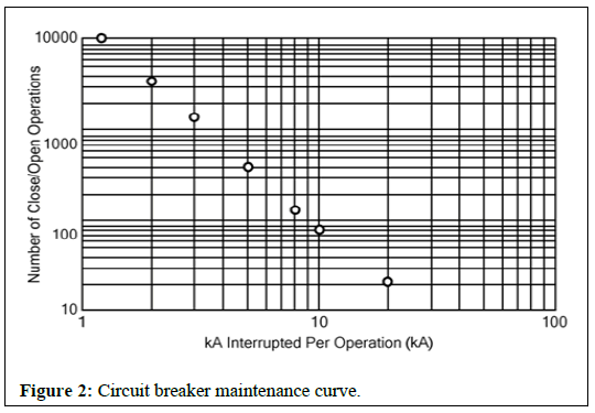
Wear of contacts: Contacts provided in the circuit breaker keep ON-OFF as per the load variance and consumption. OEM of the circuit breaker provide maintenance curve listing the number of closeto- open operations and the interruption current levels. The function of this curve is to predict the breaker contact wear, as the example shows in Figure 2. [9].
Operating time: Mechanical and Electrical operating time interval between the trip and close are being monitored by IED. IED provides status to control units. Total number of operations. Incremental counters for close-to-open operations are implemented to make that information available to the system history.
Spring-loading time: Just after the circuit breaker closes, the time to assert the digital inputs of the IED connected to the breaker loaded spring contact is measured. If this time increases as the number of operations increases, it may predict a problem in the spring-loading mechanism [10].
Trip circuit supervision: Open and close operation of the circuit breaker to be monitored.
Busbar system: Busbar energized position and fault level ratings can monitored.
Data concentrator: Ethernet switches are provided with TCP/IP network, Modbus RTU, Profibus, IEC-61850 to communicate with the upstream controller.
Alarm and trip: Instantaneous overcurrent trip, instantaneous earth fault trip, IDMT over current trip, trip current faulty, circuit breaker lockout, under voltage alarm, inter-trip receive, instantaneous overcurrent trip are provide the monitor through IEDs.
Plug in and plug out: Remote monitoring of plug in and plug out can be monitored through IED (Figure 2).
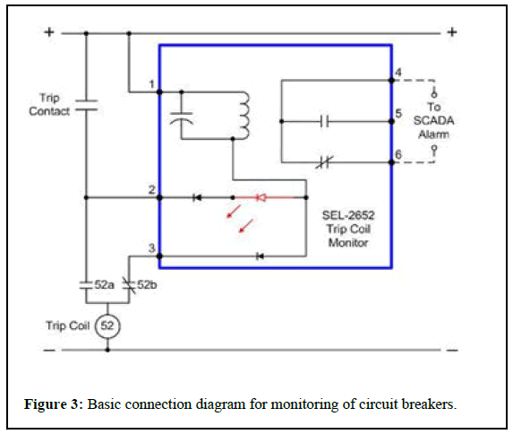
The monitoring functions presented here are performed in a PCM IED with traditional protection PTs and CTs. No additional standalone sensor is necessary for the equipment monitoring system, as shown in the basic connection diagramin (Figure 3).
UPS and battery systems
UPS system consist of rectifier, inverter, bypass, static switch, bypass transformer, isolation transformer, AC/DC converter, DB, batteries and other accessories. UPS system is microprocessor based controlled system logic with intelligent real time fault analyzing, recording and memorization of last 200-300 events is possible. All vital and critical loads are fed from UPS system. Proper operation, maintenance, protection and control of the system is required for smooth running of the system. Proper diagnosis of the system is possible using IED based module at local and remote location. These IEDs have the capacity to monitor with precision for followings [11].
DC voltage positive and negative poles: A difference between the measurements of the poles may indicate a leakage current to ground and possible damage to the charger and/or rectifier.
Rectifier monitoring and fault display: Rectifier ON/OFF position, rectifier input to MCCB, changeover floating for the system, and high rate operation can be control locally and its position can be displayed remotely through IED. Battery breaker position, battery autonomy time remaining, rectifier output current can be displayed locally on LCD monitor of the panel. Rectifier running or stopped position, operation mode, battery operation, imminent discharged battery, DC voltage high and low position can be easily monitored through IED based devices. Failure of the mains power supply, AC input phase under-voltage, charger failure, battery discharging, DC over-voltage, DC under-voltage, rectifier over current, battery overcurrent, DC earth fault, cooling fan failure, battery disconnected or low voltage, Battery MCCB open or trip position will be monitored from local and remote location based on IEC 61850 protocol using IED.
Inverter monitoring and fault display: Inverter supply ON, running status, load on inverter or bypass, available alternative bypass, inverter or bypass synchronized, static switch bypassed can be monitored locally and remotely through IED based devices. Inverter failure, output overvoltage, voltage deviation from the limit voltage, output overload or inverter overcurrent, synchronizing fault, AC earth fault can be monitored both locally and remotely by IED based monitoring [12].
Converter control, measurement, display, monitor, indication and fault display: AC-DC converter ON/OFF, DC output voltage adjustment, load transfer can be controlled from both locally and remote operation based on IED. Incoming AC power supply converter on and off position can also be displayed and monitored both locally and remotely. Failure of converter, output overvoltage, overload, DC earth fault and common failure can be easily monitored by using IED protocols.
Battery loading, charging and discharging: Batter remains in ON position and its charging and discharging depends on load on the system. Charging and discharging shall be monitored continuous for better operation of the system [13].
H2 emission from the battery: H2 keeps emitted in the battery room, therefore, all equipment within the room is classified as Exd type.
DC voltage level: A high or low level of dc voltage can damage the dc battery system or not maintain a proper charging.
Detection of leakage current to ground: If the installation of the dc battery system has a central grounding, it is possible to measure the leakage current to ground and predict problems in the bank battery cabling.
AC ripple in the rectifier: High levels of the ac component of voltage delivered by the rectifier can irreversibly damage the batteries. Additional sensors are not required for this type of monitoring, as shown in the basic connection diagram in Figure 4.
Power transformers
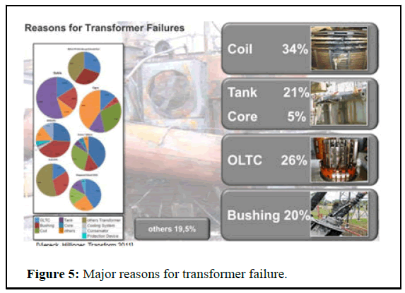
Power transformer is major items. The power transformers shall be suitable for continuous operation. According to the data from various researches and electric power utilities, bushings failures make 5% to 50%, or in average, one quarter of the total number of transformer failures. These failures most commonly cause transformer fires which may result in huge collateral damages of switchyard. 30% of generator step-up transformer failures are caused by a bushing malfunction, and that they also cause 56% of failures accompanied by fire (Figure 5).
DGPT‐2 relay provides protection against pressure, temperature and oil level and is mounted on top cover of transformer. To meet all protection functions of DGPT‐2 relay, manufactured can also provide below protection devices on the transformer:
Pressure Relief Device (PRD) on top cover for Transformer tank protection from excess pressure created due to any abnormality. Oil Temperature Indicator (OTI) and Winding Temperature Indicator (WTI) are provided to monitor oil temperature and winding temperature. OTI and WTI provided with 4 mA‐20 mA output to monitor the temperature from SCMS. Magnetic Oil Level Gauge (MOLG) is provided on transformer tank side wall to monitor the oil level in transformer. Buchholz relay is provided for the protection of transformers from the faultsoccurring inside the transformer.
Therefore, monitoring is essential for providing efficient maintenance as well as for the optimal use of operational capacities. Key Benefits for monitoring the transformer are:
• Remote insight into transformer condition
• Faults can be detected in their infancy
• Transformer load and output can be optimized safely
• Discrete measurement of all fault gases facilitates full diagnostics
• Transformer ageing can be calculated
• Fault type can be classified from results
• Aids condition based and predictive maintenance strategies
On-line DGA device monitors 9 fault gases plus moisture as below:
• Atmospheric gases: Nitrogen and oxygen
• Oxides of carbon: Carbon monoxide and carbon dioxide
• Hydrocarbons: Acetylene, ethylene, methane and ethane
• Hydrogen
There is a range of monitoring sensors and systems designed especially for substation power transformers and IEDs to monitor critical substation transformer assets with a comprehensive transformer thermal model per IEEE C57.91-1995. An automation controller calculates the transformer loading capability rating and mineral oil immersed transformer. PCM IEDs use the data obtained from PTs and CTs in combination with temperature sensors to calculate the top-oil temperature and the winding hot-spot temperature. The substation operator may initiate control action based on a warning or alarm that the transformer is overloaded and in danger of excessive insulation aging or loss-of-life.
The IEDs also monitor the following:
• Cooling bank status which includes fan current, pump current,
current cooling status.
• Efficiency of the forced ventilation system.
• Tap position.
• Ambient temperature.
• Top-oil temperatures.
• Winding hot-spot temperatures.
• Daily loss-of-life rate.
• Accumulated loss-of-life rate.
• Insulation aging acceleration factor.
• Estimated insulation life service.
• Alarms for LTC temperature, top oil limit, winding temp limit, fan
bank supply and pump supply.
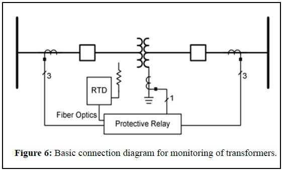
For monitoring the power transformer, the connection of temperature signals to the PCM IED allows correct calculation of thermal modeling, as shown in Figure 6.
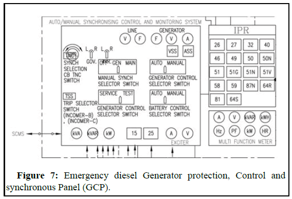
Emergency diesel generator
Diesel power generators provide backup power to main facilities and operations. If there is an emergency or disaster and the main power is shut down, generators can assist with backup, allowing business to continue on as usual Power generators are key to the oil and gas industry.
Genset consider control panel for control and power management system. It is equipped with controller for fast and secure interfacing to other controls and communications systems. These controllers include specifically designed algorithms and logic to start, stop, control, and protect the genset, circuit breaker and the utility, where applicable.
Protection functions are:
• 12 Engine over speed
• 14 Engine under speed
• 25 Synchronization check
• 27 Generator/Mains under voltage relay
• 32 Overload relay
• 32R Reverse power relay
• 46 Phase balance current relay
• 50 Instantaneous overcurrent relay
• 51 AC time overcurrent relay
• 50G Ground fault (measured ground current)
• 55 Generator power factor
• 59 Generator/Mains overvoltage relay
• 78 Mains phase shift/rotation field ROCOF (df/dt)
• 81U Generator/Mains Under frequency relay
• 81O Generator/Mains over frequency relay
Interface and functioning are done with RS-232/485 Modbus RTU slave interface or Ethernet Modbus TCP slave interface (Figure 7).
Discussion
Motor protection and feeder protection
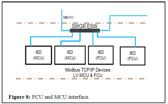
Motor Control Unit (MCU) is used to control, protect and monitor the motor, similarly Feeder Control Unit (FCU) is used to control, protect and monitor the power feeder (Figure 8).
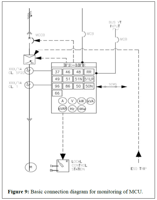
Control, status, alarm, trips is monitored through IEDs. Appropriate Programmable Automation Controllers (PACs) are used to measure the active and reactive power of the motors during operation and receive signals from the angular positioning sensors and the status of the auxiliary contacts of the disconnect switches. These PACs become PCM IEDs and must satisfy the same requirements for reliability as protective relays. They must also meet the same requirements for high availability, environmental ruggedness, and multiple protocols documented in the IEC 61850 communications standard. In this scenario, the PACs are used to monitor the following.
Number of operations: Incremental counters for close to-open operations are implemented in the controllers to make that information available to the system history.
Inactivity time: By monitoring the variation in the number of operations, it is possible for the PAC to calculate the number of days in which the disconnect switch has been inactive. Long periods of inactivity reduce the reliability of the operation.
Switching time for opening and closing: By measuring the time interval between the open or close command and the asserting of the digital inputs of the PAC connected to the disconnect switch status contacts, it is possible to calculate the time of the operation of the switch. Deviations in this value may indicate problems in the drive mechanism.
Average and maximum motor power during operation: The motor power is measured by the PAC through transducers. These samples can be used to calculate the average and maximum values. When these two parameters trend upward, it may indicate mechanical problems in the structure or a failure in the motor.
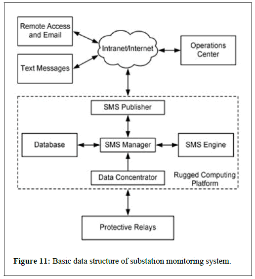
Angular position: The PAC provides this information for evaluation using angular positioning sensors. If the angle recorded exceeds the nominal position, it is indicative of an overload of the mechanical structure and motor. On the other hand, if the angle is smaller, this may indicate a failure in the operation. Figure 5 is a basic connection diagram for the monitoring functions presented above (Figures 9-11).
Premises for the development of the distribution substation monitoring system: As shown previously, investments in substation monitoring systems are essential for creating reliable predictive maintenance; however, standalone systems are complicated and expensive and are only viable for large substations, even though they are becoming essential for smaller distribution substations. Now thatwe understand the structure of the existing SAS network in a substation and the functionalities of monitoring present in PCM IEDs, it is clear that an economically viable monitoring system can be developed by using the network structure and data provided while maintaining the same reliability, regardless of the size of the facility.
Conclusion
Therefore, the requirements for implementation of an SMS that leverages the monitoring capabilities of the SAS are defined as follows. Development of a monitoring system dedicated to managing the maintenance functionally separate from the real-time operation system. Use of PCM IEDs with monitoring functions as a source of data. Use of the communications network infrastructure already in place or provided for the substation as a result of SAS digitalization. Low investment cost, making installation viable in any substation. High reliability and availability of data. The software requirements for SMS implementation are as follows: Integration with an Ethernet network. Remote access to the web via intranet or Internet without the need for additional software and independent of an operational system. Use of a unified database. Graphical analysis with trend lines. Availability of historical data, analysis, and alarms. Values recorded for emission of anomaly alerts or alarms for each variable. Alarms sent through email, voicemail, or text messaging to cell phones. User registration with passwords and hierarchal level access.
References
- Janssen, MC, Apostolov A (2008) IEC 61850 impact on substation design. IEE PES Transm Distribut Confer Exposit 1-7.
- He J, Huang X, Yang Y (2012) Research on smart substation equipment condition monitoring system based on wireless sensor networks. Springer Sci Rev 1: 75-89.
- Hodder S, Hunt R, McGinn D, Kasztenny B, Adamiak M (2008) The advantages of IEC61850 process bus over copper-based protection and control installations. Prot Cont J 29-32.
- Hauck J, Gorg C, Varjopuro R, Ratamaki O, Maes J, et al. (2013) “Maps have an air of authority” potential benefits and challenges of ecosystem service maps at different levels of decision making. Ecosyst Serv 4: 25-32.
- Atanackovic D, McGillis DT, Galiana FD (1998) The application of multi-criteria analysis to substation design. Trans Power Syst 13: 1172-1178.
- Kasztenny B, McGinn D, Ang W, Mao R, Baigent D, et al. (2008) An Architecture and System for IEC 61850 process bus. J Energy 19-29.
- Kumar R, Singh B, Kumar R, Marwaha S (2023) Online identification of underlying causes for multiple and multi-stage power quality disturbances using S-transform. IETE J Res 69: 3739-3749.
[Crossref]
- Mahela OP, Khan B, Haes Alhelou H, Tanwar S (2020) Assessment of power quality in the utility grid integrated with wind energy generation. IET Power Electron 13: 2917-2925.
- He S, Shin HS, Xu S, Tsourdos A (2020) Distributed estimation over a low-cost sensor network: A review of state-of-the-art. Informat Fusion 54: 21-43.
- Sakai RT, Almeida CFM, Rosa LHL, Kagan N, Pereira DDS, et al. (2022) Architecture deployment for application of advanced distribution automation functionalities in smart grids. J Control Autom Electr Syst 33: 219-228.
- Lyttle D, Ford R (1990) A symbolic debugger for real‐time embedded Ada software. Software Pract Exper 20: 499-514.
- Rappaport TS, MacCartney GR, Samimi, MK, Sun S (2015) Wideband millimeter-wave propagation measurements and channel models for future wireless communication system design. IEEE Trans Commun 63: 3029-3056.
- Raingeard E, Freville JC, Grimandi G, Truchaud A (2012) Interest in automating drug distribution-method of comparing technologies available on the French market. The Hospital Pharma Clin 47: 91-105.
Select your language of interest to view the total content in your interested language
Share This Article
Recommended Journals
Open Access Journals
Article Tools
Article Usage
- Total views: 2030
- [From(publication date): 0-2023 - Dec 06, 2025]
- Breakdown by view type
- HTML page views: 1673
- PDF downloads: 357


