Research Article Open Access
FPGA Based Implementation of FFT Processor Using Different Architectures
Debalina Ghosh1*, Depanwita Debnath2 and Dr. Amlan Chakrabarti31Microelectronics and VLSI Design Techno India, Salt Lake Kolkata, India
2Electronics and Communication Engineering Techno India, Salt Lake Kolkata, India
3A.K.Choudhury, School of Information Technology University of Calcutta Kolkata, India
- *Corresponding Author:
- Debalina Ghosh
Microelectronics and VLSI Design Techno India, Salt Lake Kolkata, India
E-mail: debolina1512@gmail.com
Visit for more related articles at International Journal of Advance Innovations, Thoughts & Ideas
Abstract
The Fast Fourier Transform (FFT) is an efficient algorithm for computing the Discrete Fourier Transform (DFT) and requires less number of computations than that of direct evaluation of DFT. It has several applications in signal processing. Because of the complexity of the processing algorithm of FFT, recently various FFT algorithms have been proposed to meet real-time processing requirements and to reduce hardware complexity over the last decades. This is in two directions. One related to the algorithmic point of view and the other based on ASIC architecture. The last one was pushed by VLSI technology evolution. In this work, we present three different architectures of FFT processor to perform 1024 point FFT analysis. The designs have been simulated and its FPGA based implementation has been verified successfully using Xilinx ISE 11.1 tool using VHDL. There are also comparative studies among those architectures. The objective of this work was to get an area & time efficient architecture that could be used as a coprocessor with built in all resources necessary for an embedded DSP application.
Keywords
Fast Fourier Transform, FFT butterfly radix 2 & 4, CORDIC, Sine-Cosine lookup table, Xilinx Core.
Introduction
Audio and communications signal processing are well developed lines massively used now a days in many application lines and products. Since digital communications are quite active fields, the arithmetic complexity of the Discrete Fourier Transform (DFT) algorithm becomes a significant factor with impact in global computational costs. Cooley and Tukey [1] developed the well-known radix-2 Fast Fourier Transform (FFT) algorithm to reduce the computational load of the DFT. The Discrete Fourier Transform (DFT) X(k) of N points is given by
 (1)
(1)
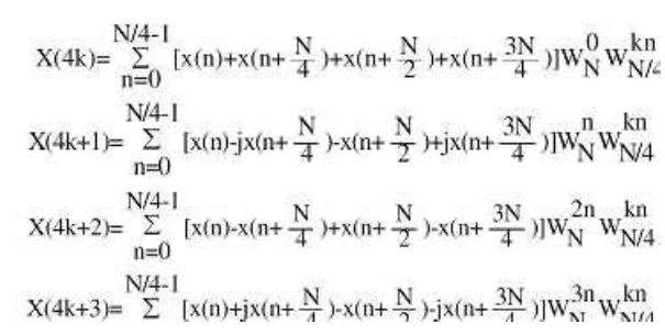
Where the X(k) and x(n) are frequency-domain sequences and time-domain sequence. Instead of the direct implementation of the equation (1), the FFT algorithm factorizes a large point DFT recursively into many small point DFT in order to reduce the overall operations. There are two well-known types of decompositions called Decimation in Time (DIT) and Decimation In Frequency (DIF) FFT. The only difference between these two algorithms is that, DIT starts with bit reverse order input and generates normal order output. Nevertheless DIF starts with normal order input and generates bit reverse order output. Throughout this paper DIF algorithm is used. The conventional method of Fast Fourier Transform FFT calculation involves N2complex multiplications and N(N-1) complex additions. The radix-2 Cooley-Tukey algorithm performs the same computation involving (N/2)log2N complex multiplications and (N)log2N complex additions. But it is more efficient computationally to employ a radix-4 FFT algorithm other than radix -2 logarithms. The radix-4 decimation-in frequency DFT is given by
 (2)
(2)
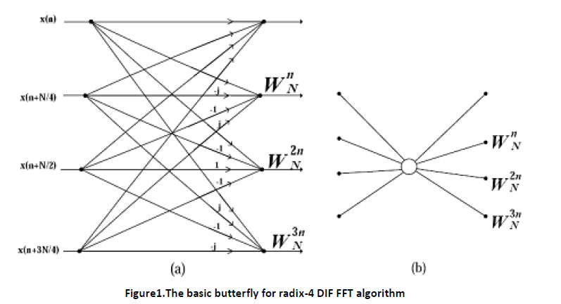
Note that the input to each N/4-pointDFT is a linear combination of four signal samples scaled by a twiddle factor. This procedure is repeated v times, where v = log4N. The complete butterfly operation for Radix-4 DIF is shown in figure 1 (a) and in a more compact form in figure 1(b).
In this paper, we present radix-4 FFT processor using different architectures that allows any size points to transform, fixed point arithmetic, pipeline structure and parameterized data format. The synthesis performance results of the proposed model will be compared with the Xilinx FFT cores and the advantages and disadvantages of each realization will be discussed. The next section describes the architectural design of the FFT structure. Section 3, shows implementation and design results. Finally, conclusions are exposed in section4.
Proposed methodology
1024 point FFT processors are designed using three different architectures. In one of the architecture Twiddle factors are generated using CORDIC (Coordinate Rotation Digital Compute) algorithm, in another one through Sine/Cosine Look up table it is generated. Xilinx Logicore FFT processor is also used as useful architecture. All are designed in FPGA through VHDL.
A. Design of FFT Processor using CORDIC algorithm
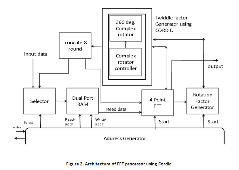
The design flow of FFT Processor using CORDIC is shown in figure 2.The selector block is nothing but a memory path buffer which compute respective memory of input samples. When Active signal is asserted and there are some input data, the address generator block assigns a memory position for each input sample. Now when Dual port Ram gets write Address signal from address generator block, it saves both memory path along with respective input samples. The 4 point FFT block has butterfly unit within it.
When a start signal is asserted, at the same time, both to 4 Point FFT and Rotation factor generator block, the FFT block sends a signal to CORDIC block for computing necessary twiddle factors consisting of sine-cosine terms. This block is controlled by Rotation factor generator block. In truncate & round block, remapping of memory path and twiddle factors are held and fed back to FFT block. Now when address generator block sends read address signal to DRAM, it sends stored input data samples along with memory path in FFT block. Finally this twiddle factors are applied to the output of the butterflies, and a bit reverse scramble is done. in the implementation of FFT, it is noticed that remapping of the memory is necessary. In the implementation of DIF the remapping is made from the exit of FFT. However that remapping can be made in a simple way. For instance, for the FFT radix-4 DIF, the entrance has to be written in the addresses of memory 0, 1, 2, 3, 4, 5, 6 and 7. After having processed a scrambling phases, it has to write in 0, 4, 2, 6, 1, 5, 3 and 7. That scrambling follows a much defined order. As 1024 point FFT processor is designed, the whole module of architecture is used for 5 times. The formula behind this is
 (3)
(3)
B. Design of FFT Processor using Sine-Cosine lookup table algorithm
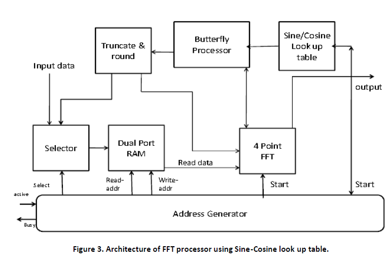
The design flow of FFT Processor using Sine-Cosine look up table is shown in figure 3. The design flow is quite similar with the processor designed in figure3.Only the difference is that sine-cosine look up table is here used to compute the value of twiddle factors, which are previously stored in a RAM.
C . Design of FFT Processor using Xilinx Core
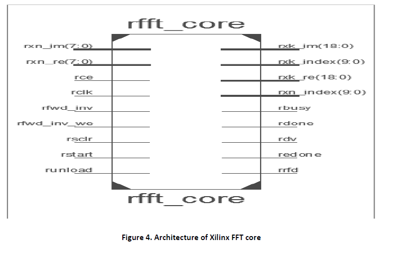
In this section Xilinx FFT core is used during to compute 1024 point FFT transform. The Xilinx FFT core offers a number of different architectures and also supports several arithmetic computations. The architecture of Core FFT is shown in figure 4.During the implementation of FFT Core many initialization was made. Such as Radix-4, Burst I/O architecture is used because in this solution the FFT core uses one radix-4 butterfly processing engine and has two processes. One process is loading and/or unloading the data. The second process is calculating the transform. Data I/O and processing are not simultaneous. When the FFT is started, the data is loaded in. After a full frame has been loaded, the core will compute the FFT. When the computation has finished, the data can now be unloaded. During the calculation process, data loading and unloading cannot take place. The data loading and unloading processes can be overlapped if the data is unloaded in digit reversed order [3].
The inputs are provided as 8-bits fixed-point data type. Coefficients are internally saved in the core and are also represented as 8-bit fixed-point data. We apply full-precision unscaled arithmetic, which takes into account the number of bit growth at each stage.In order to determine the necessary bits for correct representing the outputs, the core applied the formula [3]:
Output data width = input data width + log2 (transform length)+ 1 (4)
This approach will make sure that almost no data will be lost during the computation.
Results, discussion and design summary
A. Results and Discussion
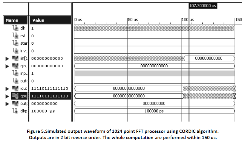
We have simulated the three mentioned FFT processor architecture blocks using Xilinx Isim 11.1.In these concerned designs we have used fixed point format to truncate &round of the values. Figure 5 shows the test bench waveform of 1024 point FFT processor using CORDIC algorithm, which is tested for real data inputs. First, data loading process is done, then after computation output data unloading is done. In Output both real & imaginary terms are get.
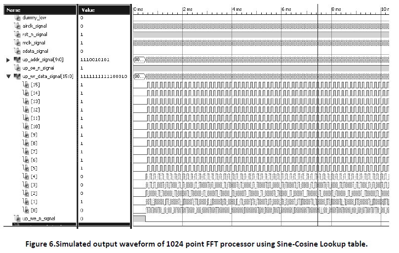
In Figure 6 the test bench waveform of 1024 point FFT processor using Sine-Cosine Lookup table is shown. Here the real and imaginary parts of output data are concatenated for real input data samples. Here FFT starts around 15ms and finishes soon. The execution period is 206us (= 10,300/50MHz). That means 1024-point FFT is computed only in 10k cycles.
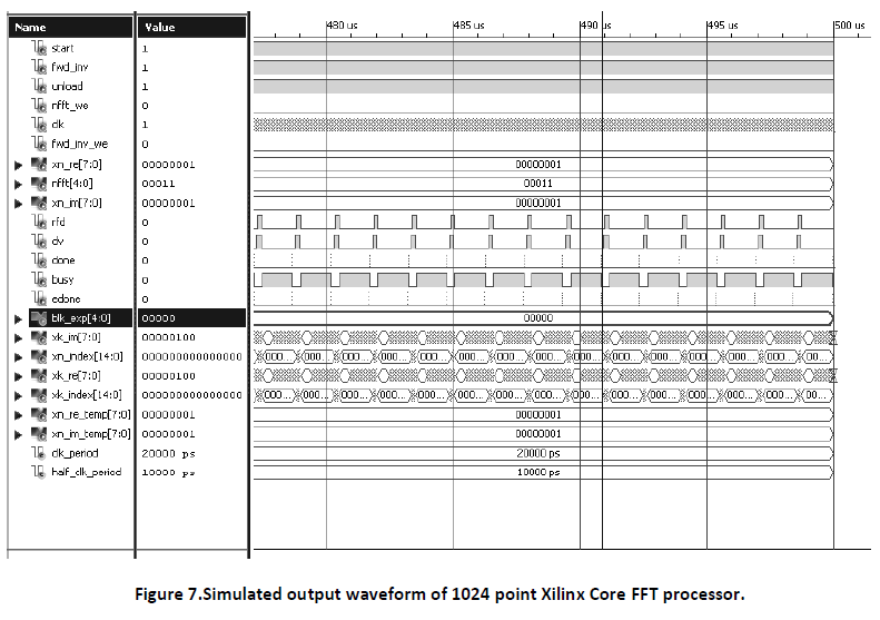
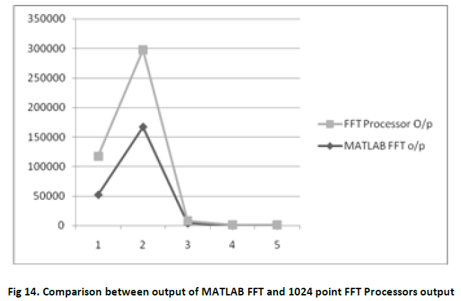
Figure 7 shows the test bench waveform of Xilinx Core 1024 point FFT Processor. The latency of this processor is only 50 us. Here the computation is performed for real and imaginary data inputs. Input data loading and Output data unloading is overlapped due to design constraints. Table 1 shows the comparison between output of MATLAB 1024 point FFT and 1024 point FFT processor for the same input data.
B . Design Summary
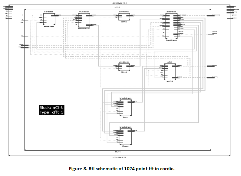
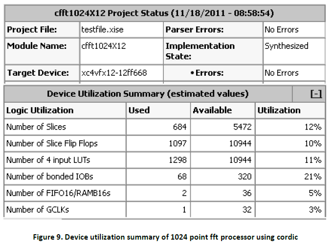
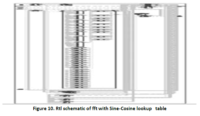
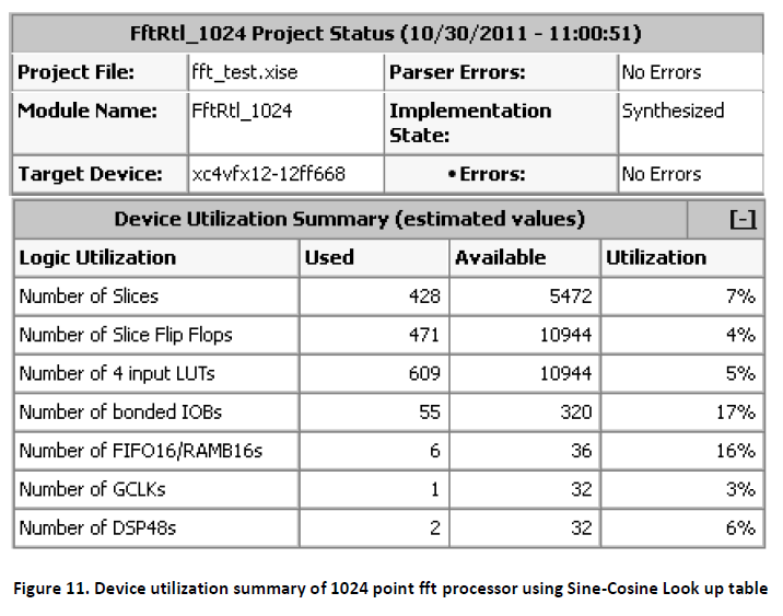
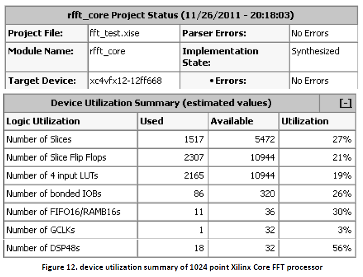
Design summary is a report which allows designer to view the information like targeted device, the number of errors and warning, device utilization & design goal. We have implemented our design in FPGA family Virtex4(4vfx12ff668speed grade -12).Also the RTL schematic of the three mentioned FFT processor blocks are shown. These RTL schematics are basic logical representation of the circuit in terms of logic primitives which are generated when the design become correct in simulation and synthesis level. Figure 8 & figure 9 shows the RTL schematic &device utilization summary of 1024 point FFT processor using CORDIC algorithm. Figure 10 & Figure 11 shows the RTL schematic &device utilization summary of 1024 point FFT processor using Sine-Cosine lookup table. Figure 12 shows the device utilization summary of 1024 point Xilinx Core FFT processor.
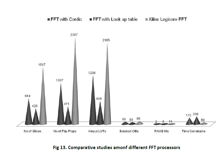
A comparative study of device utilization summary and computation time, among the three mentioned FFT Processors are done. This is shown in figure 13.
From Figure 13 it is realizable that Xilinx Core FFT takes much less computation time than other two FFT processors. Also it consumes more device than others. So, in processing and computation point of view FFT Processor using Cordic algorithm, is little more sufficient compare to other two FFT Processors.
Figure 14 shows the comparison between output of MATLAB FFT and 1024 point FFT Processors output. From figure 14 it is realizable that for small input data, there is variation between outputs of MATLAB FFT and FFT Processor. But as input data increases, the variation between outputs decreases.
Summary and conclusion
This paper presents 1024 point FFT processor using three different architectures which are portable among different EDA tools and technology independent. The whole designs are implemented in VHDL through Xilinx ISE11.1The performance of the designs that is using CORDIC algorithm, and using Sine-Cosine look up table, have been compared with the commercial cores provided by Xilinx . This core was configured with the closet characteristics to our designs in order to make the results comparable. The performance of our designs present better results in terms of physical resources demanded but the throughput is poorer when compared with the IP commercial implementations. Along with these performance results come other considerations which need to be evaluated to select the best approach depending on system requirements like easy implementation, costs and performance. The generation of a design from an IP commercial core is as easy as to press a button but the design has not been controlled because they are provided as a black box. They offer a variety of features and functionalities to be configured and supposedly their implementations are optimized for a subset of their devices, giving the best performance for them but they lack portability. Our FFT designs have been integrated as part of a Speech Recognition System together with the other parts of the system such as end point detection, MFCC feature extraction. In this case the physical resources performance in order to have full implementation of the system in the same FPGA is more important than other criteria used. The designs are currently under final FPGA realization and will be reported in the future.
References
- Young-jin Moon, Young-il Kim “A Mixed-Radix 4-2 Butterfly with Simple Bit Revering for Ordering the Output sequences,” ICA0T2006 vol. 4, pp. 1772–1774, February 2006.
- A. Sreir.sr, C. Ka-a-Terki, H. Mshrez, S. Negus, “A Flexible Hish Perfomance Serial Radix-2 fft Butterfly Arithmetic unit” IEEE Transl. J. Magn. Japan, vol. 2, pp. 26-29, August 1987 [Digests 9th Annual Conf. Magnetics Japan, p. 301, 1982].
- Xilinx Logi Core FFT Processor guide.pdf.
- Chung-Ping Hung, Sau-Gee Chen and Kun-Lung Chen , “Design Of An Efficient Variable-length FFT Processor”, ISCAS 2004,vol -4,pp.833-836.
- C. Gonzalez-Concejero, V. Rodellar, A. Alvarez-Marquina, E. Martinez de Icaya and P.Gomez-Vilda, “ An FFT/IFFT design versus Altera and Xilinx cores”, 2008 International Conference on Reconfigurable Computing and FPGAs,IEEE.Vol -8,pp.337-342.
- D. B. Williams, V. K. Mandisetti, The Digital Processing Handbook, CRC press & IEEE press,1998. page 7-32 [7] Y. Ma, “An Effective Memory Addressing Scheme for FFT Processors,” IEEE Trans. on Signal Processing, Vol. 47 Issue: 3, pp. 907-911, Mar. 1999.
- W. B. Jervis and E. C. Ifeachor, Digital Signal Processing: A Practical Approach. Reading, MA: Addison-Wesley, 1993.
- S. G. Johnson and M. Frigo, A modified split-radix FFT with fewer arithmetic operations, IEEE Transactions on Signal Processing, 2007, pp. 111-119.
- L. G. Johnson, “Conflict Free Memory Addressing for Dedicated FFT Hardware,” IEEE Trans. on Circuit and System-II Analog and Digital Signal Processing, Vol. 39 No.5, pp.312-316, May 1992.
- Earl e. Swartzlander, Jr., senior member, IEEE, Wendell k.W. young, member, IEEE, and Saul j. Joseph, member IEEE, “A Radix 4 Delay Commutator for Fast Fourier Transform Processor Implementation” , IEEE journal of solid-state circuits, vol. sc-19, no. 5, october 1984.
Relevant Topics
Recommended Journals
Article Tools
Article Usage
- Total views: 22821
- [From(publication date):
January-2012 - Jul 17, 2024] - Breakdown by view type
- HTML page views : 18069
- PDF downloads : 4752

