Like us on:
Fathi Elldakli*, Mohamed S1 and Mehdi SH2
Received Date: July 24, 2017; Accepted Date: July 28, 2017; Published Date: August 07, 2017
Citation: Elldakli F, Mohamed S, Mehdi SH (2017) Enhanced Gas Lift Valve Performance for Sharp Edged Seat using Larger Ball Sizes. Oil Gas Res 3: 143. doi: 10.4172/2472-0518.1000143
Copyright: © 2017 Elldakli F, et al. This is an open-access article distributed under the terms of the Creative Commons Attribution License, which permits unrestricted use, distribution, and reproduction in any medium, provided the original author and source are credited.
Visit for more related articles at Oil & Gas Research
Theoretically, each Sharp Edged Seat has fully open stem travel based on the port and ball diameters. Gas lift valve 1.5” has 6 different port diameters (3/16”, ¼”, 5/16”, 3/8”, 7/16” and ½”). For each port the ball diameter is usually larger than the port diameter by 1/16”. Laboratory testing for sharp edged seats showed that the actual flow area is less than theoretically calculated area resulting from the bellows stacking before the stem reaches the fully open. Consequently, the valve stem restricts the flow and the flow rate through the valve declines. The purpose of this work is to examine the possibility of improving the efficiency of the gas lift valve by using larger ball size than conventionally used. For each port, different ball sizes were tested at different stem positions for the same condition (Injection pressure & Temperature). Results obtained from benchmark test displayed increasing in the flow rate as the ball size increases at the same stem travel.
Temperature; Gas; Reservoir; Injection
Oil wells producing naturally do not need lift method. However, if the reservoir pressure failed below the economic pressure, the flow rate will be decreased. In order to maintain the production, an artificial lift method should be applied. One of the most important artificial lift methods is gas-lift. The goal of gas lift is to reduce the flowing gradient by injection gas to lower the fluid density. Low column gradient create higher drawdown forces the fluid out of the wellbore. The reservoir pressure is then able to carry the oil to the surface. The volume of gas to be injected changes based on well situation. If we inject more than or less than the required amount of injected gas, the production will be less than optimum production. The gas lift valve is the most important part of gas lift system. Its control the flow rates by closing and opening when it required. There are many kinds of gas lift valves developed; the pressure opened type is the most successful one [1]. The valve used in this study is a single element gas lift valve which classified as pressure injection operated valve. The main parts of this valve are: gas dome which filled with high pressure gas (usually nitrogen); metal bellows provides the movement of the valve stem; and the port which allow the injected gas to flow through the valve. The valve stem tip moves to open or close the valve based on pressure condition. The 1.5” OD valve has 6 different port sizes (3/16”, ¼”, 5/16”, 3/8”, 7/16” and ½”). For each port stem tip (ball) is 1/16” larger than the port diameter.
Flow area
The open forces created by injected gas push the ball to move out of the seat; the valve opens and the flow area increases. At any valve stem position, the generated flow area is the lateral area of the frustum of aright circular cone, Figure 1, Kulkarni [2] stated the valve stem travel, the flow area gradually increases, and at some point, when the stem travel reach fully open, actual flow area will get the size of the valve port area. Experimental data for sharp edged seats Shahri, Winkler [3,4] showed that the flow area through a gas lift valve linearly increases with valve stem travel until the maximum area equivalent to port area is reached. During operation, because the axial loading, the bellows convolutions is compressed and come to lie on each other. Therefore, the bellows stacking before the stem travel the required distance to reach the fully open. The ball, therefore, will restrict the rate of gas injection through the valve. The size of the port is another factor that will dictate the amount of travel required. Evidently, large ports require more stem travel than small ports. The theoretical minimum stem travel depends on port and ball diameters and can be calculated using Equation.1. Table 1 shows the amount of travel required to get a flow passage equivelent to that of the port. It should be noted that although this travel would allow a flow area equivelent to the port area, the stem is still a major restriction in the flow path.
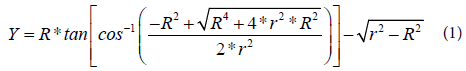
Where, R: Port radius and r: Ball radius

Figure 1: Effective flow area.
| Port, inch | Ball size, inch | Minimum stem travel for fully open, inch |
|---|---|---|
| 1/4 | 5/16 | 0.1003 |
| 5/16 | 3/8 | 0.1302 |
| 3/8 | 7/16 | 0.1610 |
Table 1: Minimum stem travel for sharp edged seat ( Ball size=Port size+1/16 inch).
The aim of this work is to study the effect of the ball size on the flow behavior of gas lift valve with sharp edged seat. On the other words, how the ball size can help reduce the required stem travel for fully open. The minimum stem travel for each port with different balls sizes was calculated using the same equation 1 with different ball sizes. The results are compared with minimum stem travel when the ball is only 1/16” larger than the port. Table 2 illustrates that the stem travel required for each port with larger balls is less with the conventional one.
| Port, inch | Ball size, inch | Minimum stem travel for fully open, inch |
|---|---|---|
| 1/4 | 5/16 | 0.1003 |
| 3/8 | 0.0884 | |
| 7/16 | 0.0822 | |
| 1/2 | 0.0783 | |
| 9/16 | 0.0756 | |
| 5/16 | 3/8 | 0.1302 |
| 7/16 | 0.1151 | |
| 1/2 | 0.1069 | |
| 9/16 | 0.1016 | |
| 3/8 | 7/16 | 0.1610 |
| 1/2 | 0.1428 | |
| 9/16 | 0.1326 |
Table 2: Minimum stem travel for sharp edged seat using larger ball size for each port.
Benchmark valve
Because the valve does not fully open immediately and the area increases gradually, the valve was tested using benchmark valve to study the flow behavior at different stem positions. The benchmark valve has the same dimensions of the actual gas-lift valve. It has the same actual valve body, stem OD, ball/seat assembly, etc. However, there is no bellows or dome section, and we can adjust the stem position at different positions [4]. A schematic of actual and benchmark gas lift valves are illustrated in Figures 2 and 3 respectively.

Figure 2: Schematic of injection pressure operated (IPO) GLV.

Figure 3: The benchmark valve components (Winkler 1987).
This paper deals with Experimental Lab Study and detailed analysis of approximately 60 Benchmark tests as presented at Table 3. These tests are simply discharging a certain volume of gas at a certain time till the upstream pressure reaches the final downstream pressure which is ambient pressure. Three different ports (¼”, 5/16” and 3/8”) were tested at 25%, 50%, 75%, 100%, 125% and 150% of fully open with different ball sizes for each port. Table 3 explains the different tests. At each ball position the gas was injected through the valve and the data was gathered digitally using data-acquisition system (DAS).
| Ball position of fully open | |||||||
|---|---|---|---|---|---|---|---|
| Port, inch | Ball size, inch | 25% | 50% | 75% | 100% | 125% | 150% |
| 1/4 | 5/16 | X | X | X | X | X | X |
| 3/8 | X | X | X | X | X | X | |
| 7/16 | X | X | X | X | X | X | |
| 1/2 | X | X | X | X | X | X | |
| 9/16 | X | X | X | X | X | X | |
| 5/16 | 3/8 | X | X | X | X | X | X |
| 7/16 | X | X | X | X | X | X | |
| 1/2 | X | X | X | X | X | X | |
| 9/16 | X | X | X | X | X | X | |
| 3/8 | 7/16 | X | X | X | X | X | X |
| 1/2 | X | X | X | X | X | X | |
| 9/16 | X | X | X | X | X | X | |
Table 3: Benchmark valve tests (different ball sizes at various ball positions).
Theoretical calculation of minimum stem travel required to create equivalent port area showed that as the ball size getting larger, the minimum stem travel is less. By using the new stem travel, the calculated area from tests at different stem position is larger than conventional one. Figures 4-6 show that as the ball size increases the flow area is larger at the same stem travel. Calculating gas flow rate at new stem positions is another factor to see the effect of the ball size which we can detect from (Figures 7-9). The experiment results showed that larger ball size provided higher flow rate at same stem travel for all ball positions. There are two main reasons for the effect of the ball size. The first reason is the contact point between the large ball and the top of the seat is higher. So less ball movement well generate the same flow area with smaller ball. The second reason is the Coanda Effect. When the gas stream flows past the ball, some of the gas follows the contour of the ball and only leaves after it moves a significant distance along the surface of the ball, In effect, the ball pulling the gas around its surface, Figure 10 shows schematic diagram for Coanda Effect. Because the ball was fixed to the valve body, it cannot move resulting in direction the gas stream toward the port which increases the flow rate. In all cases it was found that the larger the port size, the greater was the efficiency.

Figure 4: Effect of ball size on flow area (Port ¼”).

Figure 5: Effect of ball size on flow rate (Port 1/4”).

Figure 6: Effect of ball size on flow area (port 5/16 inch).

Figure 7: Effect of ball size on flow rate (Port 5/16”).

Figure 8: Effect of ball size on flow area (Port 3/8”).

Figure 9: Effect of ball size on flow rate (Port 3/8”).

Figure 10: Coanda effect.
- As the ball size increases, the stem travel required to generate fully open position decreases because the ball contacts the seat at higher position.
- At the same stem travel, using larger ball size provides a higher flow rate.
- Coandda effect is another reason to justify the improved of flow rate using larger ball size.
Make the best use of Scientific Research and information from our 700 + peer reviewed, Open Access Journals