Electromagnetic Reciprocating Engine White Paper
Received: 01-Jun-2015 / Accepted Date: 08-Jul-2015 / Published Date: 10-Jul-2015 DOI: 10.4172/2090-5009.1000118
Abstract
Business has been looking to end its dependency on Oil. Oil supplies are dwindling, the demand is increasing along with the cost. The Electromagnetic Reciprocating Engine, for which Sekou holds the patent, can replace the Combustion Engine; it does not use any fossil fuels. The Electromagnetic Reciprocating Engine can replace the Combustion Engine in any vehicle, eliminating the fuel cost. The Electromagnetic Reciprocating Engine can replace the Combustion Engine in an engine-generator, creating green renewable electricity. The Electromagnetic Reciprocating Engine has a low operating cost with an 110,000 h or 12 year maintenance cycle. The Electromagnetic Reciprocating Engine can end the need for fossil fuels in transportation and electricity production for homes and businesses.
Keywords: Electromagnetic reciprocating engine; Fossil fuels; Magnetic energy
17773Introduction
Fossil Fuels are what powers transportation and electricity around the World. The byproducts of Fossil Fuels are changing the climate. The cost and supply of Fossil Fuels affects businesses bottom line. What can businesses do to decrease the Fossil Fuels demands, decrease operating cost, help the environment and increase profits? There is a new engine that does not require Fossil Fuels, does not harm the environment, and has low maintenance cost. The technical name is the Electromagnetic Reciprocating Engine. It is a Mechanical Renewable Energy System. There is a new engine that does not require Fossil Fuels, does not harm the environment, and has low maintenance cost. The technical name is the Electromagnetic Reciprocating Engine. It is a Mechanical Renewable Energy System.
Mechanical Energy Systems are how the World produces electricity and transportation. Most of the energy is provided by some type of mechanical energy system with different fuel sources. The main fuel source is some type of Fossil Fuels. Renewable Energy or Sustainable Systems, are a source of energy that can be replaced, it’s an endless circle of energy. Renewable Energy is an energy source that does not harm the environment. To date solar panels and fuel cells are the only energy systems that do not turn a mechanical system.
Mechanical Energy Systems:
• Natural Gas for electricity – heat – turns a mechanical system
• Natural Gas for transportation – pressure – turns a mechanical system
• Oil – heat – turns a mechanical system
• Oil – pressure – turns a mechanical system
• Nuclear Fusion – heat – turns a mechanical system
• Renewable Energy:
• Biofuels – pressure – turns a mechanical system
• Biomass – heat – turns a mechanical system
• Wind – turns a mechanical systems
• Solar to steam – heat – turns a mechanical system
• Geothermal – heat – turns a mechanical system
• Hydro – pressure – turns a mechanical system
• Magnetic Energy – pressure – turns a mechanical system
The secret of the Electromagnetic Reciprocating Engine lies in the four years of research and experiments in “Can magnetic force push down on a piston” which culminated into the development of the Magnetic Chamber. This research concluded with an US Patent #7,557,473. The Electromagnetic Reciprocating Engine uses Magnetic Energy to turn a crankshaft. The Magnetic Energy is used to move the Magnetic Chamber in a linear motion, that motion is converted into a rotating motion by a crankshaft. That crankshaft converts that motion into horsepower and torque with efficiency by using haft strokes. The crankshaft is used to turn an alternator which produces the electricity for the electromagnets in the Magnetic Chamber. The Magnetic Energy is produced by the electromagnets which are powered by electricity from an attached alternator. The crankshaft can be connected to a transmission for vehicles or a generator to produce electricity.
The Electromagnetic Reciprocating Engine:
• NO Fossil Fuels
• NO effect on the climate – totally green
• 97% more HP then the Combustion Engine
• Low Operating Cost – 110,000 h or 12 years
• Placed in any vehicle – cars to large trucks
• Renewable Electricity 2 kW to 9 MW per engine
• Changes the understanding of physics
In a world of dramatic, and at times, severe climatic change due to the overproduction of carbon dioxide through the burning of Fossil Fuels; and an over dependence on Oil, which has made the world subservient to a few countries, we face an almost insurmountable problem that screams for a solution.
The Electromagnetic Reciprocating Engine is environmentally friendly solution.
• NO Fossil Fuels
• NO Emissions
• NO Oil for lubrication, Magnetic Bearings
Problems
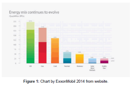
The unstable cost of Fossil Fuels i.e., Oil (Gasoline, Diesel), Natural Gas and other fuel sources for transportation and electricity production has created uncertainty (Figure 1).
Expanding energy will require trillions of dollars in investment. The IEA estimates that meeting the world’s energy needs will require expenditures on the energy-supply infrastructure of approximately $1.6 trillion per year on average through 2035. About half of the investments relate to projected Oil and Natural Gas needs, while approximately 45 percent relate to expected power generation requirements.
Oil dependency
The World’s Oil supply is a limited resource. Different organizations have different durations, but they all agree that Oil will end. In 2002 ExxonMobil charted that Oil should end around 2040. New Oil supplies have been found since then but Oil will end. Oil, Fossil Fuel, remains the top global energy source and the fuel of choice for transportation. Demand for Oil is projected to rise by approximately 25 percent through 2040, led by increased commercial transportation activity. A growing share of this demand will be met by sources such as deep-water, Oil sands and tight Oil, which are increasing as a result of advances in technology.
The International Energy Agency’s (IEA) World Energy Outlook 2010 projected world Oil production to increase through 2035, with depleting conventional Oil being replaced by fields yet to be found and fields yet to be developed.
To avoid the serious social and economic implications a global decline in Oil production could entail, the 2005 Hirsch report emphasized the need to find alternatives, at least ten to twenty years before the peak, and to phase out the use of petroleum over that time. This was similar to a plan proposed for Sweden that same year. Such mitigation could include energy conservation, fuel substitution, and the use of unconventional Oil. Because mitigation can reduce the use of traditional petroleum sources, it can also affect the timing of peak Oil and the shape of the Hubbert curve. The less we use, the longer it will last.
The US Military has come to the conclusion that the energy supply is vital for security, energy security. The DOD has completed a plan in June 2011, Operational Energy Strategy that outlines three ways to increase energy security: 1) reduces demand for fuel, 2) diversify energy supply and 3) incorporating these considerations into building the future force.
The Electromagnetic Reciprocating Engine will end the need of Oil in transportation and power generation.
Oil expenses
The cost of fuel changes over time and affects the operating cost of any organization. The Electromagnetic Reciprocating Engine will end fuel cost.
FedEx is an example of a company that would have saved $12 billion in three years of operations (Tables 1 and 2).
| FedEx Fuel Expenses | |||
|---|---|---|---|
| 2012 | 2011 | 2010 | |
| Expense (in millions) | 4,956 | 4,151 | 3,106 |
| Percent of Revenue | 11.6 | 10.6 | 8.9 |
Table 1: The United State Government would have saved $2.5 billion in two years operations.
| United State Government Fuel Expenses | ||
|---|---|---|
| Fuel Type | 2010 | 2011 |
| Gasoline | 939,024,355 | 1,046,695,356 |
| Diesel | 213,360,941 | 248,901,198 |
| Biodiesel (B100) | 592 | 211,104 |
| Biodiesel (B20) | 19,255,051 | 24,822,915 |
| CNG | 1,178,322 | 1,116,769 |
| Electric | 387,128 | 468,852 |
| Ethanol/E-85 | 26,392,840 | 38,496,662 |
| LNG | 570 | 648 |
| LPG | 292,968 | 477,127 |
| Hydrogen | 20,509 | 17,513 |
| Grand Total | 1,199,913,276 | 1,361,208,134 |
Table 2: Federal Fleet Report 2011 table 5(2) trend: fuel cost by fuel type by year.
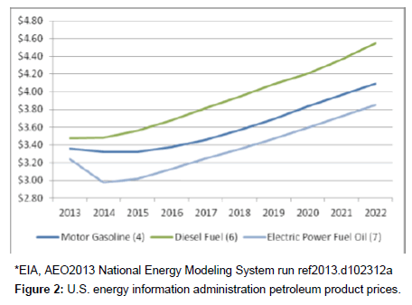
Oil cost projections
U.S. energy information administration petroleum product prices (Figure 2).
Natural gas dependency
Natural Gas, Fossil Fuel, will contribute the biggest growth in energy supplies. Natural Gas is affordable, widely available, extremely versatile, and emits up to 60 percent less carbon dioxide than coal when used for power generation. With abundant resources unlocked by continuing technology advances, Natural Gas is expected to become more important in the global energy mix, accounting for more than 25 percent of global energy needs by 2040, as Natural Gas demand rises by about 65 percent.
Natural Gas is primarily used for producing electricity but can replace Oil in transportation. New ways of extracting Natural Gas has increased the supplies. Just like Oil, there are limits on the supply of Natural Gas.
The Electromagnetic Reciprocating Engine will end the need of Natural Gas in transportation and power generation.
Other fuels dependency
Nuclear: Nuclear energy will see solid growth. While some countries scaled back their nuclear expansion plans in the wake of the 2011 Fukushima incident in Japan, many other countries are expected to expand the use of this energy source to meet electricity needs while reducing emissions. Growth will be led by the Asia Pacific region, where nuclear output is projected to rise from 3 percent of total energy in 2010 to close to 9 percent by 2040. The Electromagnetic Reciprocating Engine will end the need of Nuclear power generation.
Standard renewables: Renewable energy supplies – including traditional biomass, hydro and geothermal as well as wind, solar and biofuels – will grow by close to 60 percent, led by increases in hydro, wind and solar. Wind, solar and biofuels are likely to make up about 4 percent of energy supplies in 2040, up from 1 percent in 2010. We foresee wind and solar providing about 10 percent of electricity generated in 2040, up from about 2 percent in 2010.
The Electromagnetic Reciprocating Engine will end the need of Standard Renewables in transportation and power generation.
Climate change
What is Climate Change? According to Wikipedia “Climate Change is a significant and lasting change in the statistical distribution of weather patterns over periods ranging from decades to millions of years”. It may be a change in average weather conditions, or in the distribution of weather around the average conditions (i.e., more or fewer extreme weather events). Climate Change is caused by factors that include oceanic processes (such as oceanic circulation), biotic processes, variations in solar radiation received by Earth, plate tectonics and volcanic eruptions, and human-induced alterations of the natural world; these latter effects are currently causing global warming, and “Climate Change” is often used to describe human-specific impacts.”
The EPA states “Over the past century, human activities have released large amounts of carbon dioxide and other greenhouse gases into the atmosphere. The majority of greenhouse gases come from burning Fossil Fuels to produce energy, although deforestation, industrial processes, and some agricultural practices also emit gases into the atmosphere.”
The burning of Fossil Fuels is the primarily used in two industries, Transportation and Power. The Transportation Industry uses Fossil Fuel in the Combustion Engine in vehicles of all sizes. The Power Industry burns Fossil Fuel in large power plants to turn turbines to produce electricity.
The Electromagnetic Reciprocating Engine produces NO carbon dioxide and other harmful greenhouse gases. Carbon Dioxide is one of the causes of the World’s Climate Changed. With most of the carbon dioxide and other greenhouse gases is from the Fossil Fuel combustion and the second larges from the Combustion Engine.
The Electromagnetic Reciprocating Engine can end the use of Fossil Fuels in the Transportation Industry and Power Industry.
Greenclean Energy
The Electromagnetic Reciprocating Engine is a Green and Clean Energy source which uses Magnetic Energy to turn a crankshaft. That crankshaft is used to turn a generator for renewable electricity or turn a transmission in a vehicle of unlimited range.
The Electromagnetic Reciprocating Engine operates by taking electricity from a battery, convert it to Magnetic Energy using electromagnets, and convert that kinetic energy to Mechanical Energy using the crankshaft. The electricity, stored in a battery, is the primary energy source. The energy is send to electromagnets which turn that electricity into Magnetic Energy, magnetic force. The magnetic force is used to turn a crankshaft. The crankshaft will increase the energy using Mechanical Advantage and send that Mechanical Energy to two places: [1]. It will send part of the energy as electricity, by turning an alternator, back to the battery and electromagnets [2]. It will send the remaining energy, Mechanical Energy, using a shaft which can turn ether a generator or a transmission.
The Electromagnetic Reciprocating Engine can produce various amounts of horsepower and torque. The horsepower is controlled by two things, the size of the crankshaft which dictates the amount of magnetic force needed from the electromagnets and the number of Magnetic Chambers.
The Electromagnetic Reciprocating Engine is a Perpetual Motion Engine, a Mechanical Renewable Energy System.
Perpetual motion engine
The Perpetual Motion Engine is an engine that takes primary energy from an outside source, converts that energy to Mechanical Energy, amplifies that Mechanical Energy, converts some of that Mechanical Energy to electricity and return it to the primary energy source and the remaining Mechanical Energy is open to be used in anyway.
Perpetual Motion Machine, a device that will run forever without any outside source of energy. Such a machine cannot exist, because it would violate the principle of conservation of energy, which states that energy can neither be created nor destroyed. Some energy would always be wasted (although not destroyed) through friction and so the supply of useful energy – needed to run the machine – would eventually be depleted. Since the machine could not create new energy, it would stop running.
The current understanding has changed when it comes to the Electromagnetic Reciprocating Engine. The principle of conservation of energy is not being violated, energy is not being created. The primary energy is electricity stored in batteries. The electricity is sent to electromagnets which converts the electricity to Magnetic Energy. The Magnetic Energy is use to turn a crankshaft in the Magnetic Chamber which converts that energy into Mechanical Energy. There are three advantages in the Electromagnetic Reciprocating Engine when converting energy:
1. Converting Magnetic Energy to Mechanical Energy is not a one to one conversion. A Dutch Electrical Engineer has violated these laws. In an article online, see Appendix C, states” As it turns out Newton’s Third Law does not apply to generators if certain operating conditions are met. This also means that ultimately the Law of Conservation of Energy also does not apply to electric generators under certain operating conditions either. MIT Professor Dr. Marcus Zahn and Ottawa University Power Engineering Professor Dr. Riahd Habash have also confirmed the validity of the self-accelerating generator phenomenon many times while supervising the development of the technology at the University of Ottawa for over two and a half years.”
2. The crankshaft in the Magnetic Chamber produces Mechanical Advantage. Mechanical Advantage is a measure of the force amplification achieved by using a tool, mechanical device or machine system. Ideally, the device preserves the input power and simply trades off forces against movement to obtain a desired amplification in the output force. The model for this is the law of the lever.
3. The Electromagnetic Reciprocating Engine does not waste energy from friction. All the friction points use Magnetic Bearings (Magnetic Bearings System). Magnetic Bearings are bearings that support a load using magnetic levitation. Magnetic Bearings support moving parts without physical contact. For instance, they are able to levitate a rotating shaft and permit relative motion with very low friction and no mechanical wear. Magnetic Bearings support the highest speeds of all kinds of bearing and have no maximum relative speed.
The current understanding of a Perpetual Motion Engine:
• does not create energy, it converts energy
• uses mechanical advantage to amplify energy
• uses part of the amplification to return energy to operate the engine
• uses Magnetic Bearings, NO friction points
• is a renewable power source
The Electromagnetic Reciprocating Engine is a Perpetual Motion Engine, a Mechanical Renewable Energy System.
Crankshaft mechanical advantage
The Mechanical Advantage of a crank, the ratio between the force on the connecting rod and the torque on the shaft, varies throughout the crank’s cycle. The crankshaft, sometimes abbreviated to crank, is responsible for conversion between reciprocating motion and rotational motion. In a reciprocating engine, it translates reciprocating linear piston motion into rotational motion. In order to do the conversion between two motions, the crankshaft has “crank throws”, additional bearing surfaces whose axis is offset from that of the crank, to which the “big ends” of the connecting rods from each cylinder attach.
The Electromagnetic Reciprocating Engine turns the crankshaft a haft stroke, it applies power every haft of a revolution. Using a haft stroke, Power – Off (pulse), will produce two benefits, a decrease in the energy required and an increase in horsepower produced. Compared to the Combustion Engine, that turns a crankshaft using four strokes, the Electromagnetic Reciprocating Engine is 88% more efficient. That is because the Combustion Engine uses four strokes. Four strokes is the most efficient way with the combustion process, Intake – Compression – Power – Exhaust. But the four strokes has power applied every third stroke leaving three strokes without producing power.
Decrease in energy: The Electromagnetic Reciprocating Engine turns the crankshaft a haft stroke before power is provided. The decrease in strokes requires a decrease in energy, force, required by the crankshaft is because the number of strokes has decreased compared to the Combustion Engine. The haft stroke requires less power because the Distances it travels is less than in the Combustion Engine. This smaller distance decreases the time it takes to turn the crankshaft. This small distance decreases the amount of force that is required to turn the crank (Table 3).
| Force Decrease | ||
|---|---|---|
| # Strokes | Force | Decrease |
| 4 Strokes | 1,495 | IC |
| 2 Strokes | 747 | 50% |
| 1 Strokes | 37400% | 75% |
| 1/2 Strokes | 187 | 87% |
Table 3: CI Engine - 300 HP@5000 RPMs.
Increase in horsepower: The Electromagnetic Reciprocating Engine turns the crankshaft a haft stroke before power is provided. This change in strokes will increase the Horsepower compared to the Combustion Engine.
The increase in horsepower is due to the change of Time it takes to turn the crankshaft before power is provided to the crankshaft. The definition of the horsepower is HP=Force x Distance/Time, using four strokes, every 4th strokes is a power stroke, that mean that three strokes are not being used. An increase in efficiency is possible if the number of power strokes is increase per revolution. This is accomplished by decreasing the number of strokes from four strokes to a haft stroke. Using the example of a 300 horsepower Combustion Engine, the power per revolution is increased from 1250 rpm’s to 10,000 rpm’s. This increases the horsepower by 88% (Table 4).
| Horsepower Increase | ||
|---|---|---|
| #Strokes | Formula | Power Stroke |
| 4 Strokes | 4/5000 | 1,250 |
| 2 Strokes | 2/5000 | 2,500 |
| 1 Strokes | 1/5000 | 5,000 |
| 1/2 Strokes | 5/10000 | 10,000 |
Table 4: CI Engine - 300 HP@5000 RPMs.
Less power consumption: The Electromagnetic Reciprocating Engine turns the crankshaft a haft stroke or turn before power is provided. This small Distance decreases the Time it takes to turn the crank. This small Distance decreases the amount of Force that is required to turn the crank. This decrease will increase the horsepower that the engine will produce.
No friction of magnetic bearings: Benefits
• 10% horsepower increase,
• Uses NO Oil for lubrication,
• Increase in rpm’s to 20,000+,
10% horsepower increase: The Combustion Engine has many friction points, primarily the piston rings, and crankshaft. These friction points combined are called mechanical loss. The average mechanical loss of the combustion engine is about 10% of the horsepower produced by the engine.
Magnetic bearings: The bearings themselves may have ideally 0 friction, but there will still be some losses of rotational energy in the system as a whole.
There are two types of losses in magnetic bearings, windage and electromagnetic losses. Windage or aerodynamic loss is the dissipation of rotational energy due to the viscosity of air or other gases trapped between the rotating and stationary portions of the system. These effects are more significant in high speed applications and clearly non-existent in a vacuum sealed chamber. The electromagnetic losses can come from hysteresis and/or eddy currents in the magnets. These effects have to do with a variation in the magnetic flux due to the rotating ferromagnetic materials.
Small imbalances and assymetries in the magnetic fields of both the fixes stuff and the rotary stuff are very hard to avoid. Conducting materials are also hard to avoid. In the end, the best engineering tradeoff is usually to accept some small losses.
Increase in operating RPM’s: The increase in rpm’s is an increase in engine overall horsepower. Horsepower is defined as HP=Force x Distance/Time. Time is rpm’s, increasing the rpm’s will allow the engine to operate at higher horsepower. Using the combustion engine as an example, horsepower is rated 300 HP @ 2200 rpm’s. If the rpm’s are increased the horsepower will increase. Magnetic Bearings can operate at 20,000 + rpm’s depending on the size of the bearings. The Electromagnetic Reciprocating Engine will operate at 7000 rpm’s, increasing the engine’s average horsepower rating.
Mechanical renewable energy
The Electromagnetic Reciprocating Engine is a Mechanical Renewable Energy. A Mechanical Renewable Energy is defined as energy that is produces energy by turning a shaft for electricity or transportation.
The Electromagnetic Reciprocating Engine is a Mechanical Renewable Energy. The question is what is renewable energy? It is energy that has an unlimited supply. The standard renewable energy is the sun, water, geothermal, and wind. These energy sources are outside of the devices that converts there energy into electricity. The Electromagnetic Reciprocating Engine is a system that amplifies the primary energy, mechanical advantage, and redirects part of the energy to the primary energy system, the engine, creating renewable energy.
The process of creating renewable energy starts with the understanding that the Electromagnetic Reciprocating Engine is based on the combustion engine. The standard combustion engine will receive a horsepower increase of 97% with 87% from the mechanical advantage from changing the strokes of the crankshaft and 10% from using magnetic bearings. The Electromagnetic Reciprocating Engine will require 70% of that increase to operate. This leaves 27% increases over the Combustion Engine.
The Electromagnetic Reciprocating Engine will produce 1,153 HP @7000 rpm’s. This engine is based on the stroke of a combustion engine that produces 300 HP@ 2200 rpm’s. The change in strokes produces a 97% HP (87% crankshaft & 10% magnetic bearings) increase to 1,647 HP @7000 rpm’s. Electromagnetic Reciprocating Engine requires 505 HP to operate. The remaining 1,153 HP is used to produce electricity or motion (Figure 3).
Mechanical energy systems: Engines
• Combustion Engine – Converts chemical energy to mechanical energy by turning a crankshaft.
• Electric Motor – Converts electrical energy to mechanical energy by turning a shaft.
Electricity Generators – a shaft connected to generator is turned to produce electricity.
• Fossils Fuels – Converts fossils fuels (Oil, Coal, & Natural Gas) to steam which turns a turbine, to mechanical energy by turning a shaft.
• Wind Power – Converts wind to mechanical energy by turning a shaft.
• Nuclear Power – Converts fusion heat to steam which turns a turbine, to mechanical energy by turning a shaft.
• Water Power – Converts water movement to mechanical energy by turning a shaft.
• Solar Mirror – Converts sun to heat to steam which turns a turbine, to mechanical energy by turning a shaft.
• Geothermal Power – Converts heat to steam which turns a turbine, to mechanical energy by turning a shaft.
Non mechanical energy systems
• Solar Panel – Converts sun to electricity
• Hydrogen Fuel Cell – Converts Hydrogen to electricity
Compare technologies
Compare engines
Combustion engine: The Combustion Engine is used to convert Fossil Fuels (Gasoline, Diesel, and Natural Gas) into horsepower. The Combustion Engine takes the Fossil Fuels and converts it to Mechanical Energy. The Fossil Fuel is brought into a combustion chamber. In the combustion chamber the fuel is ignited, creating a small explosion. This explosion pushes down on a piston and turns a crankshaft. The gases from the explosion are exhausted out of the engine and the process is repeated.
The crankshaft is the reason why the Combustion Engine is good at making horsepower. The Mechanical Advantage from the crankshaft increases the energy from the combustion process and converts that energy into Mechanical Energy for vehicles or electricity production.
| Advantage | Disadvantage | |
|---|---|---|
| • Large amount of HP | • Produces CO2 gas • Uses Fossil Fuels |
The Electromagnetic Reciprocating Engine produces more horsepower than the Combustion Engine. This is because the Electromagnetic Reciprocating Engine turns the crankshaft with fewer strokes which increases the horsepower (Table 5).
| Name | Renew | Max | IC HP | Chamber |
|---|---|---|---|---|
| HP | HP | HP | # | |
| Mag 15 | 15 | 21 | 6.5 | 1 |
| Mag 23.4 | 23 | 33 | 9.6 | 1 |
| Mag V82 | 82 | 117 | 35 | 2 |
| Mag V98 | 98 | 140 | 67 | 2 |
| Mag V176 | 176 | 252 | 100 | 4 |
| MagV355 | 355 | 508 | 255 | 6 |
| Mag Power V600 | 601 | 859 | 270 | 6 |
| Mag Power V1,153 | 1153 | 1647 | 300 | 6 |
| Mag V588 | 588 | 840 | 310 | 8 |
| Mag Power V1,574 | 1574 | 2249 | 390 | 6 |
| Mag Power V2,830 | 2830 | 4042 | 600 | 6 |
| Mag Power V5,700 | 5699 | 8142 | 675 | 8 |
Table 5: This chart shows the difference between the Combustion Engine (IC) and the Electromagnetic Reciprocating Engine.
Electric engine: The Electric Engine converts electricity into Magnetic Energy then into Mechanical Energy. The electromagnets are placed around a permanent magnet that magnetic force turns a shaft. The engine uses electricity from generators or batteries. The engine produces NO carbon dioxide gas when using batteries. The engine produces carbon dioxide when using a Combustion Engine with a generator.
The Electric Engine cannot replace the Combustion Engine with the horsepower and torque.
| Advantage | Disadvantage | |
|---|---|---|
| • NO Gases • NO Fossil Fuel |
• Uses Fossil Fuel from electricity • Large Power for HP |
The Electromagnetic Reciprocating Engine uses less energy for horsepower than the Combustion Engine. This is because the electric engine turns a shaft and the Electromagnetic Reciprocating Engine turns a crankshaft.
Hybrid engine: The Hybrid Engine is the Combustion Engine and the Electric Engine working together in one vehicle. The Combustion Engine is the main source of propulsion but is supplemented by an Electric Engine. The Hybrid Engine is used for small vehicle propulsion because the amount of electricity required for Electric Engine increases with the size of the vehicle. Batteries and a generator attached to the Hybrid Engine cannot be size to fit in the standard vehicles. The Combustion Engine converts Chemical Energy to Mechanical Energy and the Electric Engine converts electricity into Magnetic Energy into Mechanical Energy. The engine uses Fossil Fuel for the Combustion Engine and electricity from a generator and batteries. The byproducts of the engine are carbon dioxide gas from the burning of the Fossil Fuels. The limitation of the engine is the Electric Engine.
The future of the Hybrid Engine is limited because it does not offer high fuel mileage and it does not offer an end to dependency of Oil and reduce or end carbon dioxide production.
| Advantage | Disadvantage | |
|---|---|---|
| • Fuel Efficient | • Uses Fossil Fuel • Produces CO2 gas |
Combustion supplemented by electric: The Combustion Engine is the primary engine for the production of horsepower. The Electric Engine is used to provide horsepower when the vehicle is at a steady speed. The idea is that the Combustion Engine will use less Fossil Fuels when the Electric Engine is providing power. The Combustion Engine will charge the battery which provides electricity to the Electric Engine.
Combustion to electric: The Electric Engine is the primary engine for the production of horsepower. The Combustion Engine is used to provide electricity to the Electric Engine. The idea is that the Combustion Engine is small and will require less fuel to operate a generator.
Compare electrical power
Fossil fuels power: Fossil Fuels (Oil, Gas, Coal, & Natural Gas) are converted into electricity by a four stage process. 1) The fossil fuel is used to produce heat. 2) The heat is applied to water and converts the water to steam. 3) The steam is used to turn a turbine. 4) The turbine turns a shaft. The shaft is connected to a generator to produce electricity.
| Advantage | Disadvantage | |
|---|---|---|
| • Common technology | • Limited supply • Greenhouse Gases |
The other process of using fossil fuels is the engine-generator. The engine-generator uses, Gasoline, Diesel, or Natural Gas in a combustion engine to turn a shaft for electricity or transportation.
Wind power: The Wind Power technology converts the force of the wind into Mechanical Energy then into electricity. The wind turns the propeller blades that turn a generator that produce electricity. There are NO byproducts but to produce a large amount of electricity the wind turbine must be big and it takes multiple turbines to produce a large amount of electricity.
The future of Wind Power is that it is for areas that have room and a steady wind. The wind can be a good clean option of electricity production.
| Advantage | Disadvantage |
|---|---|
| • NO Fossil Fuel • NO CO2 Gas |
• Fuel by Wind |
Nuclear power: Nuclear Power produces a large amount of electricity. The plant converts Nuclear Fission into Mechanical Energy then into electricity. The Nuclear Fission heats water to the boiling point, the steam turns a turbine that turns a generator that produces electricity. Nuclear Power requires nuclear fuel to produce fission or heat. Nuclear power byproducts are radiation. That radiation is dangerous to humans and will last for millions of years.
The future of Nuclear Power is strong but nobody wants the byproducts in their neighborhood.
| Advantage | Disadvantage | |
|---|---|---|
| • NO Fossil Fuel • NO CO2 gas |
• Nuclear Fuel • Radiation |
Water power
Hydroelectric: Hydroelectric Dams produces a large amount of electricity. The dam converts water motion into Mechanical Energy then into electricity. The water stored behind the dam is released through pathways, as the water moves it turns a turbine that turns a generator to produce electricity. There are NO byproducts but the size of the dams makes it only practical in certain locations.
The future of Hydroelectric Dams is only limited by the large size of the dams, few locations and the amount of water require for the dams.
| Advantage | Disadvantage | |
|---|---|---|
| • NO Fossil Fuel • NO CO2 Gas • Large amount ofelectricity |
• Size of Dam • Few Locations |
Wave: Wave technology converts water movement into Mechanical Energy then into electricity. The motion of the water can move a turbine or a piston and a crankshaft that will turn a generator to produce electricity. There are NO byproducts.
The future of wave technology will grow as the electricity that it provided is increased.
| Advantage | Disadvantage | |
|---|---|---|
| • NO Fossil Fuel • NO CO2 Gas |
• Fuel by Waves |
Solar power: Solar Power produces electricity in two ways, solar panels and solar heat. The solar panel converts the sun’s energy into electricity. Solar heat uses the sun to heat water into steam, that steam is used to turn a turbine to produce electricity. There are NO byproducts but, to produce a large amount of electricity there must be a large number of solar plants.
| Advantage | Disadvantage | |
|---|---|---|
| • NO Fossil Fuel • NO CO2 Gas |
• Fueled by Sun |
Geothermal power: Geothermal is using heat from the earth to produce steam. The steam is used to turn a turbine. The turbine turns a shaft connected to a generator. Geothermal is limited to certain locations were the earth’s heat is close to the surface.
| Advantage | Disadvantage | |
|---|---|---|
| • NO Fossil Fuel • NO CO2 Gas |
• Fueled heat • Location are limited |
Cost savings
The maintenance cost savings in business using the Electromagnetic Reciprocating Engine is major. The following cost savings will allow businesses to reduce prices and increase their profits.
Electricity operating cost
• Electromagnet Reciprocating Engine $0.009
• Gas, Diesel, Natural Gas $0.10
• Wind Power $0.08
• Solar Power $0.22
Transportation Cost
• Electromagnet Reciprocating Engine $0
• Gasoline $3.36/ gallon
• Diesel $3.98/ gallon
Electromagnetic Reciprocating Engine
The Electromagnetic Reciprocating Engine is divided into five major systems. Most of the systems are built around the Magnetic Chamber.
1. Magnetic Chamber
2. Temperature Control System
3. Crankshaft System
4. Magnetic Bearings System
5. Electrical System
Magnetic chamber
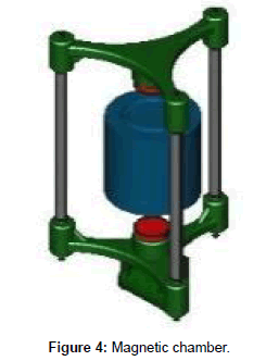
The Magnetic Chamber uses the magnetic force from an Electromagnet and Permanent Magnet repelling and attracting to each other to turn a crankshaft. The linear motion of the Magnetic Chamber is converted into circular force and torque. The Magnetic Chamber is composed of one Opposite Pole Electromagnet, two Permanent Magnets, three Magnetic Frame Rails, and two Frame Plates (Figure 4).
The Opposite Pole Electromagnet and the Permanent Magnets produce magnetic forces. These forces will repel or attract each other. The Opposite Pole Electromagnet has one pole at either end of the electromagnet. The pole can be either North Pole or South Pole and can be reversed by changing the polarity.
The Opposite Pole Electromagnet is suspended in the middle of the Frame with a Permanent Magnet at either end. The Opposite Pole Electromagnet is powered by electricity. The magnetic force from the Electromagnet and the Permanent Magnet repelling and attracting will move the Frame which is connected to the Connecting Rod.
The Frame and Passive Magnetic Linear Bearings are combined into one. A full stroke will be achieved through the Frame moving in a linear motion that travels the full length of the Magnetic Chamber in both directions. The distance that it travels will be pushed and/or pulled by the magnetic forces from the magnets. The Passive Magnetic Linear Bearings is connected to the engine block. The bars have a Permanent Magnet mounted on them. The bottom bar is connected to the Magnetic Connecting Rod.
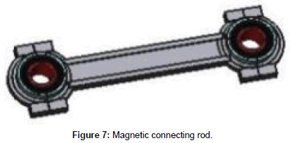
The Magnetic Connecting Rod is composed of two Electrodynamic Bearings, one at each end of the rod. The Magnetic Connecting Rod is connected to the crankshaft. The crankshaft is mounted to the engine block by the Active Magnetic Bearings. The crankshaft is connected to a flywheel and alternator or a transmission.
The movement of the Frame is called a stroke. A stroke is when the Frame moves down and up. Every movement of the Frame creates power for the engine. The strokes are divided into two parts, the Down Stroke and Up Stroke which are half of a stroke.
Down Stroke: The Bottom Permanent Magnet is close to the Opposite Pole Electromagnet Bottom Pole. The power is turned ON at the top of the stroke; the Opposite Pole Electromagnet Bottom Pole polarity is set to North Pole repelling the Bottom Permanent Magnet and then turned OFF. The Frame moves down, when the Frame is 2/3 down the power is turned ON with the polarity and the Opposite Pole Electromagnet Top Pole is set to the South Pole, attracting the Top Permanent Magnet then power is turned OFF at the bottom of the stroke.
Up Stroke: The Top Permanent Magnet is close to the Opposite Pole Electromagnet Top Pole. The power is turned ON at the bottom of the stroke; the Opposite Pole Electromagnet Top Pole polarity is set to North Pole repelling the Top Permanent Magnet and then turned OFF. The Frame moves up, when the Frame is 2/3 down the power is turned ON with the polarity and the Opposite Pole Electromagnet Bottom Pole is set to the South Pole, attracting the Bottom Permanent Magnet and then power is turned OFF at the bottom of the stroke.
Chamber material: The Magnetic Chamber will be composed of two different types of material, nonmagnetic and magnetic shielding. The nonmagnetic material is used to prevent any magnetic attraction between materials. The Chamber, Frame, Frame Rail, Connecting Rod and the Electromagnetic mount will be composed of the same material.
The Magnetic Shielding material will be used to prevent any magnetic interference from the Electromagnets and Permanent Magnets. The material will encircle the chamber to redirect any electromagnetic waves.
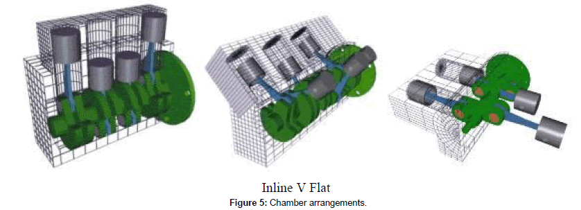
Chamber arrangements: The engine configuration will vary depending on the need of the engine and the horsepower required. The number of Magnetic Chambers can be increase to increase the horsepower (Figure 5).
Temperature control system
The Temperature Control System is designed to keep the electromagnets at operational temperature (14° F to 104° F). The electromagnets produce heat during operation. During cold temperature more heat may be required; the system will have an Electric Heating Coil to increase the temperature to the operational range. The system will be controlled by the Engine Management Unit (EMU).
The Temperature Control System operates with four objectives:
1. Temperature within operational range – The Hot Electric Valve is closed, sending coolant to the Radiator Bypass. The Radiator Bypass will send the coolant through the Electric Heating Coil, which is off, then to the Cool Electric Valve. The Cool Electric Valve is closed, sending coolant to the Electric Coolant Pump. The Electric Coolant Pump will send coolant to the electromagnets.
2. Temperature below operational range – The Hot Electric Valve is closed, sending coolant to the Radiator Bypass. The Radiator Bypass will send the coolant through the Electric Heating Coil, which is off, then to the Cool Electric Valve. The Cool Electric Valve is closed, sending coolant to the Electric Coolant Pump. The Electric Coolant Pump will send coolant to the electromagnets.
3. Temperature above operational range – The Hot Electric Valve is open, sending coolant to the Radiator. The Radiator will send the coolant to the Cool Electric Valve, which is open. The Cool Electric Valve will send the coolant to the Electric Coolant Pump. The Electric Coolant Pump will send coolant to the electromagnets.
4. Temperature above electromagnet safety range – The Engine Management Unit will shut down the engine. The Hot Electric Valve is open, sending coolant to the Radiator. The Radiator will send the coolant to the Cool Electric Valve, which is open. The Cool Electric Valve will send the coolant to the Electric Coolant Pump. The Electric Coolant Pump will send coolant to the electromagnets.
Crankshaft system
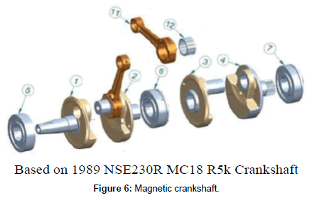
The crankshaft will be designed to operate at a half stroke, receiving power every half a revolution.
Magnetic crankshaft: The crankshaft will be supported by Active Magnetic Bearings and uses Electrodynamic Bearings on the Magnetic Connecting Rods (Figure 6).
Magnetic connecting rod: The Electrodynamic Bearings are used at both ends of the Connecting Rod. The Connecting Rod connects the crankshaft to the Magnetic Chamber. The Electrodynamic Bearings are Magnetic Bearings that uses permanent magnets (Figure 7).
Magnetic bearings system
The Electromagnetic Reciprocating Engine is designed to use magnetic levitation on all moving parts. The engine will use NO Oil for lubrication. The engine will use Magnetic Bearings. Magnetic Bearings support the highest speeds. The lubrication system is composed of the Active Magnetic Bearings, Electrodynamic Bearings, and Passive Magnetic Linear Bearings.
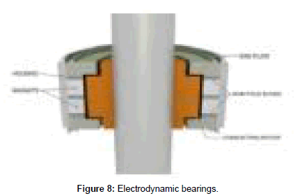
Electrodynamic bearings: “The bearing solution is working with currents induced by the rotating of a shaft in a permanent magnetic field.When the shaft is in its center position there are no induced currents present.When applying a force to the shaft the shaft is offcentered. Once off centered – currents start to flow in the construction (Figure 8).
On one side this will result in a pushing force (small black arrow where the air gap is smaller). On the other side – where the air gap is larger – a pulling force (small black arrow pulling the bearing towards its center position) will help reposition the shaft.”
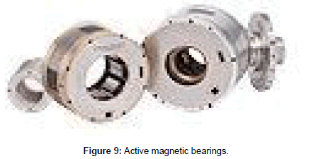
Active magnetic bearings: The Active Magnetic Bearings are designed to support the crankshaft. The Active Magnetic Bearings is the principle which is actually used most often among the magnetic suspensions. The figure explains the components and the function of a simple bearing. A sensor measures the displacement of the rotor from its reference position, a microprocessor as a controller derives a control signal from the measurement, a power amplifier transforms this control signal into a control current, and the control current generates the magnetic forces within the actuating magnet in such a way that the rotor remains in its hovering position. The control law is responsible for the stability of the hovering state as well as the stiffness and the damping of such a suspension (Figure 9).
Passive magnetic linear bearings: The Passive Magnetic Linear Bearings is the magnetic guide rail for the Magnetic Chamber. It guides the Magnetic Chamber through the engine block and it connects the top and bottom magnet plates.
Proprietary Information
Electrical system: The Electrical System is designed to manage the electricity and manage the engine. There are different voltages depending on the engine requirements. One volt is based on the requirement of the electromagnets. The second volt is a 12VDC system for the engine control systems.
Engine management unit: The Engine Management Unit (EMU) monitors and controls the engine.
Monitors and Controls:
• Timing in the Magnetic Chamber
• Temperature of the electromagnets
• Active Magnetic Bearings
• Electricity input (set idle)
• Battery Charging System
• Starting System
Engine timing: The engine timing is designed to control the timing and the amount of electricity sent to the electromagnets in the Magnetic Chamber. Because the Magnetic Chamber is connected to the crankshaft, the position sensor is mounted to the crankshaft. This allows one sensor to control multiple Magnetic Chambers.
The Timing system will be controlled by the EMU. The crankshaft sensor will track the position of the Magnetic Chamber. That information is used to turn the electromagnets ON / OFF and the amount of magnetic force from the electromagnets.
Engine operations
The Electromagnetic Reciprocating Engine will operate in a simple manner. To start the engine, insert the key, and all of the Electrical Systems will come online, powered by the 12V battery. The EMU will retrieve information from the sensors and power the starter to move the Magnetic Chambers into the start position. Press the start button once, the EMU will send electricity from the battery to the Magnetic Chambers in a timing order. The starter will start spinning the crankshaft. The crankshaft is connected to the alternator. Once the alternator is turned to the correct RPMs, the electricity will be sent to the Magnetic Chambers and the Electrical System. The electricity from the batteries will disconnect and the batteries will be charged from the alternator. The engine is running on idle.
Engine material
Aluminum alloys: Aluminum alloys is most of the parts in the engine. Aluminum is a non-ferrous metal, nonmagnetic. All parts will be anodized depending of the location of the part.
Aluminum Hard Coat Anodizing MIL-A-8625 Type III Class 1 (Non-Dyed) and Class 2 (Dyed)
Benefits of Hard Coat Anodized Aluminum
• Corrosion resistance
• Non-conductive
• Increased wear resistance
• Increased abrasion resistance
• Light weight properties
Titanium round rod: The Titanium Round Rod is lightweight & strong to support the magnetic shaft.
Braided electrical wire: The braided electrical wire will protect the wire from electromagnetic interference.
Braided hoses: The braided hose will be used in the Temperature Control System.
Magnetic Pulse Engine
The Magnetic Pulse Engine is the version of the Electromagnetic Reciprocating Engine is designed for vehicles. This version is connected to an alternator for electricity and transmission to move the vehicle.
The Electromagnetic Reciprocating Engine can be placed in any vehicle from a car to Semi Trucks (Class 4 – 8). The following engine sizes are divided into two types, Mag and Mag Power. The difference is the torque from the strokes of the crankshaft. The Mag is based on the Gasoline Engine. The Mag Power is based on the Diesel Engine.
The Magnetic Pulse Engine is designed:
• Unlimited Range
• Low Maintenance Cost (110,000 h) (Table 6).
| Name | Renew | Max | IC | Chamber |
|---|---|---|---|---|
| HP | HP | |||
| Mag V82 | 82 | 117 | 35 | 2 |
| Mag V176 | 176 | 252 | 100 | 4 |
| Mag Power V1153 | 1153 | 1647 | 300 | 6 |
| Mag Power V2830 | 2830 | 4042 | 600 | 6 |
Table 6: Magnetic Pulse Engine.
Magnetic pulse generator
The Magnetic Pulse Generator is the version of the Electromagnetic Reciprocating Engine designed to produce clean renewable electricity. This version is connected to a generator.
Generation Usages:
• Electrical Grids
• Electrical Microgrids
• Home and Buildings electricity
• Portable generator
• Power for water purification systems
The Magnetic Pulse Generator can produce various amounts of electricity depending on the size of the Electromagnetic Reciprocating Engine and the size of the generator. The electricity requirements of the generator will dictate the size of the engine.
The Magnetic Pulse Generators are placed anywhere, on buildings; replace substations in a city, in small villages, and on Islands in the middle of the oceans.
The Magnetic Pulse Generator is:
• Low Maintenance Cost (110,000 h)
• Placed anywhere
• Replace Electricity Substations
• Replace large power plants (Table 7).
| Magnetic Pulse Generator | ||||
|---|---|---|---|---|
| Name | Renewable | Chamber | RPM | |
| HP | kW | |||
| Mag V176 | 176 | 129 | 4 | 7000 |
| Mag V355 | 355 | 261 | 6 | 7000 |
| Mag Power V1,153 | 1153 | 847 | 6 | 7000 |
| Mag Power V5700 | 5699 | 4189 | 8 | 7000 |
Table 7: This is an example of engines that can be sized at needed.
Smart Microgrid: The Magnetic Pulse Generator Smart Microgrid is a Microgrid that has electrical generators spread throughout the grid. Microgrids are basically self-contained electrical ecosystems. Electricity is produced, transmitted, consumed, monitored, and managed all on a local scale. In many cases, they can be integrated into larger, central grids, but their defining characteristics are that they can operate independently if disconnected from the whole.
The Magnetic Pulse Generator Smart Microgrid does not depend on large power plants and high voltage power lines. Each generator can produce 5+ MW of renewable electricity. The generators are combined to produce the required electricity. The generators are controlled by a Management Center.
Benefit:
• Clean renewable electricity
• Be placed anywhere
• Resistant to weather
• Robust, redundant grid design
• Does not require large power plants
Water purification: The Magnetic Pulse Generator will be used with water cleaning systems that can clean any kind of water. The Magnetic Pulse Generator will provide electricity for the following:
• Water Pumps
• Pre Water Filter
• Electronic Water Purification (remove Minerals)
• Reverse Osmosis Systems (Cleans Water)
• Ultraviolet Light (Disinfects Water)
Magnetic pulse motor
The Magnetic Pulse Motor is the version of the Electromagnetic Reciprocating Engine designed to move trains and ships. This version is composed of the Magnetic Pulse Generator to produce electricity and a standard electric motor.
The Magnetic Pulse Motor can increase the horsepower by increasing the number of Magnetic Pulse Generators. This increase in electricity will increase the horsepower and torque of the electric motor.
The Magnetic Pulse Motor is designed:
• Low Maintenance Cost (110,000 h or 12 years)
• Produces large amount of horsepower & torque (Table 8).
| Magnetic Pulse Motor | ||||
|---|---|---|---|---|
| Name | Renewable | Chamber | RPM | |
| HP | kW | |||
| Mag Power V600 | 601 | 441 | 6 | 7000 |
| Mag Power V1,574 | 1574 | 1157 | 6 | 7000 |
| Mag Power V2,830 | 2830 | 2080 | 6 | 7000 |
| Mag Power V5,700 | 5699 | 4189 | 8 | 7000 |
Table 8: This is an example of engines that can be sized as needed.
Magnetic pulse aircraft engines
The Magnetic Pulse Aircraft Engines is the version of the Electromagnetic Reciprocating Engine designed for aircraft. This version is connected to an alternator for power and a propeller.
The Magnetic Pulse Aircraft Engine is designed:
• Low Maintenance Cost (110,000 h or 12 years)
• Unlimited Range (Table 9).
| Magnetic Pulse Aircraft Engine | ||||
|---|---|---|---|---|
| Name | Renew | Max | IC | Chamber |
| HP | HP | |||
| Mag V82 | 82 | 117 | 35 | 2 |
| Mag V176 | 176 | 252 | 100 | 4 |
| Mag Power V1153 | 1153 | 1647 | 300 | 6 |
Table 9: This is an example of engines that can be sized as needed.
Conclusion
The Electromagnetic Reciprocating Engine will end businesses dependence on Oil, reducing their operating cost. The Electromagnetic Reciprocating Engine will replace the Combustion Engine in electricity production and transportation.
The Electromagnetic Reciprocating Engine will reduce the effects of Climate Change. The engine will end over 60% of greenhouse gases which will affect the climate of the World. The engine will end over 75% of the Worlds dependency on Oil.
The Electromagnetic Reciprocating Engine:
• NO Fossil Fuels
• Produces NO CO2 – environmentally clean
• Produces more HP then the Combustion Engine
• Placed in any vehicle
• Renewable Electricity 2 kW – 9 MW per engine
The Electromagnetic Reciprocating Engine is a Mechanical Renewable Energy System and the World’s First Truly Green Engine.
References
Citation: Butler K (2015) Electromagnetic Reciprocating Engine White Paper. Innov Energ Res 4: 118. DOI: 10.4172/2090-5009.1000118
Copyright: ©2015 Butler K. This is an open-access article distributed under the terms of the Creative Commons Attribution License, which permits unrestricted use, distribution, and reproduction in any medium, provided the original author and source are credited.
