Electric Speed Governor for 1kw Microhydro Generator
Received: 11-Oct-2017 / Accepted Date: 13-Oct-2017 / Published Date: 20-Oct-2017 DOI: 10.4172/2576-1463.1000174
Abstract
Electricity performance is characterized by the stability of voltage and frequency of the generator. To maintain the electricity performance, the generator speed is held stable at its nominal speed using a governor system. Electric governor system commonly used on hydro power plant. However in this study the electric governor system was developed for microhydro power plant. The Electric governor system was developed using NI myRIO® 1900 microcontroller device to accelerate the response due to load variations, and can be functioned as monitoring equipment.. The microcontroller device obtained input signal from generator speed sensor, voltage and ampere meter, and the position of the wicket gate. Afterwards, the microcontroller regulate the required wicket gate opening and the generator speed can be held stable. The governor system developed for 3000 rpm, 220 V, and 1 kW generator. The data obtained from this study shown that the developed electrical governor system has a 20-second response time to return the generator's speed to its nominal speed with load variations given to the generator is every 20% (200W). Operational shutdown system by the governor system due to the instability of the generator speed takes 24 s.
Keywords: Electric governor; NI myRIO®; Microhydro power
23199Introduction
Generally, performance of electricity production in microhydro/picohydro is one of problematic issue due to poor load control system. Load controls on microhydro systems generally use Electronic Load Control (ELC), whereas unloaded power production is shifted to ballast load. While, picohydro system is not using the load control system. This results in poor performance of electricity production.
To produce good performance of electricity production, the generator speed must be held stable at its nominal speed. A device used to maintain the stability of the turbine/generator speed is the governor system. The governor system commonly used for power generation is a mechanical governor system that requires many supporting components and has a low system response.
The recent development of microcontroller technology enable the convertion of mechanical governor system to electrical governor system [1-3]. Microcontroller equipment used in this research is NI myRIO® 1900 from National Instrument. The NI myRIO® 1900 device can be used for control, data recording, or data communication device. LABVIEW software is used for programming the microcontroller.
Methodology
The research approach in developing electric governor system begins with information about the limitations of load control system for microhydro. To overcome good performance of electricity production, it is necessary for the control system to maintain the generator speed at its nominal speed by adjusting the flow rate of water to turbine. The signal input of the electrical governor system obtain from the generator speed, generator voltage, generator current, valve opening position and load breaker system position. The signals processed by the microcontroller to regulate the flow rate of water that enters the turbine by controlling the valve opening, as well as maintaining the generator turbine system working in the design range limit. In this research, a microcontroller NI myRIO® 1900 (National Instrument product) is used.
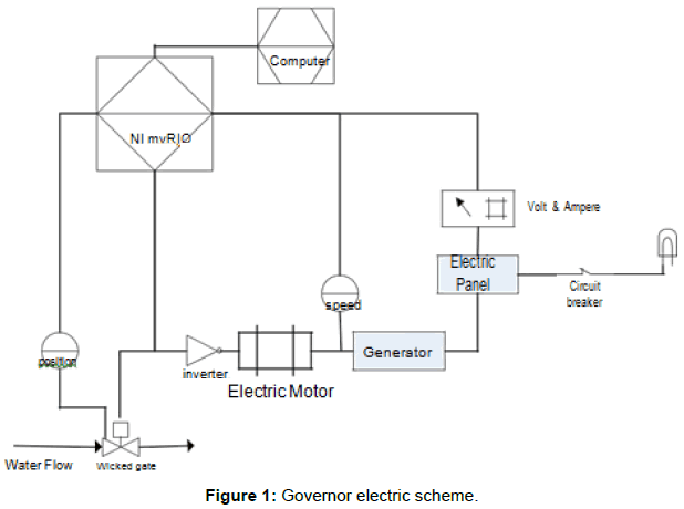
The research is focused on the development of electrical governor system, while the protection system for the vibration and temperature of the generator bearings will be developed later on next research. The working principle of electrically developed governor is tested with an electric motor equipped with inverter to replace the function of the turbine as shown in Figure 1.
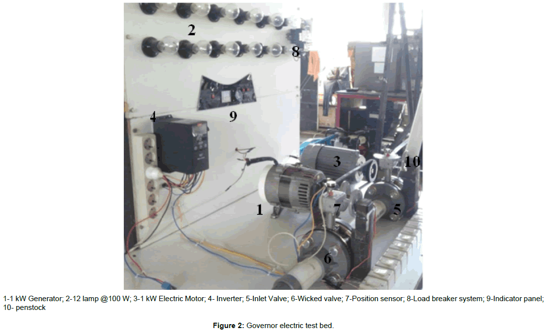
The test bed of an electric governor system is shown in Figure 2. The equipment used for electrical governor system testing is based on 1 kW, 3000 rpm, 220 V, 50 Hz generators. The turbine function is replaced by an electric motor equiped with inverter. The water flow on the penstock passes the inlet valve and the wicket gate. Twelve incandescent lamps (100W each) is used as generator load.
Rotational speed of generator is measured by photointerupter, while potentiometer is used for sensing the position of the inlet valve and wicket gate. Volt meter and ampere meter are used for measuring generator load. The data are then processed on the microcontroller NI myRIO® 1900 and the output is to command wicket gate to actuate and electric motor inverter to operate.
The test is done by increasing the generator load with a 20% increase in each step. Meanwhile, to test the generator overload speed, the load is given 110% of the generator nominal load.
Result And Discussion
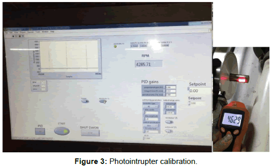
The rotational speed measurement by the photointerupter is displayed on the computer using LABVIEW software. The photointerupter measurement is calibrated using tachometer to obtain deviation in the measurement. The calibration of the rotational speed sensor (photointrupter) is shown in Figure 3 and the result of comparison between the photointrupter sensor with the tachometer shown in Table 1.
| NO | Tachometer | Photointruptor |
|---|---|---|
| 1 | 4629 | 4285 |
| 2 | 4513 | 4315 |
| 3 | 4229 | 4198 |
| 4 | 4391 | 4539 |
| 5 | 4329 | 4245 |
Table 1: Photointrupter testing.
The measurement of rotational speed repeated in 5 times with the generator condition without load. The average value of tachometer measurement is 4418.2 rpm and the photointerupter reading is 4316.4 rpm. The deviation of the measurement is calculated by:

= 2.4%
The setting point of the generator rotational speed is ± 5% of the nominal speed (3000 rpm).. If within a time range of 20 s the generator speed under 2850 rpm or over 3150 rpm, the control system will shutdown the generator operation.
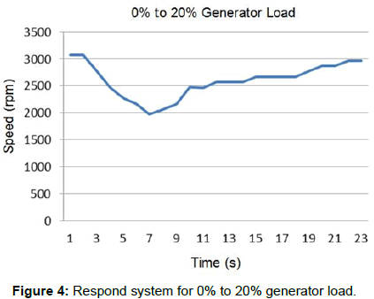
Figure 4 shows the generator response on a 20% load increase (200W) causes a decline in generator rotational speed of 1968 rpm in 7 s, while the response of the electric governor system to return the generator rotational speed to its limit (2850 rpm) takes 20 s and reaches its nominal speed at 23 s. The speed of generator down to 34% of the nominal speed is due to the high load increase in the instantaneous time. After reaching the nominal speed the generator load is increased by 20% so that the generator load reaches 400W. The graph of the electrical governor system's response for 40% (400W) load is shown in Figure 5.
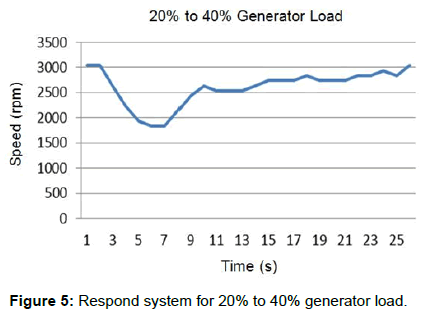
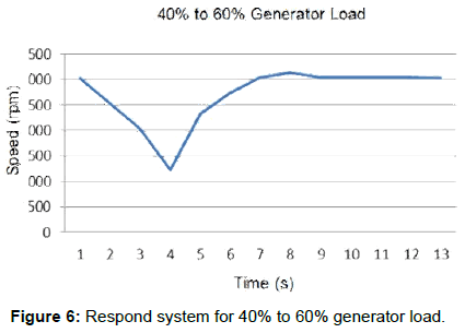
The Figure 5 shown that the generator rotational speed drop to 1838 rpm. The governor system can return the generator's rotational speed to its minimum threshold (2850 rpm) within 17 s and return to its nominal speed with a time of 23 s. After the generator speed is stable at its nominal speed with a load of 400 W (40%), then the generator load is increased by 20% or the generator load becomes 600W (60%). The governor's system response for that condition is shown in Figure 6.
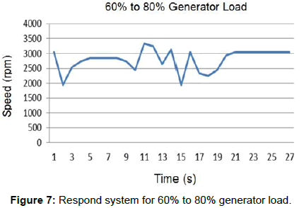
For 60% load as shown in Figure 6, the governor system is fairly well to return the generator speed to its nominal speed by 8 s. This result from the fast response of the wicket gate servo motor to open, so that the required water flow rate can be achieved rapidly. At the 80% generator loading step there is a vibration on the generator shaft causing an unstable generator rotational speed measurement. The graph of electric governor's response to 80% loading is shown in Figure 7.
The experiment on 80% load shown the microcontroller respond time is 20 s to return the generator rotational speed to its nominal speed. At the time range between 9 to 19 s, fluctuation of rotational speed measurement on the photointerupter occurs caused by the vibration of the generator axle. The fluctuation of the measurement impacted to instability of the wicket gate opening.
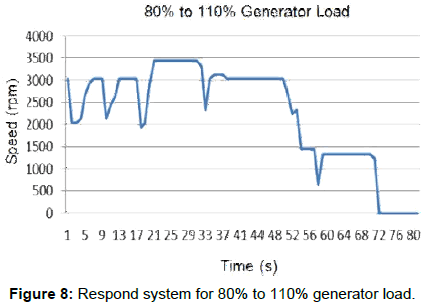
In the final step, generator is given a load increase by 30% (300W), so at this step the generator is loaded 110% of its nominal capacity. With the excess load in the generator is expected to know the response from the governor system. The graph of the governor's response at this stage is shown in Figure 8.
At the loading of 110% of the vibrations that occur on the generator is excessive causing hunting on generator speed and valve opening. With the system hunting of more than 20 s, the governor command for the termination of system operation that occurred at 48 s.
Conclusion
As a result of electric governor testing, it can be concluded as follows:
1. Electrical governor systems using NI-MyRio devices can be applied to replace mechanical governor systems and monitoring devices for microhydro or picohydro systems.
2. The use of photointruptor sensors in this study as rotational speed sensor has a reading error of 2.4%
3. The governor's system response can return the generator's speed at its nominal speed less than 20 s.
4. Operation termination system that is done by system governor because of instability of generator rotation takes 24 s.
Acknowledgement
The Authors wish to thanks the Riset dan Teknologi Pendidikan Tinggi (RISTEK-DIKTI) for their tremendous support. The authors would also thank the Mechanical Engineering Departement, Industrial Technology Faculty, Institut Teknologi Nasional Bandung.
References
- Marius AM, Daniela V, Nicolae V, Radu P, Constantin C? LINOIU, 2013. A new generation of speed governors for kaplan turbines. U.P.B Sci Bull 75: 140-150.
- Nagizadeh RA, Jazebi S, Vahidi B (2012) Modeling hydro power plant and tuning hydro governor as an educational guideline. International review on modeling on simulation (I.RE.MO.S.) 5: 1780-1790.
Citation: Sirodz MPN, Purwanto TS, Hermanto A, Barata IAN, Taufiqullah (2017) Electric Speed Governor for 1kw Microhydro Generator. Innov Ener Res 6: 174. DOI: 10.4172/2576-1463.1000174
Copyright: ©2017 Sirodz MPN, et al. This is an open-access article distributed under the terms of the Creative Commons Attribution License, which permits unrestricted use, distribution, and reproduction in any medium, provided the original author and source are credited.
Share This Article
Recommended Journals
Open Access Journals
Article Tools
Article Usage
- Total views: 7498
- [From(publication date): 0-2017 - Dec 18, 2024]
- Breakdown by view type
- HTML page views: 6723
- PDF downloads: 775

