Research Article Open Access
Discontinuity Attributes, their Visualization and Seismic Interpretation: Case Studies from Indus Basin, Pakistan
Asif AA*, Rehman EA, Shoaib K, Anjum AG and Mustafa RK
Kuwait Foreign Petroleum Exploration Company (KUFPEC), 3rd floor, Ufone Tower, 55-C, Jinnah Avenue, Islamabad, Pakistan
- *Corresponding Author:
- Asif AA
Kuwait Foreign Petroleum Exploration Company (KUFPEC)
3rd floor, Ufone Tower, 55-C, Jinnah Avenue
Islamabad, Pakistan
Tel: 0923345438773
E-mail: aasif@kufpec.com
Received date: November 26, 2015; Accepted date: December 18, 2015; Published date: December 23, 2015
Citation: Asif AA, Rehman EA, Shoaib K, Anjum AG, Mustafa RK (2015) Discontinuity Attributes, their Visualization and Seismic Interpretation: Case Studies from Indus Basin, Pakistan. Oil Gas Res 2:107. doi: 10.4172/2472-0518.1000107
Copyright: © 2015 Asif AA, et al. This is an open-access article distributed under the terms of the Creative Commons Attribution License, which permits unrestricted use, distribution, and reproduction in any medium, provided the original author and source are credited.
Visit for more related articles at Oil & Gas Research
Abstract
There are a number of discontinuity attributes that are considered useful for identifying faults and small fractures that can’t be fully delineated using seismic amplitude data. Out of the many available discontinuity attributes, curvature and coherence have been selected because of their proven abilities to delineate faults/fractures effectively and also their suitability to the subsurface structures present in case of volumes used. This paper highlights the practical importance of curvature and coherence attributes applied on two seismic data sets (3D volumes) from Indus basin, Pakistan, both exhibiting extensional tectonics. Curvature attributes can be measured in different directions but mostpositive and most-negative curvature are found to be of best use in highlighting extensional regime’s geometry very effectively. Apart from highlighting faults across a 3D cube, curvature attributes also give useful information about the highs and lows present in the data set that can be well correlated with the subsurface geology. Coherence checks for similarity between adjacent seismic traces and can be calculated using different techniques like crosscorrelation, semblance and eigen structure measures after analyzing dips and azimuths. Coherence and curvature (most negative and most positive) cubes have been extracted using conventional Pre-stack seismic volumes after a careful selection of parameters. Different examples have been included, compared and explained with reference to coherence and curvature results. The use of mentioned attributes effectively demarcated faults’ orientations and their lateral and vertical extents. Many of the small faults that were not clearly visible on conventional seismic data were well highlighted using attributes’ results viewed and analyzed along time-slices as well as horizon slices.
Keywords
Discontinuity attributes; Seismic data; Seismic interpretation; Seismic attributes
Introduction
Lower and Middle Indus basins of Pakistan fall in extensional to trans-tensional tectonic regime and hence are characterized by horstgraben features, tilted fault blocks and strike-slip zones with associated negative flower patterns. Horst blocks, tilted fault blocks and gentle roll-overs form the main hydrocarbon traps.
3D Seismic attributes can be of great help in delineating subsurface fault networks, their orientations and their lateral and vertical extents. Accurate or a reliable fault/fracture extraction method surely affects the reserve estimations and hence it’s of great importance. Faults and fractures have an important role in understanding fluid flow and hydrocarbon entrapment [1]. Correct marking of faults on time and depth seismic sections or volumes aid in enhanced fault seal analysis and hence it can help a company in making its future decisions about drilling wells at optimum locations. Seismic attributes for faults/ fractures detections are called discontinuity attributes which include Coherence and Curvature attributes apart from a number of available seismic attributes like dip azimuth, dip variance, dip of maximum similarity, edge- detection etc. Their names vary to a great deal as far as different seismic interpretation software packages are concerned.
Need for using seismic attributes
It is really important to examine a 3D seismic volume before starting interpretation on it. 3D visualization techniques offered by different software packages is of great use and one should take maximum benefit from it. A 3D processed volume (amplitude data) should be analyzed thoroughly in all directions i.e. Time-slice, inline and crossline directions. Chair displays combined with different options of oblique-cut views in a 3D window are greatly facilitating seismic interpreters these days.
In case of a properly designed, acquired and processed seismic volume, 3D visualization itself provides useful information about target horizons’ dips, amplitude anomalies, hints of faults’ presence, presence of alien bodies like salt diapers or igneous intrusions and amplitude anomalies. It indeed requires the interpreter’s grip over geology of the area apart from his/her abilities to pick the things quickly and differentiate between subtle variations. However, it is not always easier to achieve the desired goals just from 3D visualization of a traditional seismic data because of presence of different types of noises, inadequate processing steps and geological complexities of the subsurface. Moreover, small faults and fractures are often beyond seismic resolution. This is the point where a seismic interpreter feels the need of using some additional tools called seismic attributes. A seismic attribute is a quantity that is derived or extracted from available seismic data which further highlights the features of interest and aids in a reliable seismic interpretation of the area. Broadly speaking seismic attributes are of two types; Pre-stack and Post-Stack [2]. In this paper we will be discussing the application of volumetric Post-Stack attributes related to faults’ detection. These post-stack attributes, if applied with prudence can highlight the features that are not fully detectable on conventional amplitude seismic data.
Modern day seismic interpretation software packages offer a number of post stack seismic attributes and filters that can be applied easily with a little or even without any prior knowledge or expertise. However, one should be careful in selecting and using different attributes as they can result in rendering a false picture of subsurface. Another confusing thing for the newbies or even mid-career professionals is the selection of proper and useful attributes that enhance the seismic interpretation in real sense. It should be clear to a seismic interpreter that what type of features (structural or stratigraphic or both) he/she is looking for and what are the seismic attributes that will be most suitable. Apart from having some basic knowledge before using a particular attribute it should also be taken in to consideration that using different attributes in isolation is not recommended. An anomaly observed using a single seismic attribute should always be re-checked using one or more other attributes. For example, fault patterns identified using one of the available discontinuity attributes can be rechecked using an instantaneous frequency attribute. Frequency attribute can be a good indicator of fracture zones as fractures normally appear as lower frequency zones.
Data set description
Alpha 3D survey has an area of about 100 sq.km (subsurface coverage) with a bin spacing of 25 m 25 m. It lies in Southern Indus Basin and hence features typical extensional belt’s geometry. Subsurface geology is complex because of presence of an igneous intrusion in form of a saucer shaped sill that cuts through shallower and deeper horizons making seismic interpretation a challenging job. As this sill is a post faulting event, it is cutting across nearly all the faults but following the general trend of highs and lows in the area. This sill is masking the fault continuity and even the much bigger throws (>200 ms) across some faults. This area is yet to be explored fully for hydrocarbon potential [3]. Using discontinuity attributes has greatly helped in interpreting the data set.
Beta 3D survey has an area of about 300 sq.km (subsurface coverage) with the same bin spacing of 25 m × 25 m. It is one of the largest gas fields of Pakistan which lies in middle Indus Basin. The subsurface is extensively faulted with presence of shear zones (strike-slip faulting) on amplitude data (default 3D volume). Application of discontinuity attributes did a very good job in understanding the fracture patterns in detail here.
Both 3D data sets are Pre-Stack time migration volumes. They are checked for any seismic processing artefacts and noise levels before application of discussed seismic attributes. Signal to noise ratio in Beta 3D is a little better than Alpha 3D.
Discontinuity attributes
Discontinuity attributes are considered very good tools for identifying discontinuities or faults and even smaller fractures present in the seismic data which can’t be fully delineated just on the basis of conventional amplitude data. Discontinuity attributes normally include Dip Magnitude, Dip Azimuth, Dip Variance, Curvature (Minimum, Maximum, Gaussian, Mean, Most-positive, Most- negative etc.,) and Similarity or Coherence [4]. In this paper the main emphasis is given to volumetric attributes with some attributes extracted along horizons for comparison.
Curvature
Curvature of a surface is the measure of its deviation from being flat. In geological sense, curvature is a measure of curvedness analyzed and calculated in different directions along a bedding plane or a marked reflector in case of seismic [5]. Extraction or calculation of curvature from a seismic volume or along a correctly marked seismic horizon gives a very nice idea of faults’ presence and their extents. Small fractures’ networks delineated on volumetric curvature attributes can be very helpful in placing horizontal wells and future development wells in already producing fields [6].
Curvature estimation or volumetric curvature estimation is done by software suits after analyzing the reflectors’ dips and azimuths in a 3D cube. Curvature attributes can be measured in different directions but most positive curvature and most negative curvature are found to be of best use especially in regimes exhibiting extensional tectonics. Apart from highlighting faults across a 3D cube, curvature attributes also give useful information about the highs and lows present in the data set that can be well correlated with the subsurface geology.
Most positive and most negative curvature attributes produce edge-type display showing faults and lineaments with a polygonal appearance.
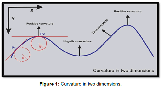
Concept of curvature can be explained with respect to Figure 1.
The curvature at any given point (P1, P2 or any other point) on the blue curve is the reciprocal of the radius of the particular arc at that point. It is natural to define the curvature of a straight line to be identically zero. The curvature of a circle of radius R should be large if R is small and small if R is large [7]. Thus the curvature of a circle is defined to be the reciprocal of the radius:
k = 1/R
In Cartesian coordinates X-Y, curvature (k) can simply be defined as a second derivative,
k = d2Y/dX2
Curvature is a second derivative based method and consequently sensitive to presence of noise in input seismic volume. However as noise levels in a seismic volume vary between different intervals, curvature results viewed along different time slices are likely to be different. Sometimes a clear lineament observed on a curvature volume for example at 1000 ms will not appear on intermediate time levels for example (1100 ms to 1400 ms) because of chaotic reflection patterns present in input seismic volume between mentioned time interval. Because of noise present in the seismic data, resulting curvature will also generate noise making the observed feature unidentifiable. That observed lineament or fault can appear again (if it really exists) on deeper time slices where seismic data from which curvature values have been extracted has fair to good signal to noise ratio.
Using curvature attribute or extracting it from default amplitude seismic volume there are certain parameters to be taken care of. Different seismic interpretation software suits will require more or less similar parameters for calculation. There are inputs required from interpreters regarding max dip expected in the seismic volume and dip scan increment. There is also a bandpass filter which allows one to limit the undesired low and high frequencies. Obviously one can provide these values after analyzing the frequency spectrum of input data. Time/depth search window for comparing adjacent seismic traces should always be appropriate to delineate the subtle features. Too short or two wide windows are not recommended. Depending on the subsurface structures, fault patterns and throws one can generate different curvature volumes with different time/depth search windows to get the optimum results.
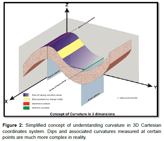
Figure 2 is just a simplified 3D version of Figure 1 further highlighting the concept of curvature.
Visualization and seismic interpretation
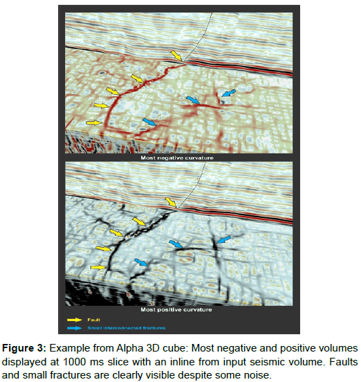
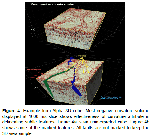
Most positive and most negative curvature attributes extracted from a 3D seismic amplitude data (PSTM) can be best viewed along a time slice (Figure 3) or a horizon slice. On vertical seismic sections or a cube examined vertically, they will show hints of fracture zones and major faults but not enough to draw any meaningful conclusions (Figures 4a and 4b).
Figure 4: Example from Alpha 3D cube: Most negative curvature volume displayed at 1600 ms slice shows effectiveness of curvature attribute in delineating subtle features. Figure 4a is an uninterpreted cube. Figure 4b shows some of the marked features. All faults are not marked to keep the 3D view simple.
In Figure 3, most negative curvature has picked the discontinuities in red (negative values or min curvature) while most positive curvature has picked in black (positive values or max curvature). Fault indicated by yellow arrows is a normal fault with a throw of 40 ms. Selection of colour bar also has also great importance in delineation of features on time slices or horizon slices from which the curvature values have been extracted. In Figure 3 one of the most commonly used colour bars, red-white-black (available in all interpretation software packages with different names) is used. Black here corresponds to peaks in the conventional seismic volume whereas red shows the troughs.
In Figure 4b green and blue faults intersecting to form a lambda geometry are the two major faults in the area. Area between these faults is a big horst block extending further south of Alpha 3D.
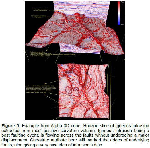
As discussed earlier curvature values can also be extracted along an interpreted horizon. This particularly facilitates to understand the fracture patterns in reservoirs and can be helpful in designing fracking jobs in case of tight reservoirs. However we have extracted curvature values (most positive) along an igneous intrusion to show the effectiveness of this attribute (Figure 5).
Figure 5: Example from Alpha 3D cube: Horizon slice of igneous intrusion extracted from most positive curvature volume. Igneous intrusion being a post faulting event, is flowing across the faults without undergoing a major displacement. Curvature attribute here still marked the edges of underlying faults, also giving a very nice idea of intrusion’s dips.
In case of an ideal flexure or a monocline, curvature attribute will produce a pair of lineaments, one of positive values and one on negative values representing two hinges of the flexure. However geological features are far more complex than deemed. In case of igneous intrusion curvature attribute did produce sets of almost parallel running lineaments (Figures 4 and 5) that were discontinuous at places because of changes in measured curvatures along the igneous intrusion.
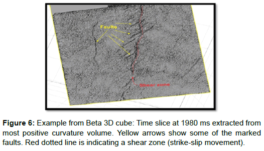
Figure 6 shows a most positive curvature slice taken at 1980 ms from Beta 3D cube (curvature volume). Note that despite a noisy appearance, curvature has successfully delineated faults and a shear zone.
Coherence
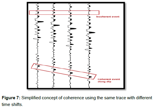
Coherence or similarity compares adjacent seismic waveforms using techniques like cross-correlation, semblance and eigenstructure measures after analyzing dips and azimuths. In simpler words coherence attribute examines or measures degree of similarity between two or more seismic traces. Figure 7 gives a simplified view of this concept.
Coherence estimation or volumetric curvature estimation is done by software suits after analyzing the reflectors’ dips and azimuths in a 3D cube just like in case of curvature calculations. The inputs required by software suites for generating coherence volumes are almost the same as in case of curvature, the difference is only in the mathematical algorithms running in the background. Here, coherence volumes are generated using semblance algorithm [8].
Low similarity represents faults and fractures. There can be certain artifacts generated if dip scanning (done by software) is not adequate. In case of provided data sets these artifacts are not too distracting. Coherence cubes when viewed along time or depth slices can clearly reveal buried deltas, channels, reefs, igneous intrusions and salt diapers apart from effectively highlighting faults and fractures. Coherence calculations normally apply a low pass filter/filters on analyzed and calculated dips to generate a running average estimate. This is an iterative process which is designed to minimize the effect of local anomalies and spikes. Coherence results appear to be smoother and hence less noisy when compared with curvature [8].
Coherence measurements in three dimensions represent the trace to trace similarity and therefore can produce interpretable changes. Similar traces normally have high coherence values and discontinuities show low coherence values. Regions of seismic traces cut by faults for example, result in sharp discontinuities of trace to trace coherence, producing delineation of low coherence values along fault planes.
Visualization and seismic interpretation:
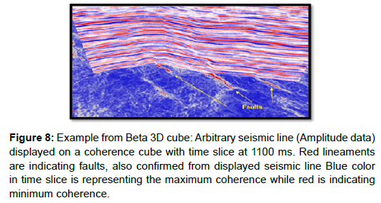
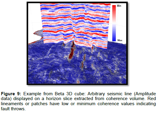
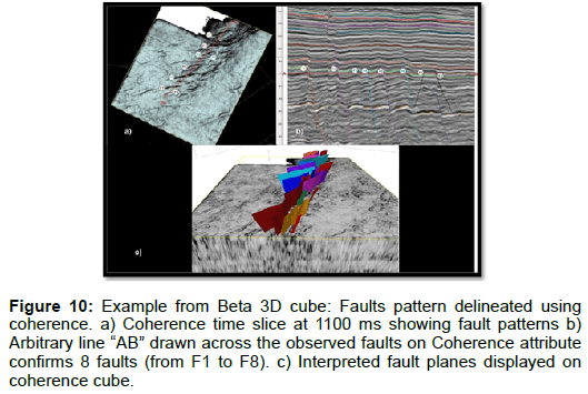
Like Curvature attributes the best way of getting maximum output from coherence volumes is to analyze them in terms of time slices or horizon slices (Figures 8-10). Moreover, the produced results can be better analyzed using appropriate colour bars; use of too many colours can obscure the results by highlighting noise. On a vertical time or depth section extracted from coherence volume the information might not be adequate to draw any meaningful conclusions. In case of 3D data sets with good signal to noise ratio, coherence will indicate presence of shear zones on vertical sections but will not be a good indicator of lateral continuity. On the other hand curvature attribute is a better indicator of lateral continuity (as compared to coherence) but not as good in detecting shear zones as coherence on vertical sections. Figure 8 shows a representative inline from Beta 3D cube:
Figure 8: Example from Beta 3D cube: Arbitrary seismic line (Amplitude data) displayed on a coherence cube with time slice at 1100 ms. Red lineaments are indicating faults, also confirmed from displayed seismic line Blue color in time slice is representing the maximum coherence while red is indicating minimum coherence.
Figure 10: Example from Beta 3D cube: Faults pattern delineated using coherence. a) Coherence time slice at 1100 ms showing fault patterns b) Arbitrary line “AB” drawn across the observed faults on Coherence attribute confirms 8 faults (from F1 to F8). c) Interpreted fault planes displayed on coherence cube.
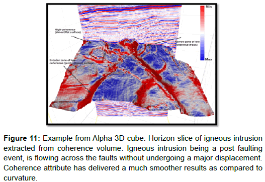
In case of gently dipping strata coherence attribute generates polygonal shaped broader lineaments on time and horizon slices (Figures 10 and 11) unlike curvature attribute which generates sets of parallel running lineaments. The narrower lineaments indicate faults.
Figure 11: Example from Alpha 3D cube: Horizon slice of igneous intrusion extracted from coherence volume. Igneous intrusion being a post faulting event, is flowing across the faults without undergoing a major displacement. Coherence attribute has delivered a much smoother results as compared to curvature.
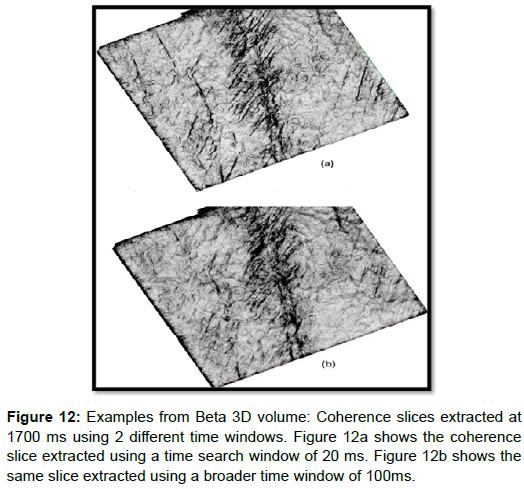
While extracting a Curvature or Coherence volume from a 3D seismic cube, time or depth window for similarity analysis of adjacent traces should be appropriate. It means that it shouldn’t be wide enough to miss the faults with smaller throws nor it should be too narrower as results could be noisier with generation of some pseudo features. Figure 12 explains this statement by comparing two cases; coherence slices are extracted from Beta 3D volume discussed earlier.
Figure 12a looks much more detailed with fault edges sharper and well defined as compared to Figure 12b. The reason for this difference is the inappropriate selection (100 ms) of time window for similarity analysis in second case. Faults with smaller throws (<10 ms) will not be well defined and can also be missed in coherence volumes generated using bigger search windows (80 ms and above in case of Beta 3D volume).
Comparison
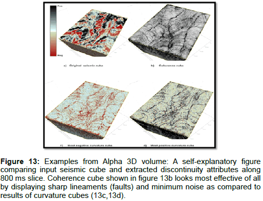
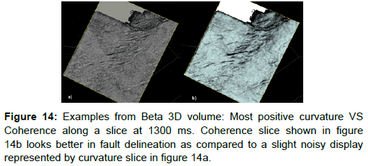
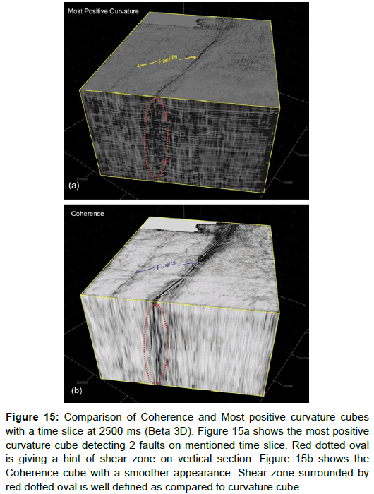
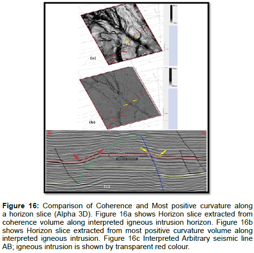
A number of curvature and coherence volumes are generated using different time search windows, viewed and analyzed using different colour bars and compared. Both curvature and coherence effectively delineated faults and fractures, displayed as lineaments. Coherence results in time slices as well as horizon slices are cleaner and detected discontinuities (faults) have sharper edges. Following figures compare the two attributes in detail (Figures 13-16):
Figure 13: Examples from Alpha 3D volume: A self-explanatory figure comparing input seismic cube and extracted discontinuity attributes along 800 ms slice. Coherence cube shown in figure 13b looks most effective of all by displaying sharp lineaments (faults) and minimum noise as compared to results of curvature cubes (13c,13d).
Figure 15: Comparison of Coherence and Most positive curvature cubes with a time slice at 2500 ms (Beta 3D). Figure 15a shows the most positive curvature cube detecting 2 faults on mentioned time slice. Red dotted oval is giving a hint of shear zone on vertical section. Figure 15b shows the Coherence cube with a smoother appearance. Shear zone surrounded by red dotted oval is well defined as compared to curvature cube.
Figure 16: Comparison of Coherence and Most positive curvature along a horizon slice (Alpha 3D). Figure 16a shows Horizon slice extracted from coherence volume along interpreted igneous intrusion horizon. Figure 16b shows Horizon slice extracted from most positive curvature volume along interpreted igneous intrusion. Figure 16c Interpreted Arbitrary seismic line AB; igneous intrusion is shown by transparent red colour.
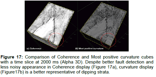
Seismic line “AB” shows portions of gentle dips observed along marked igneous intrusion reflector. Red and yellow arrows have been used here to highlight these portions on seismic as well as on extracted curvature and coherence slices. Figure 16a, the coherence slice display, is a better representation of dipping igneous body by creating darker zones or patches as compared to the sets of parallel or semi-parallel lineaments in curvature slice [9]. By looking at the coherence slice one can easily guess that width of darker zones (low coherence values) is representing the dipping event. Depending on the width of low or minimum coherence values, areal extent of dipping event at a particular place can easily be judged (Figure 17).
Area enclosed by red dotted circle in above figure highlights a major difference between two displays. Like previous comparisons, coherence display is smoother and faults are better defined than curvature but because of extra smoothing coherence is unable to show the hints of dipping strata along mentioned time slice. Coherence compensates well for this observed weakness along horizon slices, even better than most positive or negative curvatures.
Conclusion
Curvature and coherence attributes are powerful tools for enhancing structural interpretation by detecting subtle features that are beyond seismic resolution. They can be best viewed along timeslices and horizon slices. However it is recommended to analyze the input seismic data quality in detail in terms of acquisition and processing before extracting seismic attributes from it. Moreover, a particular data set can be fine-tuned or filtered for getting maximum output from mentioned attributes. These two attributes also work well in highlighting stratigraphic features like buried river deltas, channels, salt domes and reef complexes provided they are applied wisely with apposite selection of parameters discussed earlier in detail. In case of one of the data sets used here, both attributes aided well in understanding geometry, dips and fracture patterns of a large igneous sill. Faults can be studied in detail with information of their lateral and vertical extents provided by curvature and coherence maps. In case of seismic cubes with good signal to noise ratio, these two attributes can effectively differentiate between low and high angle faults and gently or steeply dipping strata. They are also very helpful in a quick seismic interpretation of the area by demarcating major faults’ orientations and associated splays and hence can reduce the time required to map the large seismic data sets. Coherence attribute has proved to be a more appropriate tool to study fault patterns and geometries than curvature because of much smoother displays with minimum noise content. Curvature attribute results look more detailed than coherence but sometimes it can generate enough noise to mask some subtle faults and fractures. It is therefore recommended to apply appropriate noise filters before extracting curvature volume from input data. Blocky sort of noise present in curvature results can be attributed to acquisition foot print noise. Observed discontinuities should be analyzed on both time slices as well as horizon slices using different colour bars to mitigate the chances of likely errors. Based on all the usefulness of discontinuity attributes discussed in this paper, their use along with other seismic attributes should be integrated into standard practice of hydrocarbon exploration and production. This can really help to reduce the risk of drilling dry holes [10].
Acknowledgements
We thank the management of Kuwait Foreign Petroleum Exploration Company (KUFPEC) and Oil and Gas Development Company Limited (OGDCL) for granting us the permission to show the data set examples.
References
- Yenugu M, Ray AK, Biswal S (2010) Application of curvature attributes in reducing the drilling - A case history. Proceedings, SEG Annual Meeting 2010, Denver.
- Taner TM (2001) Seismic Attributes. CSEG Recorder 2001, Houston, Texas 49-56.
- Inam RH (2014) Igneous intrusion and its impact on petroleum play of lower guru formation in jati block, southern Indus Basin, Pakistan. Proceedings, Annual Technical Conference, Islamabad, Pakistan.
- Chopra S, Marfurt KJ (2007) Seismic attributes for fault/fracture characterization. Proceedings, Let it flow-2007 CSPG CSEG Convention, Canada 243-247.
- Roberts A (2001) Curvature attributes and their application to 3D interpreted horizons. First Break 85-100.
- Chopra S, Marfurt KJ (2007) Volumetric curvature attributes add value to 3D seismic data interpretation. Proceedings, SEG Annual meeting 2007, San Antonio 26: 856-867.
- Sigismondi ME (2003) Curvature attributes and seismic interpretation: Case studies from Argentina basins. The Leading Edge 1122-1126.
- Taner TM (2003) Attributes Revisited. Rock Solid Images (RSI), Houston, Texas.
- Blumentritt C (2008) Identifying fracture orientations with volume base curvature, Mumbai High. Proceedings, 7th International conference and exposition on petroleum geophysics, Hyderabad, India 208.
- Odoh IB,Ilechukwu JK, Okoli NI (2014) The use of seismic attributes to enhance fault interpretation of OT Field, Niger Delta. International Journal of Geosciences 5: 826-834.
Relevant Topics
Recommended Journals
- Oil & Gas Research Journal
- Renewable Energy and Applications Journal
- Oceanography Journal
- Industrial Pollution Control Journal
- Coastal Zone Management Journal
- Climatology & Weather Forecasting Journal
- Geoinformatics & Geostatistics Journal
- Engineering and Technology Journal
- Petroleum & Environmental Biotechnology Journal
- Polymer Sciences Journal
Article Tools
Article Usage
- Total views: 13434
- [From(publication date):
April-2016 - Mar 31, 2025] - Breakdown by view type
- HTML page views : 12429
- PDF downloads : 1005

