Research Article Open Access
Development of Lower Back Bending Load Relief Mechanism using Principle of Leverage for Lifting a Heavy Object by Hand
Hideki Toda* and Hajime YamamotoDepartment of Electric and Electronic Engineering, University of Toyama, Gofuku Campus, 3190 Gofuku, Toyama 930-8555, Japan
- *Corresponding Author:
- Hideki Toda
Faculty of Engineering
Department of Electric and Electronic Engineering
University of Toyama, Gofuku Campus, 3190 Gofuku,
Toyama 930-8555
Japan
Tel: +81-74-446-6686
E-mail: toda@eng.u-toyama.ac.jp
Received date: October 12, 2016; Accepted date: October 24, 2016; Published date: October 28, 2016
Citation: Toda H, Yamamoto H (2016) Development of Lower Back Bending Load Relief Mechanism using Principle of Leverage for Lifting a Heavy Object by Hand. J Nov Physiother 6: 307. doi:10.4172/2165-7025.1000307
Copyright: © 2016 Toda H, et al. This is an open-access article distributed under the terms of the Creative Commons Attribution License, which permits unrestricted use, distribution, and reproduction in any medium, provided the original author and source are credited.
Visit for more related articles at Journal of Novel Physiotherapies
Abstract
In the present paper, a lower back bending load relief mechanism using a principle of leverage for lifting a heavy object by hands was proposed and the function was evaluated. In the broad range of such as care, logistic and agriculture fields, there are many tasks required being bending the lower back for lifting a heavy object, and it has been a cause of lower back pains. Since the developed device is touched to three body points - (1) chest, (2) lower back and (3) thighs, the heavy object load firstly would get on the chest part, and the rotational movement to fall down forward would be cancelled by the thighs and the lower back parts. 100 N load lifting experiment when 30, 45, 70° with the proposed device shows that the calculated rotational torque of the lower back takes a small value (at least <2 Nm), in the case of without the proposed device, the rotational torque would take about 49 Nm. The mechanism would be useful to relive the lower back rotational load when the subject holds a heavy load by the hands.
Keywords
Lower back bending load; heavy weight holding work; principle of leverage
Introduction
In present paper, a lower back bending load relief mechanism using a principle of leverage for lifting a heavy object by hands was proposed and the function was evaluated. In the broad range of such as care, logistic and agriculture fields, there are many tasks required being bending the lower back for lifting a heavy object by hands, and it has been a cause of lower back pains [1]. Especially, the rotational load of the lower back has been serious problem in recent years, and there is a necessity for a method to reduce the burden of the lower back [1,2]. Our aim of this study is to develop a system of a lower back bending load relief mechanism using principle of leverage for lifting a heavy object by hands (Figure 1).

Figure 1: Lower back bending load relief mechanism for lifting a heavy object by hands.
The primary mechanism of the developed device is a single stainless pipe frame with three soft pads (Two boards and a set of two round sponges, Figure 1a), and the three pads are positioned at A (chest), B (lower back) and C (thighs) (Figure 1b). When a heavy object is held by hands, the load firstly appears on A. Next, the rotational force around B appears. Third, since C is connected to the frame, the heavy object load's rotational force around B is converted to rotational force (red arrow) of C to the dorsal direction. Fourth, since the parts C of the stainless pole covered with two round sponges is on the right and left thighs position, the rotational force is suppressed by the parts C. Above mechanism can be considered as a simple leverage model (Figure 1c). If a rotational force at C is generated (it is the point of effort), the leverage is rotated anti-clock direction around (B) point (Fulcrum) and a rotational force at A would be generated (it is the point of load). The relationship between and can be calculated from the distance and along with the principle of leverage. It is our proposed device the lower back bending loads relief mechanism.
Previous study
In the report of Japan ministry of health, about 1.5 million care workers are to be essential in order to correspond to improvement and maintenance of long-term care services [1-5]. However, the turnover rate of the long-term care workers have been maintained high and it does not reach the number of people to provide adequate the demand of the long-term care services. The one of the reason of the high turnover rate has been reported as a large body burden of the care or nursing work, in particular, it can be mentioned that the burden to the lumbar is a large [6-11]. For example, in reference [12], as the body part feeling a load when the care work labor, there were many people who mentioned the lumbar (56%) and 81% peoples are aware of the lower back pain. In the situation, development of various support devices for the purpose of relieving the physical burden of the care workers is being proposed [13-15]. One of the solutions is wearable or power assist equipment (or system) [10,16-18].
Many power assisting system have been proposed and developed in order to improve many working environments such as care, logistic and agriculture fields that the load on the lower back is heavily applied [13,19-25]. Particularly, the rotational load of the lower back has been a serious problem, and it is necessary to relieve the burden of the lower back bending load [1,2]. In order to relieve the lower back bending load, previously proposed devices such as HAL [21], Muscle Suits [22] and AWN-03 [13] adopt the mechanism of rotating the hip joint by motors or actuators that are installed to the external frames. The previously proposed mechanisms have led to good results, and using of long-term care and another application fields have been started.
Our concept of this study is to research another possibility of the external frame's contacting position with the body in order to relieve the bending load of the lower back. Previously proposed device has contacted with (a) hipbone, (b) thighs and (c) back (shoulder) parts of the human. However, some difficulties would be occurred to support the movement of the lower back, since it is difficult to hold or bind the lower back by belts (it is necessary to bind the stomach to fasten the lower back, and it generates the pain in the stomach by the stretchy belts). As another possibility, the proposed device (Figure 1) contacts with (a) the chest, (b) the lower back (from the dorsal side) and (c) the thighs parts of the human. The intent of our study is to clear how to support the lower back bending load by what shape of the external frame and how many contacting points with the human body.
As one exception of the previous mechanisms is body contacted stretchy belts suit [26,27]. The belts suit contacts with human body along with many human muscle positions, and it works well if the suit wants to support the human's many muscle tensions. But the belts suit could not support all load of the heavy object (for example, the load on the spine remains). Previously proposed external device mechanisms would be able to support all load of the heavy object since the external device and actuator power undertake all load.
Method
Developed device
Figure 2 left shows the developed device 3D cad design illustration and the right is the developed device picture. The device frame was developed by a hard material pipe (SUS303), and three soft pads (A,B,C) were attached to the instrument. There was one hinge (back of the plate A) in the system, and it rotates the plate A to follow against the subject chest surface. In C, two round shape soft sponges were on the T shape stainless frame and the two each sponge were set on the front of subject right and left thighs. The T shape stainless pipe passed through under the crotch. The sponge pads A and B were touched to the subject chest and lower back respectively. Lengths of the pipes were determined by the one subject's body size (age 22, back of the heights is 173 cm, Figure 1a), and the parameters would necessary to change by subject body size.

Figure 2: 3D layout of the proposed device (left). The developed device picutre (right).
Total mechanism to relieve the lower back bending load is, (1) a subject holds the heavy object by the hands. (2) The rotational force around B the lower back part appears by the object weight. (3) Since C the thighs parts is connected to the frame, the object weight's rotational force around B is converted to pulling force of C to the dorsal direction. By the reason that the C cannot move on the thighs position, the chest part A does not move from the first position. It means that the subject does not feel the heavy object load's rotational force as the bending force of the lower back.
Experimental setup
As experimental setup, three force sensors (Load cell, FC23, from 0.01 to 1112 N, Measurement Specialties Corp.) were used (Figure 3 blue lines).

Figure 3: Experimental setup of the effectiveness of the proposed support frame. Blue signs show the position of the three load cells (FC23, Measurement Specialities Corp.) The three support frames (maintaining the subject's lower back angle as 30, 45, 70°) were prepared.
The three sensors buried at the A, B and C parts to measure the pressure forces between the pads and the human body. In C, the force sensor was buried at one side of the soft pad on the thighs and the force value on C was calculated twice of the output. All force sensor data was collected by PC (16 bit A/D FBI-321316, sampling time was 16 Hz) via amplified by an operational amplifier, OP-07.
Experiment
One subject (age 22) participated and the forces were measured when 100 N object is lifting by the hands (N=5) and the angle of the lower back sets as 30, 45 and 70°by adjusting the angle of the frame (Figure 3).
When lifting the object, the subject was taught not to use around lumbar muscles (relaxed) and instructed to use the arm muscles only as much as possible. In order to fix the subject's lower back angle in 30, 45 and 70°, we developed three support frames that were bent B part stainless pipe to design maintaining the geometrical layout between the shoulder and chest (Figure 3b).
The experiment in the present paper is just to wear the support frame that there are no motors or actuators; it means that it is not necessary to consider the motor drive's assist effects.
Since the experiment is to hold the 100 N weight object by hands, it is not danger operation. As a precaution, it was confirmed that there was no chronic disease of lower back pain in the past. The experiments were not the experiment like ethical review was required.
Figure 4 shows a calculated estimation/real bending torque of the lower back when the subject hold the 100 N object by hands.

Figure 4: Result of the 100 N object lifting by hands. Horizontal axis is the spine tilting angle from the superior direction. Vertical axis shows the estimation bending torque value with the proposed device (3 points are indicated by dotted rectangle, M) / without device (blue curve, M_e).
The angle 0° was defined as the spine angle when the subject stands upright. And it takes plus (minus) values when the subject bends his spine to ventral (dorsal) direction.
The blue line shows the estimation bending torque when the subject holds the 100 N object by the hands without the proposed device. The torque [Nm] of the spine was estimated,
Me=r×F=L1mgsinθ
where is 0.5 m (it depends on the subject), is 100 N. The blue line means that about 49 Nm lower back bending torque is occurred when the subject bends his spine about 90° without any support device, for example.
On the other hand, the three circle points surrounded by broken line rectangle mean that the calculated bending torque when the subject holds the 100 N object with the proposed device. The calculated was defined,
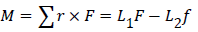
where and are measured the total force on the chest and the thighs respectively, and is 0.2 m (the length between the center of rotation of the lower back and the thighs, it is depends on the subject and measurement environments). Black bars mean the standard deviation of N=5 times measurement force values.
The variables and the estimation torque mathematical model were defined as Figure 5. The f was calculated two times larger than the practical force measurement value on the one side of the thighs.

Figure 5: Simplified lower back bending torque estimation model. Lower back bending torque M was calculated from (A) total force on the chest F and length from the lower back to the shoulder L_1, and total force on the thighs f and length from the lower back to the thighs parts L_2. Theoretically, the estimation torque M_e when the subject does not use the support device was calculated as M_e=L_1 mg sin θ. In addition, the calculated estimation torque M from the force measurement result was calculated as M=L_1 F-L_2 f.
Lower of the Figure 4 means that the M were distributed around the zero moment value and maximum value was about 1.88 Nm (standard deviation ± 0.81 Nm, N=5 experiments, 70° condition).
The value was 49 Nm/1.88 Nm=26 times smaller than with the support device comparing with the condition of without support device. At least, the subject's lower back bending torque could be relieved. It is main result of this study.
Figure 6 shows that real time force plot of A (chest), B (lower back), C (thighs) parts when the subject holds 100 N object and the proposed support device angle was set as 70°. The subject holds the 100 N objects at 58 sec and is holding the object until 200 sec. In this experiment, the subject was instructed to relax and not to use the backbone muscles as much as possible when holding the 100 N objects. The result of Figure 5 was calculated from all angle conditions of the real time force plots (force values were used at 200 sec point in Figure 6). From this result at 200 sec, the object + subject upper body weight was measured about 181.6 N at A part, and the total force of the thighs was measured about 455.8 N at C. As rotational torque, the two forces were cancelled each other by the proposed device (for example, M=L1F-L2F= 0.5 ⋅ 181.6 − 0.2 ⋅ 455.8 = 0.36 Nmit was small value comparing with 49 Nm (without device condition)).

Figure 6: Real time force plot result of A (chest), B (lower back) and C (thighs) parts when the subject holds 100 N object and the proposed support device angle was set as 70°. Horizontal axis shows the elapsed time and vertical axis shows the measured force values of A, B and C.
In addition, 190.6 N was measured at B part at 200 sec. This force was not rotational torque and it pushes the lower back to ventral direction. Almost all the cases, the lower back pushing force B was measured as same value with the chest part force value.
Above result means that though the proposed device could relieve the rotational torque as shown in Figure 5 (and the rotational torque was relieved by the anti-reaction force at C about 450 N in Figure 6), on the other hand, about 200 N pushing force to ventral direction at B part (Figure 6 blue line) was appeared. As the aim of the developed device, the system was developed to be able to relieve the rotational torque of the lower back bending load and it could realize by the proposed mechanism, however, about 200 N pushing force to B part and 450 N to C part became necessary at the same time.
Discussion
In this paper, another possibility of the external device's contacting position with the body in order to relieve the bending load of the lower back was discussed. By simplifying the mechanical structures and the touching positions to a human body, one of the solutions how to relieve the lower back bending torques was found and discussed by the proposed device. The proposed system does not have motor(s) or actuator(s), however, we analyzed how to relieve the bending load of the lower back by proposing a novel three points (A,B,C in Figure 1) support device.
The proposed system could relieve the lower back bending load, on the other hand, the heavy object load appears as pushing force to B and C parts. In such as care, logistic and agriculture fields, the bending load of the lower back for lifting a heavy object is said as a most significant problem and it has been a cause of lower back pains. In Figure 6, the 200 N and 450 N pushing forces is not the rotational bending force and since it is just pushing force, there is a possibility to reduce the pains on the skin by changing the B and C parts shape or mechanism.
Previously proposed external power assisting mechanisms would be able to support all load of the heavy object since the external device and actuator power undertake all load [17,28]. Typically the motor assisted previous power assisting devices can be categorized as two cases (Figure 7). (a) In the case of thigh and chest connected type power assisting device [Muscle suit type, 14], the actuator (Figure 7A, blue circle) push’s the thigh (B) and the belt connected chest (C) parts. It can realize the lifting movement via rotating the actuator (A). But, the actuator power assists only the hip joint rotation, the movement support of the lumbar spine segment movement could not assist. It generally generates a sense of discomfort. (b) In the case of thigh and abdomen connected system [HAL type, 14], the actuator (A) pushes the thigh (B) and the belt connected abdomen (E). It is good for the stability of the lumbar spine segment movement, but, it also generates the pain in the abdomen (E) area.

Figure 7: Two types of the previously proposed external power assisting mechanism. (a) Thigh and chest connected system and (b) Thigh and abdomen connected system.
On the other hand, our proposed device has been developed to pay attention how to protect the lower back bending load by using the principle of leverages (Figure 1) in order to absorb the rotational force by the frame [29-32].
Conclusions
In this paper, a lower back bending load relief mechanism for lifting heavy object by hands was proposed and the function was evaluated. In the wide range of fields such as care, logistic and agriculture, there are many tasks that are required to be bending the lower back for lifting heavy object by hand, and it has been a cause of lower back pain. Since the developed device is touched to three body points - (1) chest, (2) lower back and (3) thighs, the heavy object load by hands get on the chest part, and the rotational movement of the lower back would be relieved by the thighs anti-reaction force. In the timing, the lower back parts effects as the rotational center. 100 N load lifting experiment when 30,45,70° with the proposed device shows that the calculated rotational torque of the lower back takes a small value (at least < 2 Nm) comparing without the proposed device condition (49 Nm). Instead of cancelling the bending torque of the lower back, the proposed external device have to apply the object weight force to the lower back as pushing force. The mechanism would be useful to relieve the lower back rotational load when the subject holds a heavy load by the hands.
Acknowledgment
This work was supported by JSPS KAKENHI Grant Number 15K12598.
References
- (2014) Japan Ministry of Health. Business on disease outbreaks Survey.
- Kokubo A, Maezawa Y, Furusawa S, Uchida K, Baba H (2000) Prevention and countermeasures of low back pain as seen from the low back pain questionnaire survey of nursing staff. Journal of Japan back pain 6: 52-55.
- (2016) Japan Ministry of Health, Lower back pain measures.
- (2013) Japan Ministry of labour and welfare labor standards breau, Study group report on the revision and the spread of lower back pain prevention guidelies in the workplace.
- Matsuzaki T (2016) Introduce and its effect of long-term care that does not use “lift”.
- Fujimura T (1995) Present low-back pain problems. Nursing problems in geriatric ward and low-back pain measures. Digest of science of labour 50: 13-16.
- Inoue T, Fernie G,Santaguida PL (2000) Lower back loads during maneuvering tasks with lifting devices.Biomech 15: 243-254.
- Iwakiri K (2016) Ergonomic measures related to lower back pain the effect of the aid to support the position of anteversion.
- Nagasawa N, Watanabe H, Katsuhira J(2007) Analysis of the lumber stress of transferring motion by home care. Journal of architecture and planning 613: 81-87.
- Tanaka T, Imamura Y, Nara H, Shimizu S (2013) Smart SuitR Lite. The Second International Conference on Global Health Challenges, Lisbon, Portugal.
- Yamazaki N, Takahashi N (2004) Caregivers lumbar burden mitigation measures using the body surface length change. Journal of the Society of Biomechanisms17: 235-244.
- Tanaka T, Yoshinari T, Takizawa K, Nara H, Suzuki Y (2011) 3S Assist: The concept of KEIROKA Technology. Living life support medical welfare Engineering Society Joint Conference ABML University of Shibaura, Japan.
- http://activelink.co.jp/
- Kawamoto H (2005) Power assist method besed on phase sequence and muscle force condition for HAL. Advanced Robotics19: 717-734.
- Kobayashi H (2006) The Systems for Human Motion Support : Muscle suit and Active Walker. Journal of the Society of Biomechanisms 30: 184-188.
- Sano K, Yagi E (2011) Study on a Power Assist System for Overhead Harvesting/Slope Walking. The Japan Joint Automatic Control Conference 54: 213-213.
- Satoh H, Kawabata T, Tanaka F, Sankai Y(2010) Transferring-Care Assistance with Robot Suit HAL.JSME76: 227-235.
- Takigawa D (2014) Development powered suit for assisting transfer work.Housei University Graduate School Bulletin, Japan.
- Hara M, Sankai Y (2010) Research on HAL for Hip Joint Movement Support for Reducing Lumbar Load (Japanese). The 9th forum on Information Technology3: 547-548.
- Hanxing X, Xiaoyan L, Weillin L, Xiaoxiao L (2014) The Proceeding of the Research on Human Exoskeleton. International Conference on Logistics, Engineering, Management and Computer Science (LEMCS 2014), Amsterdam.
- Hozumi S, Tomoyoshi K, Fumihide T, Yoshiyuki S(2010) Transferring-Care Assistance with Robot Suit HAL. JSME 76: 227-235.
- Muramatsu Y, Suga H, Umehara H, Sato Y, Hashimoto T, et al. (2012) Development and Evaluation of a Muscle Suit to Assist Manual Labor: Assessment of Local Muscle Fatigue by NIRS (Wearable Robotics). Conference on Robotics and Mechatronics, Hamamatsu, Japan.
- Muramatsu Y, Kobayashi H (2014) Assessment of local muscle fatigue by NIRS-development and evaluation of muscle suit. ROBOMECH Journal 1: 19.
- Sato H, Nanka O, Kobayashi K, Matumura H, Hashimoto T, et al.(2012) Development and quantitative evaluation of the hip auxiliary muscle suit.JSME 78: 2987-2999.
- Yagi H, Sato M, Sano K, Mitsui R, Mabuchi H (2015) Verification experiment of electric power assist suit to support walking and lifting operations.JSME 80: 830.
- Imamura Y, Tanaka T, Suzuki Y, Takizawa K, Yamanaka M (2011) Motion-Based-Design of Elastic Material for Passive Assistive Device Using Musculoskeletal Model. JRM23: 978-990.
- Imamura Y, Tanaka T, Kaneko S, Yamanaka M, Takizawa K, et al. (2011) Design and Field Evaluation of Smart Suit Light for Care Motions based on Musculoskeletal Model(Wearable Robotics). Conference on Robotics and Mechatronics, Okayama, Japan.
- Umehara H, Kobayashi H, Hashimoto T, Suga H, Muramatsu Y, et al.(2012) Development of the Back Support Muscle Suit and the Peripheral System. Conference on Robotics and Mechatronics, Hamamatsu, Japan.
- Toda H, Sankai Y (2005) Three-dimensional link dynamics simulator based on N-single-particle movement. Advanced Robotics 19:977-993
- Toda H, Kobayakawa T, Sankai Y (2006) A multi-link system control strategy based on biological reaching movement. Advanced Robotics 20: 661-679.
- Toda H, Goto S (2013) Spine motion assist device. Japan patent JP2013-170577.
- Yamamoto H, Toda H (2016) Development a new mechanism of reducing the load of the waist. 34th anniversary annual conference of the Robotics Society of Japan meeting (Japanese), Yamagata, Japan.
Relevant Topics
- Electrical stimulation
- High Intensity Exercise
- Muscle Movements
- Musculoskeletal Physical Therapy
- Musculoskeletal Physiotherapy
- Neurophysiotherapy
- Neuroplasticity
- Neuropsychiatric drugs
- Physical Activity
- Physical Fitness
- Physical Medicine
- Physical Therapy
- Precision Rehabilitation
- Scapular Mobilization
- Sleep Disorders
- Sports and Physical Activity
- Sports Physical Therapy
Recommended Journals
Article Tools
Article Usage
- Total views: 13627
- [From(publication date):
October-2016 - Apr 02, 2025] - Breakdown by view type
- HTML page views : 12711
- PDF downloads : 916