Development of a Modified Extended Model Based Fault Detection and Diagnosis Approach
Received: 27-Oct-2022 / Manuscript No. DPO-22-73928 / Editor assigned: 31-Oct-2022 / PreQC No. DPO-22-73928 (PQ) / Reviewed: 14-Nov-2022 / QC No. DPO-22-73928 / Revised: 10-Feb-2023 / Manuscript No. DPO-22-73928 (R) / Published Date: 17-Feb-2023
Abstract
A supervisory system for space missions is critical due to the high risk of missions, the costs and the impossibility of adding redundancy. The model based fault detection approaches are of interest due to their highly responsive speed, robustness against disturbances and uncertainties and accuracy. Conventional model based methods have some drawbacks such as feasibility and applicability. In this paper, a Modified Extended Multiple Models Adaptive Estimation (MEMMAE) method is developed which keep both the advantages of the previous model based methods and take into account some limitations. This approach can be performed on various systems to detect and diagnose faults, with appropriate response speed and resistance to uncertainty and disturbances. By combining the recursive least square algorithm with the Extended Multiple Model Adaptive Estimation (EMMAE) method, the limitations of this method including simultaneous fault detection, diagnostics of failure cause and high processing volume are eliminated. The method is implemented on a spacecraft as a case study using the MATLAB/SIMULINK software and demonstrates that the responsive speed and accuracy of the proposed method is significantly much more effective and accurate than the previous method.
Keywords: Fault detection; Spacecraft; Reliability; Actuator; Model based; Applicable
Introduction
Due to the importance, complexity and cost of the space projects, increasing the reliability of system operation is vitally important. The main purpose is to consider various adverse conditions and takes the required action to attribute these faults or failures. Supervisory functions have a significant role to enhance reliability to detect undesired actions and subsequently perform the predesigned operations to maintain system performance.
The supervision function can be classified into three major groups; monitoring, automatic protection action and the Fault Detection and Diagnosis (FDD) process [1]. In the monitoring, process important variables checked and according to the predefined range, hazardous events are reported to the system management. The first two groups, only able to react after the occurrence a dangerous event or a long lasting steadily increasing fault. The FDD procedure measures variables, states and considering platform dynamics, detect dangerous or undesired defects.
From the past decades, FDD has been an interesting area of research in aerospace, process controls, automotive, manufacturing and the nuclear industry to improve systems reliability. Several methods developed in this field, which the substantial difference between them, are the information and knowledge to formulate the system application [2]. Detection can be obtained based on prior knowledge (model based design according to mathematical equations) or the data based approach using numerous observation and experimental tests (like black box models, neural networks) [3-5]. The data driven method does not require mathematical model development but, instead, monitors system behavior by measurement data and actual tests [6-8]. Data driven methods can be beneficial when the mathematical model of a physical system is complex and is not available. This approach needs a large volume of training data and is limited in extrapolation beyond the training data range. One of the data driven processes on the vehicle includes current spectrum analysis, vibration and acoustic analysis for motor fault identification [9,10].
This approach is also used in to detect gearbox faults by using an adaptive method [11]. Capozzoli, Laura and Khan applied a data driven method to commercial buildings to detect faults as duct fouling and excessive infiltration [12]. In Khalastchi and Kalech applied Sensor based Fault Detection and Diagnosis (SFDD), which uses the structural model data as well as the correlations between sensor measurements to detect and subsequently diagnose faults in a robot [13].
There is an increasing interest in the development of model based FDD methods as can be seen in the many papers submitted to the IFAC (International Federation of Automatic Control) [14,15]. The analytical redundancy is often according to these techniques: quantitative model based methods, parity relations, observers, Kalman filter and parameter estimations [16-19]. In a Kalman filter based method was performed for diagnosing both parametric and catastrophic faults in analog circuits [20]. Gliel employed a state observation to detect the fault in an industrial boiler [21].
In aerospace vehicles, mostly the fault detection and diagnosis process relies on hardware and sensor redundancy [22]. However, adding redundant hardware due to some main reasons as volume, weigh and cost limitations is not possible; supervision system through software has been obtained attraction in recent years. In cold gas thruster faults study during the Mars express spacecraft using the FDD method [23,24]. Kobayashi developed a diagnostic system based on a special Kalman filter and evaluate its application to in flight aircraft engine sensors [25]. Various applications of parameter identification regarding fault diagnosis based on the least squares method presented [26-27].
Another effective approach to detect and isolate actuator or sensor faults is the Multiple Model Adaptive Estimation (MMAE) method which was successfully implemented on various vehicles like aircraft and underwater vehicles [28,29]. The main advantage of the MMAE method compare to other FDD algorithms lies in its accuracy, fast responsiveness and robustness against parameter variations. In addition, the method enables the reconstruction of a correct state estimate even when an actuator or sensor fault occurs. With the combination of the MMAE method with the extended Kalman filter called EMMAE; this method is capable to detect the fault in the nonlinear dynamics platform.
In our previous article, the implementation of the EMMAE method on the spacecraft was evaluated and different common faults were applied on the reaction wheel as its actuator. Although the method was effective in detecting different faults and had high speed and proper accuracy, it was not applicable in certain conditions such as simultaneous failures and fault diagnostics due to requiring high processing hardware.
The objective of this paper is to develop the Modified Extended Multiple Model Adaptive Estimation (MEMMAE) method as a complementary method to solve the EMMAE mentioned problem. In this approach, the Recursive Least Square (RLS) methods were added to EMMAE methods to enhance the FDD capability to detect faults in all critical conditions using conventional hardware. Different actuator faults are applied and the method performance is evaluated. Furthermore, the ability to determine of dynamics states on a nonlinear system in even fault conditions is discussed.
The paper is organized as follows; section 2 deals with the description of the Attitude and Control Subsystem (ADCS) of spacecraft, its equations and common faults on the spacecraft during its mission. The MEMMAE method, mathematical equations, fault detection performance in various crucial cases using Simulink/Matlab software are provided in section 3. Finally, paper conclusions are presented in section 4.
Materials and Methods
System description
Satellite attitude and control: The Attitude and Control Subsystem (ADCS) is one of the main subsystems in the satellite, which is responsible to control the platform to the desired attitude under persistence disturbances and uncertainties. This subsystem consists of different units with specific functions. Presence of numerous components as well as complex algorithms has made it the most important and challenging subsystem.
The schematic for a closed loop process of the ADCS subsystem during satellite mission is presented in Figure 1.

Figure 1: Schematic of a satellite attitude control subsystem.
Based on this structure, the controller using sensor data and platform attitude generated the required command and sends it to actuators. By operation of actuators, the platform excited and its attitude changed. Various sensors such as sun sensors, magnetometers and gyro measure this change and send these measurements to the attitude determination unit. During this process, the health monitoring unit plays a significant role. This unit can detect and diagnose faults. In the case of a fault occurrence, model based methods can be utilized to detect, diagnose and isolate the problems. In this paper, our focus is on the detection and diagnosis of different faults on the actuators based on model based algorithms.
Typical actuator fault cases
By increasing knowledge about satellite components and their behavior in the space environment, usage of the FDD approaches increased markedly. Due to design and mass restrictions, advanced monitoring techniques can compensate the absence of hardware redundancy. Figure 2 shows the failure breakdown for the different spacecraft subsystems.

Figure 2: Spacecraft subsystems affected.
The most percentage of failure occurrence is related to ADCS in particular its actuators. Actuators consist of moving mechanical parts and are subject to unanticipated faults/failures like cold solder joint, minute particles or massive temperature fluctuations.
Various actuators are employed base on the satellite missions as Reaction Wheel (RW), Momentum Wheel (MW), cold gas thruster and magnetic torque but the most common actuator to provide pointing is RW. A RW consists of a flywheel attached to a brushless DC motor. Notably, that at least three RWs are required for fully actuated attitude control.
Results And Discussion
Table 1 describes some of the recent momentum/reaction wheel failures in space missions concerning the importance of the monitoring system.
| Spacecraft | Cause of anomaly | Year |
|---|---|---|
| Radarsat-1 | 2 pitch MWs failed | 1999, 2002 |
| ISS | 1 CMG failed on June 8 | 2002 |
| Hayabusa | X and Y axis RW failed on July 31 and October 2, respectively | 2005 |
| Fuse | Final RW required for accurate pointing failed | 2007 |
| TIMED | Single RW failure | 2007 |
| Dawn | Two RW failures due to excessive friction development | 2010, 2012 |
| Kepler | Two RW failures disabled accurate positioning/data collection | 2012, 2013 |
Table 1: Summary of on orbit failure of RWs.
The main reason for failures in RW can be classified into four main groups:
• Due to faulty electronics driver and power supply. The wheel fails to respond to any control signals and decelerates slowly or holds its position. This can cause zero or undesired torque outputs from the wheel.
• Caused by the friction between rotor and stator, marginal failure of the bearings leads to do not apply desired control commands.
• Incipient faults, caused by friction due to aging or time varying temperature, etc. can lead to undesired acceleration or deceleration of the wheel. Consequently, the wheel would generate a biasing torque even in the event of zero commanded torque.
• Intermittent time varying faults in the motor current or fault in the bus voltage can lead to continuous increase/decrease in the wheel speed. This can lead to undesired reaction torques generated by the wheel regardless of the commanded torque by the controller.
Mathematical models
Euler equations are used to model the dynamics of the spacecraft, with respect to an inertial coordinate system (I). The reaction wheels are used as excitation actuators. The attitude dynamics of a rigid simulator are given by Euler's equation:

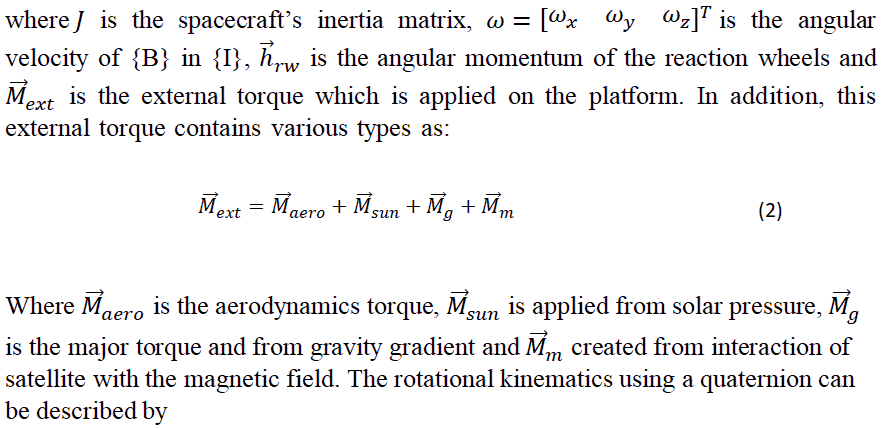
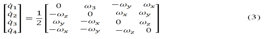
Where q=[q1q2q3q4]T are the quaternions. The quaternion is defined as a vector in the following way

The mathematical model of a reaction wheel is similar to the model of a DC motor, in which the flywheel adds to increase the total inertia and provide much more torque. In the friction model considered here, the viscous friction, Coulomb friction and the friction of Stribeck are included. The equation describing the friction torque is as:
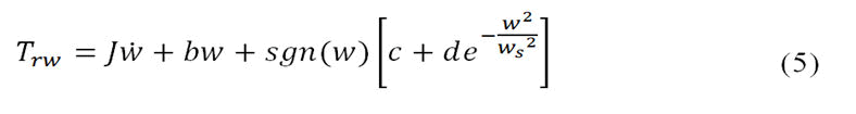
Where Trw is the motor torque, the wheels and rotor inertia is J, b is the coefficient of viscous friction; c is the coulomb friction torque, d is the starting torque, w is the angular velocity of the wheel and ws is known as Stribeck speed.
Modified EMMAE method
The developed method is according to completing the EMMAE method and presents an innovative technique to solve its limitations. Despite the many advantages of the method, due to the structure and equations of this method, some limitations were also observed in software implementation.
• The method cannot detect faults simultaneously. According to the probability equation, which assigns a probability to different states of failure, the probability is divided between different states. In other words, if faults occur in series, they can detect, but in the event of parallel and simultaneous faults, only one actuator is identified as faulty.
• Regarding the ability of diagnostics, although it is possible in programming and software, due to the many causes of failure and a large number of actuators in different systems such as spacecraft, a very high processing volume is required. In the diagnostics process, a large number of EKFs are executed in parallel, which in hardware implementation cannot perform practically.
• The sensitivity of the method is the responsibility of the programmer. The system can detect the error with the least deviation from the desired value and can remain reluctant with a high difference. Therefore, it requires a high level of experience in hardware implementation.
The main approach of this method is to create the ability to implement practically on various dynamic systems, including spacecraft. The process of implementing the MEMMAE method is explained in Figure 3.

Figure 3: The MEMMAE method scenario.
This technique consists of two main parts; fault detection and fault diagnostics.
In the detection part, using the Recursive Least Square (RLS) method, faulty actuators are identified. In addition to high accuracy and responsive speed, it can detect faults simultaneously.
In the second part, the EMMAE method is used and the cause of the fault is determined. Each faulty actuator may be faced with a defect for a variety of reasons, which are recognized in this section. A set of EKFs corresponding to different causes runs parallel and the failure cause is determined based on the probability method.
The valuable point in this scenario is the identification of the faulty actuators at the first step. This initial identification causes that only the subsystem concerning actuators become activate, resulting in a significant decrease in the number of EKFs. Other advantages of this method are robustness against uncertainties and disturbances of the environment. Defining the level of sensitivity based on practical and software implementations can provide good reliability in addition, adding RLS technique leads to improve performance and make the ability to run this approach on conventional hardware.
Step 1: Fault detection
The Recursive Least Square (RLS) is one of the most well-known algorithms used in adaptive filtering, system identification and adaptive control. Its popularity is mainly due to its fast convergence speed, which is considered optimal in practice. In this method, the estimated parameters are computed recursively over time: By converting problem to the regression form such that Ax=B, suppose we have an estimated xt-1 at iteration t-1, then recursive identification aims to compute a new estimated xt by a simple modification of xt-1 when a new observation becomes available at iteration t. The RLS approach starts from a slightly modified loss function:
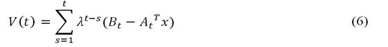
Where and are known matrix from estimation problem and λ forgetting factor. The main approach of the algorithm is finding x to reduce loss function. The RLS algorithm can be represented by equation 7 as follows:

Where α (t) is an estimation error at the moment t and λ is forgetting factor, If λ is set to values slightly smaller than 1 (λ=0.99 or λ=0.95) for increasing t past observations are discounted. The assumed λ becomes smaller, the quicker information obtained from previous data will be forgotten. Being initialized with P(0)=δ-1I, where δ is a small positive constant. The advantage of the RLS algorithm is that there is no need to invert matrices, in addition to its saving computational power.
Step 2: Fault diagnostics
One effective scenario for diagnostics faults on actuators or sensors is the EMMAE method as shown. It monitors the system based on a bank of Extended Kalman Filters (EKFs) running in parallel, which each of these EKFs corresponding to the specific status of the system.
A hypothesis algorithm by comparing the residuals of each EKFs estimation and system outputs provides a conditional probability to each fault hypothesis.
The main advantage of the EMMAE method attributes the responsiveness to parameter variations, leading to fault isolation more quickly comparing other methods. The scenario also reconstructs and prepares the correct state estimation under the occurrence of actuator or sensor fault. This capability is based on the summing of each EKF estimated and weighting them using its corresponding probability.
EKF design process: The EKFs are designed based on a set of continuous nonlinear differential equations. The prediction phase of the estimation can be determined as:
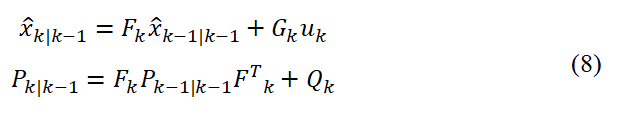
Where Fk is the continuous system dynamics matrix, Q the covariance of the process noise is G is the control input model and P is the covariance matrix. In the following, the update phase is presented.
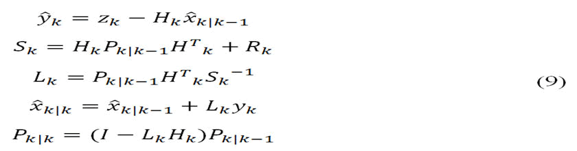
Where R is the covariance of the observation noise and the H is the observation model.
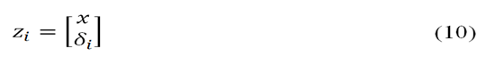
EKF reproduction based on the faulty actuator: The state vector of the ith is augmented to monitor the actuator faults. This stated is added to the estimate during EKF estimation. Therefore, the state vector for each filter i is:
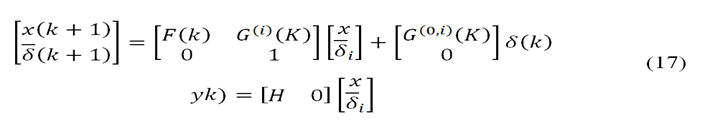
The augmented state vector leads to the following state space equations.
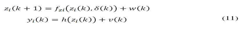
Where,


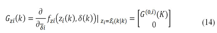
With G(0,i) representing the matrix G with its ith column set to zero. The linearization of the measurement matrix is:
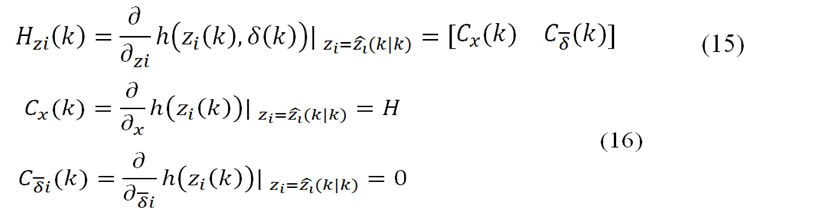
Using the above equations, the linearized system evaluated at each sampling time can be shown as:
Hypothesis testing algorithm: A hypothesis testing algorithm uses the residuals and the state error covariance matrix from each EKF to assign a conditional probability to each fault scenario. The estimated state vector of the system is the sum of the state vector of each EKF weighted by its corresponding probability,
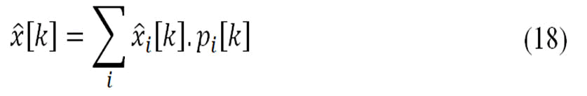
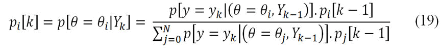
Where x̂i[K] the state estimate is computed by the EKF that assumes the fault scenario θi. The index i cover all the fault scenarios implemented, including the no fault case. The fault probability pi[k] can be expressed as the posteriori conditional probability pi[k]=p(θ=θi,Yk) the probability that the actual plant can be categorized in scenario θi given the sequence of the last measurements Yk.
By examining the probabilities computed by equation 19, we can determine the health status of the system, either in the no fault case or in an actuator/sensor failure case:
Since a fault may occur at any time, regardless of which actuator may fail, we decide to assign the same probability to all the scenarios, i.e. p[θ=θi]=1/N for j=1, N.
We now derive an explicit formula for the term p[y=yk|(θ=θi, Yk-1)] which corresponds to the probability of obtaining the measurement data yk at time tk=KTs. The probability density is chosen to be a Gaussian function with its characteristic bell shaped curve according to the following formula:

Where,
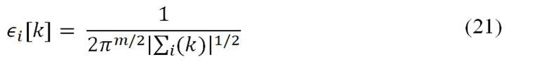
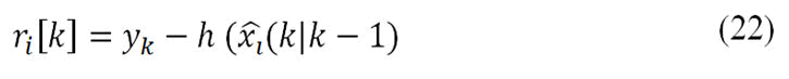
Where term |…| denotes the determinant of the matrix m represents the measurement dimension and Σi(k) is the residual covariance matrix calculated at a time step by the ith EKF. The term ri[k] corresponds to the residuals of the ith EKF when the measurement update step occurs according to the equation.
Simulation results of MEMMAE method
In order to evaluate the performance of the developed method, this technique is applied on a satellite. Mostly, the satellite uses 3 reaction wheels to control its attitude. The purpose of this method is to detect and diagnostics various faults during the satellite mission (Table 2).
Six different failure modes can cover all failure states. These fault modes can be described as:
| Fault mode | Explanation |
|---|---|
| 1 | RW1 |
| 2 | RW2 |
| 3 | RW3 |
| 4 | RW1-RW2 |
| 5 | RW1-RW3 |
| 6 | RW2-RW3 |
Table 2: The main features of defined maneuver (Detection test).
Also, the most common reason for faults on the RW is related to the viscous changes as well as the performance characteristics of the DC motor. The developed algorithm should be able to estimate the cause of the fault, which is mainly due to these two parameters.
First, a slew maneuver without any fault occurrence is performed to ensure about simulation process and designed PID controller on the platform (Figure 4). The initial condition (0, 0, 0) is considered and the platform is excited to achieve the desire attitude degree that is (60, 40, 80).

Figure 4: Satellite attitude maneuvered.
As can be observed a 3 axis maneuver was implemented on the platform reaching the desired attitude below 30 sec using three reaction wheels as actuators. Also, the satellite angular velocities on the three axes are presented (Figure 5).

Figure 5: Satellite angular velocities.
The angular velocity increased during the applied maneuver and provides sufficient stability at the end of the maneuver by reaching the desired attitude. The change of actuator velocity is also illustrated to describe this maneuver in detail (Figure 6).

Figure 6: Reaction wheel angular velocity.
It is evident that platform momentum remains constant during the mission; hence the satellite angular velocity and actuators are applied in the opposite direction. The maximum actuator velocity is under 2500 rpm and the difference between axes measurements are based on the platform inertia. After ensuring about developed attitude controller performance and mission simulation without occurrence fault, we start to apply different types of actuator faults and assessment the MEMMAE performance to detect the faulty actuator.
Case 1: Fault detection process
As indicated, the proposed method consists of two parts that run subsequently; fault detection and diagnostics. In the first step, which is based on the RLS algorithm, the defect or fault occurrence in the actuators is estimated.
To investigate the algorithm performance, a sinusoidal maneuver is designed and operators subsequently encountered different faults. The main features of this maneuver are defined as:
As presented in Table 3, various faults are applied to the actuators during the maneuver. To study the ability of the developed method to detect simultaneous faults, these types of failures also occurred in this test. The changes of RW speeds during this test are presented in Figure 7.
| Fault mode | Faulty actuators | Time |
|---|---|---|
| 0 | No fault | 0-15 |
| 1 | RW1 | 15-30 |
| 0 | No fault | 30-45 |
| 4 | RW1-RW2 | 45-60 |
| 0 | No fault | 60-75 |
| 2 | RW2 | 75-90 |
| 0 | No fault | 90-105 |
| 6 | RW2-RW3 | 105-120 |
| 0 | No fault | 120-135 |
| 0 | No fault | 135-150 |
Table 3: The main features of defined maneuver (detection test).

Figure 7: Reaction wheel speed during the fault detection test.
As can be seen, due to sinusoidal maneuvering, the wheel changes are sinusoidal. In this test, the error is assumed a complete failure in which no electric current is applied to the RWs. Due to frictional torque, the speed of the motors decreases after the cutting of the currents and this is evident in the changes of speeds. The estimated results of the method are provided in Figure 8.

Figure 8: The fault detection results of the AEMME method.
The developed method can identify the occurred faults accurately. The algorithm and the predefined (blue line) recognize all fault modes and detected (red line) results follow each other. The maximum time to detect a fault is about 3 seconds, which should be considered. After this period, the monitoring system must make the required decision. Modes 4 and 6 are related to simultaneous failure, which the algorithm has been able to accurately detect.
Case 2: Fault diagnostics process
After ensuring the performance of the fault detection step in the previous test, the fault diagnostics and the causes of the defects are examined in this test. In this test, a pointing maneuver in which the physical characteristics of a RW change, are simulated. The purpose of this test is to detect the faulty RW and in the second step determination of the cause of this failure. The predefined features of this test are as (Table 4 and Figure 9).
| Title | Explanation |
|---|---|
| Desire attitude | (40-60-80) deg |
| Faulty RW | RW1 |
| Faulty mode | 1 |
| Cause of defect | Viscose parameter (b) increase from 4e-06 to 4e-04 |
Table 4: The main features of defined maneuver (Diagnostics estimation).

Figure 9: The Euler angles during the diagnostic detection test.
As can be seen, both maneuvers can achieve the desired points. Due to the higher frictional torque, the arrival time in the faulty test is longer. This interception delay is more distinguished in wheel 1. The change of RW speed during this test is reported in Figure 10.

Figure 10: Reaction wheels speed during the fault diagnostics test.
The presence of frictional torque reduces the required torque and has a direct effect on RW speed. Due to the coupling dynamics of the spacecraft, this lack of torque supply also affects the motion of other wheels. The difference between the speed of RW1, in the healthy and defective condition, is significant. The result of the MEMMAE method during this test is provided as (Figure 11).

Figure 11: The fault detection and diagnostics results of the MEMME method.
The algorithm was able to detect the faulty RW in 2 seconds. During this time, the second part of the algorithm is inactive. As can be seen, the probability of defects in both possible cases is 50%.
After two seconds and an accurate estimation of the faulty actuator, the second part is activated and can determine the cause of the fault. Change the viscose parameter is the cause of the specified failure.
Case 3: Compare results with EMMAE
To compare the efficiency and performance of the developed with the previous method, a scenario has been designed to show the capabilities and improvements of the proposed method. The main features of this test are defined as Table 5.
| Fault mode | Faulty actuators | Time |
|---|---|---|
| 0 | No fault | 0-14 |
| 1 | RW1 | 14-28 |
| 0 | No fault | 28-44 |
| 6 | RW1-RW2 | 44-55 |
Table 5: The main features of defined maneuver (Evaluation test).
As can be seen, both simultaneous failure and single failure are considered for evaluation. The changes of RW speeds during this test are presented in Figure 12.

Figure 12: Reaction wheel speed during the evaluation test.
To compare the results of the two methods, sinusoidal maneuvers are applied. After deactivating the wheels, their speed decreases due to friction. The results of the two methods can be observed in Figure 13.

Figure 13: The fault detection results of the EMMAE and MEMMAE method.
Due to the inability of the EMMAE method to fault diagnostics terms, only the fault detection mode is compared with each other. Both methods correctly identify the first applied faults during 14-278’s. notably; the proposed method detects the fault more quickly. Simultaneous failure of actuators (RW2, 3) occurred between 44 and 55 seconds. As can be seen, the previous method identified only one of the actuators, but the MEMMAE method correctly identified both failures. A detailed comparison of the test results is provided in Table 6.
| Fault Mode | Features | EMMAE | MEMMAE |
|---|---|---|---|
| Fault 1 14-29 | Responsive time | 17.6 | 14.5 |
| Faulty actuators | RW1 | RW1 | |
| Cause | - | K | |
| Fault 2 44-55 | Responsive time | 45.3 | 44.2 |
| Faulty actuators | RW3 | RW2-RW3 | |
| Cause | - | K |
Table 6: The detailed comparison results (evaluation test).
The proposed method has a more responsive speed compare previous, method. In addition, detection fault simulation is a remarkable advantage over the EMMAE method.
Conclusion
In this paper, different fault detection and diagnosis methods were discussed and due to high reliability, capability to detect faults in the presence of various uncertainties, fast detection process and the possibility of practical implementation, the Extended Multiple Model Adaptive Estimation (EMMAE) Method were selected. Despite the many capabilities of this method, there were limitations in this method, which the main purpose of this article is to modify. The MEMMAE approach was presented and the steps for its implementation were stated along with the equations. Using this method, limitations of the EMMAE method, including unable to fault diagnostics, simultaneous faults on actuators and high processing volume in this method were eliminated. The capability of this method was evaluated by performing various tests using MATLAB software and its results compare with the previous method. By conducting various tests, it was determined that the algorithm can detect different faults of the spacecraft actuators in different modes and can be used practically. The study of robustness against disturbances and uncertainties as well as a combination of the EMMAE method with other estimation algorithms will be considered in the next article.
Authors' Contributions
In this paper, we report on model based fault detection approaches. In this work, Modified Extended Multiple Models Adaptive Estimation (MEMMAE) method is developed which keep both the advantages of the previous model based methods and take into account some limitations of that.
References
- Isermann R (2005) Model based fault detection and diagnosis status and applications. Annu Rev Control 29: 71-85. [Crossref] [Google Scholar]
- Katipamula S, Brambley MR (2005) Methods for fault detection, diagnostics and prognostics for building systems a review, Part I. Hvac Res 11: 3-25. [Crossref] [Google Scholar]
- Yu X, Jiang J (2015) A survey of fault tolerant controllers based on safety related issues. Annu Rev in Control 39: 46-57. [Crossref] [Google Scholar]
- Carvajal-Godinez J, Guo J, Gill E (2017) Agent based algorithm for fault detection and recovery of gyroscope's drift in small satellite missions. Acta Astronaut 139: 181-188. [Crossref] [Google Scholar]
- Anwar S, Niu W (2014) A nonlinear observer based analytical redundancy for predictive fault tolerant control of a steer by wire system. Asian J Control 16:321-334. [Crossref] [Google Scholar]
- Said M, Abdellafou Kb, Taouali O (2020) Machine learning technique for data driven fault detection of nonlinear processes. J Intell Manuf 31: 865-884. [Crossref] [Google Scholar]
- Gao T, Sheng W, Zhou M, Fang B, Zheng L (2020) MEMS inertial sensor fault diagnosis using a CNN based data driven method. Int J Pattern Recognit Artif Intell 34: 2059048. [Crossref]
- Talebi HA, Khorasani K (2007) A neural network based actuator gain fault detection and isolation strategy for nonlinear systems. IEEE Conference Decision Control 46: 2614-2619. [Crossref] [Google Scholar]
- Virtic M, Abersek B, Zuperl U (2008) Using of acoustic models in mechanical diagnostics. J Mech Eng 54: 874-882. [Google Scholar]
- Belsak A, Flasker J (2008) Vibration analysis to determine the condition of gear units. J Mech Eng 54: 11-24.
- Capozzoli A, Lauro F, Khan I (2015) Fault detection analysis using data mining techniques for a cluster of smart office buildings. Expert Syst Appl 42: 4324-4338. [Crossref] [Google Scholar]
- Khalastchi E, Kalech M (2018) A sensor based approach for fault detection and diagnosis for robotic systems. Auton Robots 42: 1231-1248. [Crossref] [Google Scholar]
- Cho S, Gao Z, Moan T (2016) Model based fault detection of blade pitch system in floating wind turbines. J Phys Conf Ser 753: 092012 [Crossref] [Google Scholar]
- Skliros C, Esperon Miguez M, Fakhre A, Jennions I (2019) A review of model based and data driven methods targeting hardware systems diagnostics. Diagnostyka 20: 3-21. [Crossref] [Google Scholar]
- Zhao X, Zhang L, Ouyang D, Jiao Y (2009) Deriving all minimal consistency based diagnosis sets using SAT solvers. Prog Nat Sci 19: 489-494. [Crossref] [Google Scholar]
- Venkatasubramanian V, Rengaswamy R, Yin K, Kavuri SN (2003) A review of process fault detection and diagnosis: Part I: Quantitative model based methods. Comput Chem Eng 27: 293-311. [Crossref] [Google Scholar]
- Li XL, Xie Y, Bi D, Ao Y (2013) Kalman filter based method for fault diagnosis of analog circuits. Metrol Meas Syst. [Google Scholar]
- Shim D, Yang C (2010) Optimal configuration of redundant inertial sensors for navigation and FDI performance. Sensors 10: 6497-6512. [Crossref] [Google Scholar] [PubMed]
- Patton R, Uppal F, Simani S, Polle B (2010) Robust FDI applied to thruster faults of a satellite system. Control Eng Pract 18: 1093-1109. [Crossref] [Google Scholar]
- Falcoz A, Henry D, Zolghadri A (2010) Robust fault diagnosis for atmospheric reentry vehicles: A case study. IEEE Trans Syst Man Cybern Part A Syst Hum 40: 886-899. [Crossref] [Google Scholar]
- Kobayashi T, Simon DL (2006) Hybrid Kalman filter approach for aircraft engine in flight diagnostics: Sensor fault detection case. J Eng Gas Turbines Power 129:746-754. [Crossref] [Google Scholar]
- Ward DG, Monaco JF, Bodson M (1998) Development and flight testing of a parameter identification algorithm for reconfigurable control. J Guid Control Dyn 21: 948-956. [Crossref] [Google Scholar]
- Alireza A, Ghasem S (2020) Application of a model based fault detection approach on a spacecraft. Int J Reliab Risk Saf Theory Appl 3:19-26. [Crossref] [Google Scholar]
- Moradi R, Alikhani A, Jegarkandi MF (2017) Reducing the effects of inaccurate fault estimation in spacecraft stabilization. J Aerosp Technol And Manag 9: 453-460. [Crossref] [Google Scholar]
- Cowen R (2013) The wheels come off Kepler. Nature 497: 417-418. [Crossref] [Google Scholar] [PubMed]
- Murugesan S, Goel PS (1987) Fault tolerant spacecraft attitude control system. Sadhana 11: 233-261. [Crossref]
- Sharifi G, Zabihian E (2020) An effective approach to identify the mass properties of a satellite attitude dynamics simulator. Aust J Mech Eng 18: 245-254. [Crossref] [Google Scholar]
- Ousaloo HS, Sharifi G, Akbarinia B (2021) Extended validation of a ground based three axis spacecraft simulator model. Proc Inst Mech Eng G: J Aerosp Eng 235: 151-170. [Crossref]
- Chen RH, Speyer JL (2004) Sensor and actuator fault reconstruction. J Guid Control Dyn 27: 186-196. [Crossref] [Google Scholar]
Citation: Alikhani A, Sharifi G (2023) Development of a Modified Extended Model Based Fault Detection and Diagnosis Approach. Diagnos Pathol Open 8:215
Copyright: © 2023 Alikhani A, et al. This is an open access article distributed under the terms of the Creative Commons Attribution License, which permits unrestricted use, distribution and reproduction in any medium, provided the original author and source are credited.
Select your language of interest to view the total content in your interested language
Share This Article
Open Access Journals
Article Usage
- Total views: 2352
- [From(publication date): 0-2023 - Nov 14, 2025]
- Breakdown by view type
- HTML page views: 1909
- PDF downloads: 443