Research Article Open Access
Design and Project of Masonry Vaults by Software based in Geometry Methods
Justo García-Sanz-Calcedo*, Manuel Fortea, Jose Luis Canito and Antonio Manuel Reyes
University of Extremadura, Spain
- *Corresponding Author:
- Justo García-Sanz-Calcedo
University of Extremadura, Spain
Tel: 34-927-25-70 00
E-mail: jgsanz@unex.es
Received Date: August 24, 2015; Accepted Date: September 15, 2015; Published Date: September 23, 2015
Citation:Calcedo JGS, Fortea M, Canito JL, Reyes AM (2015) Design and Project of Masonry Vaults by Software based in Geometry Methods. J Archit Eng Tech 4:152. doi:10.4172/2168-9717.1000152
Copyright: ©2015 Calcedo JGS, et al. This is an open-access article distributed under the terms of the Creative Commons Attribution License, which permits unrestricted use, distribution, and reproduction in any medium, provided the original author and source are credited.
Visit for more related articles at Journal of Architectural Engineering Technology
Abstract
This paper reports on an investigation on vaulted ceilings aimed at seeking connections between the geometry of such architectonic elements and their structural behaviour. A search for the balance of forces acting through such elements is put forward, upholding on the Limit Analysis Theory. Graphically, the element's security limits are evaluated according to the forces’ trajectory distance through the vault or dome shapes. A simulation of the application of this graphical method on three equally dimensioned square-based types of vaults is presented (namely barrel, groin and dominical vaults).
The groin vault is the lightest (1.514 N/m2) and that with the lowest Concavity Factor (1.14), while the dominical vault stands as the heaviest (2.244 N/m2) and shows the highest Concavity Factor (2.07). On another note, the barrel type is only supported by its sides (4.610 N horizontal thrust applied on each one), the groin vault on its four corners (horizontal thrust 3.102 N, diagonally directed) and the dominical type on its four sides (1.524 N horizontal thrust on each).
Despite stress values on the three vault types are low, a couple of points ought to be accounted for. The maximum stress on the groin vault is 0.03 N/mm2 with a significant increase up to 0.34 N/mm2 as the edges are approached. The maximum radial stress –transmitted to the supporting elements- on the dominical vault is 0.03 N/mm2, although a parallel-to-the-supports ring stress appears (whose intensity depends on proximity to vertical position as related to the supports) ranging up to 0.17 N/mm2, quite higher than the radial stress. Maximum work stress is not the defining value in order to guarantee stability for this element.
Keywords
Vault; Dome; Geometry; Strains
Introduction
This survey addresses the close relation between the geometry of masonry vaults and their structural behaviour [1]. As arches and domes are considered a type of vault, all the vaulted structures are taken into consideration. All of them are masonry structures, made of a discontinuous isotropic material, either stone or brick-made, and formed by a group of small elements if compared to the global structural dimensions [2]. They are very common in the region of Extremadura (Spain) [3] and are mainly linked to monumental purposes as well as to residential and agricultural applications [4,5]. These elements are typically featured by a singular construction technique: they are built without false work, i.e. without an auxiliary structure helping throughout the construction process [6]. This particular attribute sets Extremadura and the Portuguese area of Alentejo as worldwide references [7].
New technologies applied to construction techniques derived from the industrial revolution, such as steel and concrete, have arrogantly monopolized the market, in a similar way petroleum did as referred to the energy industry [8]. However, a new interest for masonry has been seen to emerge in the last decades, undoubtedly influenced by the late increase of restoration and rehabilitations, activities with growing relevance due to the economic crisis [9]. Provided this type of structure works at low stress regimes, its frailness is not conditioned by material resistance, but by spatial configuration, shape and geometry [10].
The first book that rigorously gathers the plastic theory of steel frames calculus [11] was published. It condensates and ads up all the material the Cambridge Team had achieved for the last decade and contains the first reference ever to the Limit Analysis Fundamental Theorems in a calculus publication. The Fundamental Theorems were demonstrated by Gvozdev, but rather darkly published in the Moscow Science Academy Record. They went unnoticed and were rediscovered by Praguer's Team by the early 50s. The application of these theorems to steel frames allowed to set the plastic calculus (which had been used in England since 1948 -the year the British regulations added a clause to account for plastic calculus) in a precise framework.
Heyman guessed that the theorems could also be adapted to masonry and brickwork, and even to wood structures. He proved the new paradigm could be applied to any ductile structure. In fact, the main corollary of the Safe Theorem of Limit Analysis stands for what Heyman refers to as the “equilibrium approach”, by which the analyst shall only use two or three fundamental equations, namely those relating equilibrium and material. His approach to equilibrium has already been used by eminent engineers guided by such structural intuition [12]. Even though this is a key theory for any architect or engineer working on structures, it was also seen to be useful for historians working on architecture, engineering and construction, as well as for anyone who would like to deepen on the development of structural forms. His manuscript entitled “The Stone Skeleton” was published in 1966 and was a clear and original approach to the adaptation of the plastic theory to the field of traditional masonry construction. Following Praguer's suggestions, he stated that the Fundamental Theorems could be translated into these (apparently so different) structural types by merely assigning certain properties to masonry [13]. After his first article in 1966 more than thirty other ones and several books have followed up to date, in which Professor Heyman applied the modern theory to the study of the basic structural elements of masonry construction (vaults, domes, buttresses, towers, steeples, etc.). In fact, his interpretation of gothic theory yields to conclude the debates on the structural behaviour of the cathedrals studied by theorists since middle 19th century [14]. The Plastic Theory is based on Gvozdev's Principles, which establish that only three types of equations shall be stated [15] (i) the equilibrium equations; (ii) the yield strength conditions (no internal stress must be higher than the material stress limit); and (iii) equations to account for the fact that a deformation mechanism must take place during structural collapse. Gvozdev proved three theorems based on the application of the three conditions, namely those of Unicity, Insecurity and Security [16].
Methodology
In order to meet these goals a methodology based on the Limit Analysis Theory consisting of a systematic analysis of the arches, domes and vaults' structural behaviour was implemented. Results were further used to assess the relation between geometry and behaviour of the structures as well as to quantify such degree of correlation. This methodology is unprecedented. Even though complex brickwork and masonry geometry are traditionally reported to be related to resistance, the methodology involved was based on particular “tricks” to determine the dimensions of elements such as straps or buttresses rather than on specific graphical techniques. The present work is focused on the analysis of a set of arches, domes and vaults classified as curved, double curved and complex elements. Barrel vaults and their derivatives are included in the former group. The second category stands for radial domes, 'Extremeñan' vaults and its derivatives. Finally, the last category includes ribbed vaults in general, designed with ridge ribs and civary. Different data sets sorted by origin and nature of the element were achieved for each of the analyzed items. Information was then comparatively assessed in search for constant parameters or behaviour trends.
The most famous and simple vault is that of semi cylindrical barrel, which is formed by a linear and continuous element whose upper part is a semi cylinder supported on two parallel walls [18]. The dome membrane has a lower surface (intrados), a visible cylindrical shape, whereas the upper surface (extrados) is the hidden side. It is usually more irregularly shaped, and it holds either another floor or the roof. This vault can be dissected into a set of thin parallel contiguous arches similar to slices. Vault analysis can be simplified by focusing on only one of those small arches and further computing the sum of that and the remaining ones. Let us then consider a barrel vault sliced into one-meter-width segments. The analysis of one of those arches would yield the results on the vertical and horizontal thrust supports. It might therefore be assumed that these results are coincident to the vault supports for each linear meter. However, an arch is not a onedimensional element, but it is also described in terms of edge depth and thickness. Three dimensions provide structural volume and, depending on density, net weight. This arch-slicing technique can be extended to any other type of vault. The single groin vault is the intersection between two semi cylindrical barrel vaults. If divided into slices, arches do not rest on the supports as in the former case, but on the groin, merging in pairs, one for each barrel vault. However, the groin cannot be dimensionless if it collects stresses since it would imply receiving infinite stress. Instead, it must be an arch spanning from one groin to the other one, passing through the centre, where it crosses the other groin. Dominical and ribbed vaults can be segmented in arches which may themselves rest on other ones. Segments should be symmetrical to the central axe, traversed by the line of force. Coplanar lines of force that are contained in the midsection might act as a symmetry axe. This way, segments can be divided into the three following types:
a) Parallel-sided segment: Barrel vaults and its derivatives produce the simplest slice, with parallel sides and constant width. It is a section of the vault extended through the third dimension with a constant value for each point. It is a fixed width arch with a central symmetry plane.
b) Converging-sided segment: Hemispheric domes and its derivatives produce a wedged slice, consisting of a section of a third-dimension extended dome with a variable value. Its width maximizes at its support and minimizes at the keystone, with a similar central symmetry plane. Wedge-shaped converging sides can be decomposed from the fan vault. In this case, the minimum and maximum slice widths lay at support and keystone, respectively.
c) Non-coplanar axe segment: Spiral staircases and helicoids can be decomposed in segments, but such elements have no symmetry axe, nor they have a symmetry plane. Accordingly they cannot produce coplanar lines of force. Besides the gravitational force and the thrusts, a rare force operates for this particular case, namely the centrifugal force, which sets forces to undergo a path different from that of the maximum slope. Coplanar axe segments are traversed by a force line. This line is also referred to as the thrust line, and is the geometric place where the resulting force is located within a given system of sectioning surfaces. Consider now a single half of a symmetrical arch. For this semi-arch to be balanced under its own weight, a horizontal force in the keystone is needed, which is provided by the other semi-arch. The force line starts right where the other semi-arch’s horizontal force acts. The vertical loads corresponding to each section of the arch add up to such force. This way, the force line is defined as the set of geometric points of the resultant vector on every section of the semi-arch.
Results
Carybo is a digital tool for the structural calculation and analysis of masonry and brickwork, including arches, vaults, buttresses, straps, flying buttresses, stairs and walls, which stands for any structural element subjected to exclusively compressive forces.
A set of twenty four vaults (each including a basic characterization performed from simple data inputs) are reported on the book “Bóvedas Extremeñas” [19]. A simple program based on a standard spread sheet was designed in order to face the involved graphic issues with numerical tools, and has been improved from then up to date, and 2011’s Java version was registered. It includes a graphic method to find a force line in an arch segment for given section, density and acting loads (security coefficient to meet appropriate range). For such purpose the arch was divided into 200 voussoirs (i.e. independent segments), and a weight was assigned to each one according to its volume and density. Accounting for the symmetry principle, only a single half of the arch ought to be accounted for.
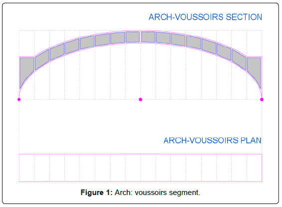
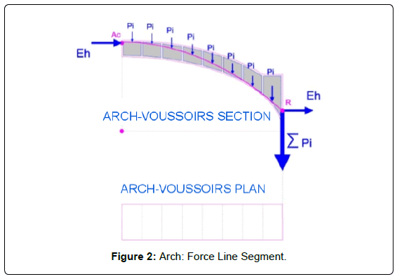
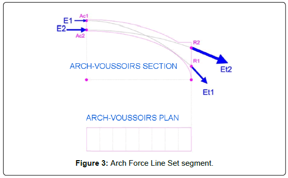
Results are computed by Carybo through suitable analytical expressions from the input typed values. Whenever the force line gets out of the section or the security coefficient decreases below a critical value, the solution shall be discarded and new input values shall be assigned to the variables (either individually or grouped for each step). Obviously, there will be more than one force line to meet those conditions. However, provided energy is not spontaneously wasted, the one with the least horizontal thrust ought to be selected. Carybo divides the semiarch into 100 voussoirs cut by vertical plans. The fact that sections are vertical or radial has no relevance for calculation purposes. As shown in Figure 1 each voussoir is defined by extrados and intrados lines, with a constant width of a hundredth of the arch's length. The thrust line starts in the keystone with the force transmitted by the other semiarch. From this point, the force that each voussoir applies is vectorially summed up (considering each net weight and overload). The sequence of this vectorial set is the thrust line or Force Line, which eventually reaches the support, with horizontal (the one initially applied to the keystone plus punctual horizontal overloads if any) and vertical (own weight, overloads and punctual loads if any) components. The point AC in Figure 2 –Force Line arch- represents the point of application of the force Eh due to the other semi-arch, while point R represents the end of the Force Line at end of the arch. Out of the elements intervening on the Force Line, weights and loads are input data. Thrust Eh due to the other semi-arch and point of application Ac are variables. This way, the modification of the value Eh or the height of Ac leads to the generation of a new Force Line. In any case, this Force Line must be contained within a fringe inside the segment's section, determined by the previously set Geometric Security Coefficient. If the thrust line would get out of the limits, any of the two abovementioned variables could be altered, or even both, until a thrust line meeting the stated conditions is obtained. Out of all the possible Force Lines satisfying the specific requirements that with a lowest horizontal thrust ought to be chosen. In Figure 3 the Force Line undertaking on point Ac1 with associated thrust E1 triggers a reaction on point R1 with magnitude represented by Et1. Similarly, the Force Line undertaking on point Ac2 is associated to force E2, and reaches the end of the arch on point R2 with intensity Et2. For this particular type of arch the upper the location of the point of attack on the keystone of the horizontal force, the higher the intensity of the thrust at the end of the element. The opposite applies to stilted and pointed arches.
Geometric results
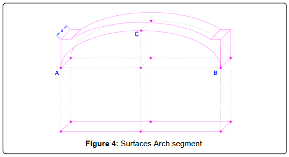
Once the arch intrados and its width are known, the intrados surface can be straightforwardly computed. As can be observed in Figure 4, the length of the curved line ACB times the width d equals the intrados surface, which can also be mathematically obtained by summing up the lower surfaces of voussoirs. The so obtained intrados surface is an “actual magnitude” and serves to quantify the material needed for the construction of the arch [20]. If this surface as realdimension arch is divided by the plant’s projection surface, a one- dimensional value known as Concavity Coefficient is straightforwardly yielded. The so obtained parameter will equal unity and π/2 (and even higher for pointed arches) for a completely flat surface and for a circular arch, respectively. This way, the Concavity Coefficient is linked both to the concavity of the arch as well as to the distance between the keystone and the vertical starting pieces. Values below/above π/2 would therefore represent basket-handled/ pointed or stilted arches, respectively.
Total loads are computed as the sum of all the external loads and those generated by the own net weight. If this value was divided by the arch plan surface, the total (horizontally projected) load per unit area would be obtained. The so computed value is linked to the arch’s net weight and is also a key parameter for builders to quantify material costs for the whole arch, including the sinus filling.
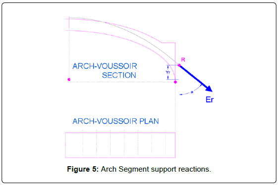
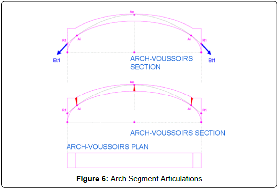
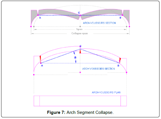
The Force Line ends in the arch extreme on point R (Figure 5) at height Yr as referred to the arch starting point, with total intensity Er and inclination angle a. The arch will be supported by an element such as a wall or a column. This will be the result used in the support analysis, keeping in mind that it should meet this action for that particular value and for that specific point of application. The resultant Era has two components. A vertical one, as the net weight of the arch plus vertical overloads, and a horizontal one, which depends on equilibrium conditions. The lower the arch’s horizontal component is, the more stability it will show. Moreover, the lesser the horizontal component is, the lower the point of application R will be located. Prior to collapse, the articulation points are those for which the force line approaches the section limits (Figure 6). Articulations are the points at which the arch breaks to turn into a mechanism. When arch supports suffer small displacements, cracks coincident with the opposite side articulations will appear. Intrados articulations will therefore provoke cracks in the extrados and vice versa. Three articulations are at least needed for collapse to take place. If a shift in the support location was assumed, the arch would be divided in four elements linked by the articulations, which also operate as hinges. Whenever there is enough space for the arch elements to fall, collapse will take place (Figure 7). At this moment the three articulations would be horizontally aligned. Collapse span is the arch span plus 2xAC (1-cos(a)), meaning twice the distance between articulations (AC) multiplied by one minus the cosine of the angle formed by the line joining two consecutive articulations and the horizontal line. This is the theoretical instant at which collapse is expected to occur, but it actually takes place previously, when corner articulation points break. However, collapse span values are useful to compute how close an arch stands from its critical state. For instance, the closer the distance between articulations, the lower the collapse span; whereas the higher such distance is, the higher the shifts between supports required reaching collapse will be. The Geometric Safety Coefficient (GSC) is a one-dimensional value indicating thrust location relative to the limit for each voussoir. A minimum value of 1.1 was set, which stands for 90% of the section. This way, points with GSF 1.1 correspond to articulation points. The higher the GSC, the closer to the section centre the Force Line will be. GSC values indicate the location of the Force Lines within the arch. When the strength traversing each voussoir is known, its stress value can be obtained by simply dividing such strength by the voussoir section. Such values are usually far below the admissible material stress and therefore they are not relevant for arch´s stability tests.
Set of parallel-sided segments: Carybo was used to analyse three square-based vaults (barrel, groin and dominical type), each showing a different geometrical section. Plane dimensions and loads were set as constant values. Each of these three types of vaults shows a different structural behaviour.
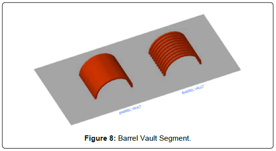
Barrel vault: Consists of a series of arches located one next to each other. From a structural point of view, the mere analysis of a single vault segment would allow achieve the information required. The analysis of a barrel vault would need to have it sectioned in a series of vertical planes parallel to each other at a given constant distance. One single segment (an arch) should be analyzed to further export output data to the complete vault (Figure 8).
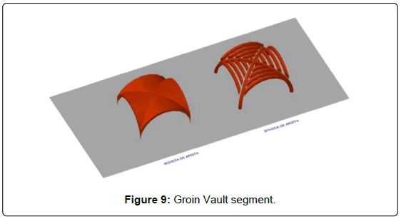
Groin vault: A groin vault is defined by the intersection of two barrel vaults. It should be divided into a set of arches in order to undergo an appropriate analysis. Firstly, two arches corresponding to the diagonals between opposite corners, crossing at the keystone, should be considered. Secondly, each of the four barrel vaults will be divided in arches. This vault’s arches span will be lower as they reach the keystone, and they are not supported by walls but by the diagonal arches. Every arch, or portion of arch, should be analysed independently according to its specific geometry and load. Diagonal arches will be analyzed keeping in mind that they are supporting the corresponding barrel vault’s arches, therefore receiving every transmitted stress (Figure 9).
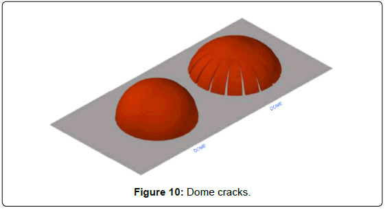
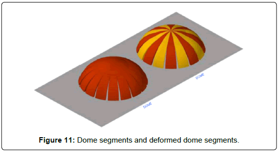
Converging-sided segment: Jack Heyman pointed out the most common of dome cracking processes, which is indeed easy to observe: just take the already pressed half of an orange, put it on a table and push it until cracks start to appear. As shown in Figure 10, radial cracks of a certain length (the top not being reached) will appear. When dividing a dome, the obtained segments will not show parallel sides as in barrel vaults. Instead, a revolution surface will be generated, and therefore wedge shaped segments (narrower at keystone and wider at base) will appear when decomposed. The way the dome cracks gives a hint on which sections are independent in extreme situations, as applied for the groin vaults. Structurally, the dome is divided into independent elements that work separately. Cracks set the limits among segments. Of course, only segregation cracks are referred to, and not articulation ones. Such cracks can be noticed both at the intrados and the extrados. No stress takes place on them, not even in a single point, as it happens in articulation cracks. If Heyman's deformed dome is divided in segments, matching every crack with its corresponding element would yield the situation of the Figure 11. The difference among barrel vault segments and revolution dome segments lies in the position of the outer sides, which remain parallel or converge to the highest point (i.e. keystone) if vault or dome segments are accounted for.
An isolated dome segment is self-stable since it is balanced by its opposite half segment. However, dome segments, corresponding to dome semi-sections, are not balanced by collateral ones. This reasoning is self-evident when considering a dome with a central oculus, where no contact between opposing segments exists. If a semi-section is accounted for, the supports ought to be substituted by the forces they are applying if equilibrium needs to be maintained. In the case of the dome, the force is applied by the opponent semi-arch. However, in the case of vaults, the forces involved are those applied by the collateral semi-sections (Figure 12).
Let us finally give the geometrical definitions of some relevant elements:
a) Dome: revolution surface generated by the spin of a curve around a vertical axis located on the highest part of the curve. This way, a sphere might be regarded as a dome whose generating curve is a circumference with an axis situated on the circumference's upper quadrant [21].
b) Fan vaults: revolution surface generated by the spin of a curve around a vertical axis, situated on the lower part of the curve. Dome and fan vault sections are therefore inverted as compared to each other [22].
c) Toroid vaults: revolution surface generated by the spin of a curve around a vertical axis located at a certain distance from the curve.
d) Spiral stairway: It is strictly a helicoid. This surface cannot be dissembled in coplanar segments but in non-coplanar segments, and therefore cannot generate a coplanar Force Line. In this case, not only the gravitational force and the thrust are acting, but also a rare one, the centrifugal force, which will compel the gravitational forces to travel a path that doesn't match the steepest line.
Conclusions
The groin vault is the lightest (1.514 N/m2) and that with the lowest Concavity Factor (1.14), while the dominical vault stands as the heaviest (2.244 N/m2) and shows the highest Concavity Factor (2.07). On another note, the barrel type is only supported by its sides (4.610 N horizontal thrust applied on each one), the groin vault on its four corners (horizontal thrust 3.102 N, diagonally directed) and the dominical type on its four sides (1.524 N horizontal thrust on each). Despite stress values on the three vault types are low, a couple of points ought to be accounted for. The maximum stress on the groin vault is 0.03 N/mm2 with a significant increase up to 0.34 N/mm2 as the edges are approached. The maximum radial stress –transmitted to the supporting elements- on the dominical vault is 0.03 N/mm2, although a parallel-to-the-supports ring stress appears (whose intensity depends on proximity to vertical position as related to the supports) ranging up to 0.17 N/mm2, quite higher than the radial stress. Maximum work stress is not the defining value in order to guarantee stability for this element. The thrust tilt of these three types of vault is visibly different. The most horizontal thrust (48° subtended angle with respect to the horizontal plane) was observed for the groin vault, while the steepest one was seen to correspond to the dominical vault (73° inclination). Due to support displacement, the distance between joints is somehow linked to the remaining time until collapse. The closer they are, the faster the structure will collapse. In this sense the safest vault is the barrel type, provided its joints are separated 38% of total span. On the other hand, the dominical vault was regarded as the least safe, as the joints are separated 20% of total span.
Discussion
The oil crisis favoured the consumption of materials such as charcoal and the recovery of old technologies like wind mills in order to take advantage of other energy sources such as the Eolic. Likewise, vaulted constructions may be somehow recovered in the future for unexpected reasons.
The use of vaults is currently mainly justified by ornamental aims, intentionally eluding its structural character. To avoid this drawback as compared to concrete structures in the market, a standard with similar characteristics to that available for materials like concrete and steel should be available. The fact vaulted structures are not accounted for by building regulations –neither new nor restoration projectsclearly relegates such constructive element to the background. It would therefore be advisable to issue specific minimum standards that would allow their use offering a minimum guarantee both for constructors and users, like for instance the implementation of technical codes similar to the existing European “eurocodes” for concrete, steel, wood, etc.
Acknowledgements
The authors wish to express their gratitude to the Regional Ministry of Health and Dependence of the Regional Government in Extremadura, as well as to the National Institute for Health Management, for the vast information provided during the course of the present work, which was supported by Project GR 10099 from the Regional Government of Extremadura and the European FEDER funds.
References
- Cassinello F (1969)Vaults and domes frombrickpatronageJuan fromthehind of CSIC. Madrid.
- Auguste C(1980) History of theArchitecture Buenos Aires, Víctor Leru Editorial.
- Leal JS (2000) Bovedas de ladrillo que se ejecuta sin cimbra, Madrid, Imprenta del Memorial de Ingenieros.
- Paredes GuillenVicente (2004)Treatyfromyouvaultswithoutformwork. counselingfrompromotion, Badajoz, Spain.
- Lobez GY (1915) Manual from civil buildingbyFlorencio.PrintingtheMinerva Extremadura, Badajoz.
- Vicente TT (1727)Treatyfromthe Montea y Politefromstonework. Paris-Valencia Bookstores, Valencia.
- Blanco LM (1993) YouVaultspartitioned :Secondpart, TheArchitecturePolite and otherwritings ,collectionscatteredtexts, Facsimileedition, OfficialCollege of Architects of Madrid.
- Barrozzi De Vinola, IaCome (1996)Thetwo rules praticaperspective. Facsimileeditiontranslated and commentedby Salvador Muñoz. Real Academy of Extremadura of theLetters.
- Gurrea FY (1841) Observationsonthepractice of art of building . Valencia, PrintingFacsimileCabrerizo , Editorial Maxtor . Valladolid.
- Sanz-CalcedoGJ, ForteaM, Reyes MA (2012 )ComparativeanalysisonenvironmentalsustainabilityBetweenmasonryvaults and concrete structures . Magazine fromEngineeringConstruction 27: 5-22.
- Jacques H (1966)The Stone Skeleton. International Journal of Solids and Structures 2: 249.
- Santiago H ( 2006) Diseriostructural in thework of Gaudi . Opinionarchitecturalscience 49: 324-339.
- Baker JF, Horne MR, HeymanJ (1956)The steel skeleton. Plastic behaviour and design. Cambridge UniversityPress 2.
- Moon MF (2008) TheChurch of theMagdalene of Olivenza ,Portuguese Gothic model . Caja de Badajoz.
- Jacques H (1999)The Science of Structural Engineering. Imperial College Press, London.
- Gvozdev AA (1960)The determination of the value of collapse load for statically indeterminate systems undergoing plastic deformation. International Journal of Mechanical Sciences 1: 322-35.
- FernandezHS(2001)Mechanics of masonryvaults: Theequilibriumapproach 47-69.
- Zabaglia,Nicola (2005)Ponti e Castelli. Instituto Juan de Herrera, School of Architecture, PolytechnicUniversityfrom Madrid
- Luna MF, Bernal VL (1998)BovedasExtremenasOfficial College of Architects of Extremadura.
- Hernán Ruiz Ii (1998)Book of Architecture, facsimileeditionWithJimenezintroductorystudiesby Martin et al., Sevilla, Foundation Sevillana Electricity.
- Guastavino R (1893)Essay on the theory and history of cohesive construction. Applied especially to the timbrel vault, Boston, Ticknor and Company.
- Viollet-Le-Duc EE (1996)The medieval building , Madrid, Institute John, Herrera
Relevant Topics
- Architect
- Architectural Drawing
- Architectural Engineering
- Building design
- Building Information Modeling (BIM)
- Concrete
- Construction
- Construction Engineering
- Construction Estimating Software
- Engineering Drawing
- Fabric Formwork
- Interior Design
- Interior Designing
- Landscape Architecture
- Smart Buildings
- Sociology of Architecture
- Structural Analysis
- Sustainable Design
- Urban Design
- Urban Planner
Recommended Journals
Article Tools
Article Usage
- Total views: 18549
- [From(publication date):
October-2015 - Apr 21, 2025] - Breakdown by view type
- HTML page views : 13646
- PDF downloads : 4903

