Design and Control of a Self-Balancing Autonomous Underwater Vehicle with Vision and Detection Capabilities
Received: 08-Dec-2017 / Accepted Date: 04-Jan-2018 / Published Date: 07-Jan-2018 DOI: 10.4172/2155-9910.1000245
Abstract
In this paper, the authors discuss the design and control of an autonomous underwater vehicle with vision and detection capabilities. The tasks involved the design of various mechanical parts, particularly two rotating thrusters and a mass shifter to control the device movement. Sensor boards were also embedded to share information with a Mini-PC board and thus, to assure proper operation. Control-based algorithms were developed to control the vehicle operation and assure proper responses to external commands and/or surrounding conditions.
Keywords: AUV; PID; Fuzzy Logic Controller
Introduction
Nowadays, small autonomous underwater vehicles (AUVs) are strongly preferred for the remote exploration of unknown and unstructured environments. Such devices allow the exploration and monitoring of underwater environments where a long term underwater presence is required to cover a large area [1-3]. Furthermore, reducing size, energy consumption, and cost, while embedding various mechanical/electrical parts, is some of the challenges AUV designers are facing.
The main purpose of this work, we designed an autonomous underwater AUV prototype with vision and detection capabilities. The tasks involved the design of various mechanical parts, particularly two rotating thrusters and an interior mass shifter to control the device movement. Sensor boards were also embedded to share information with a mini-PC board and thus, to assure proper AUV operation. Control-based algorithms were developed to control the AUV operation and assure proper responses to external commands and/or surrounding conditions. Also, two cameras were used to collect information about the surrounding environment and an image processing technique implemented to treat the images sent by the cameras and then, to detect potential obstacles.
To do so, we started with the AUV body by selecting a shape and subdividing it into blocks in order to locate all embedded mechanical and electrical components required for proper operation under real environmental conditions; the objective being to achieve a good tradeoff between size and weight.
Next, we included the mass shifter to control the AUV movement and assure its stability. We also designed a sensor board, a power board, an access board, and a motor driver board as well as a mini-PC to manage the data exchange with the different mechanical and electronic parts like the IMU, pressure, and compass sensors. Note that a particular effort has been made to significantly reduce the electronic connections and avoid energy waste.
After receiving predefined-user commands regarding the desired arrival point to reach at a certain depth and with a certain speed, the AUV was able to perform the task by efficiently changing its driving motors’ speed and servomotors’ angle. This played an important role in preserving the energy resources of the AUV, thus increasing its autonomy. Finally, after more than 800 hours of testing under various operating conditions including both pool and ocean environments, the designed AUV successfully responded to all commands and efficiently detected fixed obstacles by taking appropriate decisions.
System Description
Body design
To safely navigate, an autonomous vehicle should be able to accurately detect obstacles, make quick and appropriate decisions and select the suitable route to circumvent them. To this aim, we designed a research prototype which main characteristics are the simultaneous use of two thrusters located in a specific angles so both vertical and horizontal forces needed are provided simultaneously. Furthermore, the change of angle can be made possible by the instant movement of an engine stopper, which consumes much less energy than the constant movement of a thruster (Figure 1).
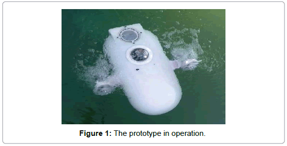
Figure 1: The prototype in operation.
In designing this AUV, we also included a mass shifter, first because of the thruster movement and second to make the maneuver possible in the direction of the pitch. The whole set can have two movement modes. In the first mode, the body should, by the help of the mass shifter, have a constant horizontal movement and its movement towards vertical and horizontal directions should be performed through a change in the thruster angle. In the second mode, the thrusters should be kept fixed in a horizontal direction and the vertical movement should be made possible through a change in the body angle in the pitch direction. The first mode is used wherever there is little room of maneuver or to pass obstacles while the second mode is used to preserve and store the source of energy and make changes in great depths.
Main processor
All AUV processes including camera/sensor data, contouring obstacles, controlling motor operation, etc., should be managed via a main processing board. In this work, we used the mini pc board Giada i200-BG000, Celeron [4]. All ports of this board have been used. The serial port has been dedicated to the rotating body while the two cameras, the sensor board and the transceiver module have been connected to the USB ports. Figure 2 shows the block diagram of the Main Processor with the interconnected modules of the AUV. In fact, because the Magnetometer sensor is highly sensitive to electromagnetic noise and the earth magnetic field intensity quite weak under water, we had to use a separate digital compass sensor to increase accuracy. The selected compass sensor is the HMC6343, a fully integrated highend electronic compass module that can compute and give an accurate heading direction within a couple of degrees. It combines 3-axis magneto-resistive sensor and 3-axis MEMS accelerometer and can compute a heading direction every 200 ms [5].
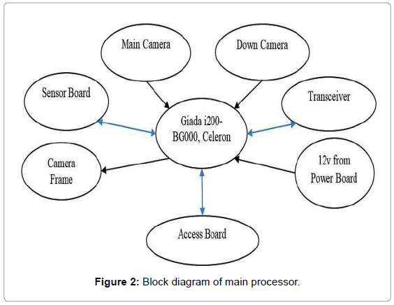
Figure 2: Block diagram of main processor.
Because there is a linear relation between water pressure and water depth, we used a new generation of high resolution pressure sensors with I2C interface, i.e., the MS5803-14BA pressure sensor [6] to measure the device depth.
Noiseless Mode Control
The noiseless mode represents the situation in which the vehicle is in a smooth state and moves in an environment free of noise and obstacles (Figure 3). In this mode, it is enough for the servo to put DC engines along the movement track of the vehicle (i.e. with a servo of zero angles) (Figure 4).
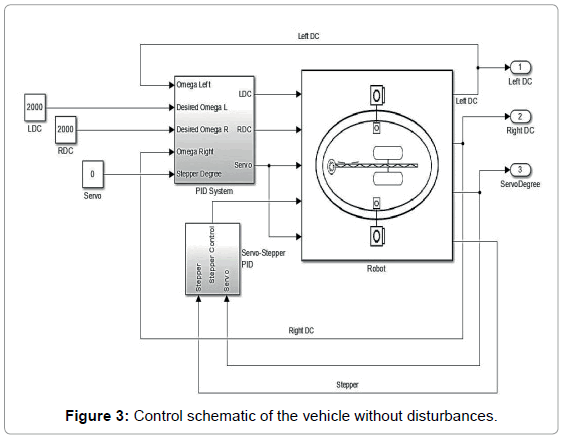
Figure 3: Control schematic of the vehicle without disturbances.
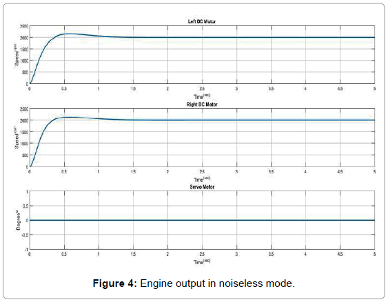
Figure 4: Engine output in noiseless mode.
Sensors
In this work, we used several different sensors. The common factors in selecting these sensors are their reasonable price, very small size, and good performance. They should also exhibit high sensitivity and resistance against heat, as well as low current consumption and be able to work with I2C communication protocol [7,8].
Thus, a MPU-9250 Inertial Measurement Unit (IMU) sensor has been used [9]. It is composed of three sensors, i.e., an acceleration counter to measure the acceleration of the device, its balance and its deviation, a gyroscope to measure the circulation rate of the device and finally, a manometer to determine the position of the device relatively to the North Pole. A compass sensor was also included to determine the heading point.
Navigation
The first and most basic control goal of this AUV is to move in a certain direction or a particular track. Then, it measures the AUV deviation from a predefined track and forces it to move in the desired direction. The mentioned thrust is provided to DC engines by a closed loop proportional controller with servo motor of zero angles. Thus, the reference controller input is the defined track for the compass sensor. So, the difference between the current angle read by the sensor and the track defined for the sensor is calculated and sent to the proportional controller. If the angle deviation with the reference angle is positive, the left engine is turned on and tries to compensate the angle difference with the track. Similarly, if the angle deviation is negative, the right engine is turned on so that the AUV gets back to the desired track (Figures 5 and 6). It should also be noted that, by this strategy, the AUV is controlled in Yaw degrees of freedom.
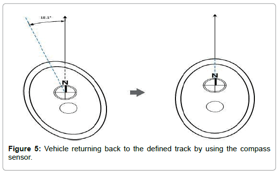
Figure 5: Vehicle returning back to the defined track by using the compass sensor.
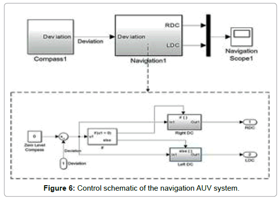
Figure 6: Control schematic of the navigation AUV system.
It seen in Figure 7, as a result of a sudden 18.1° deviation, a command is quickly sent to create a force through the left engine (maximum velocity of 133 rpm), letting the AUV to return to its main track.
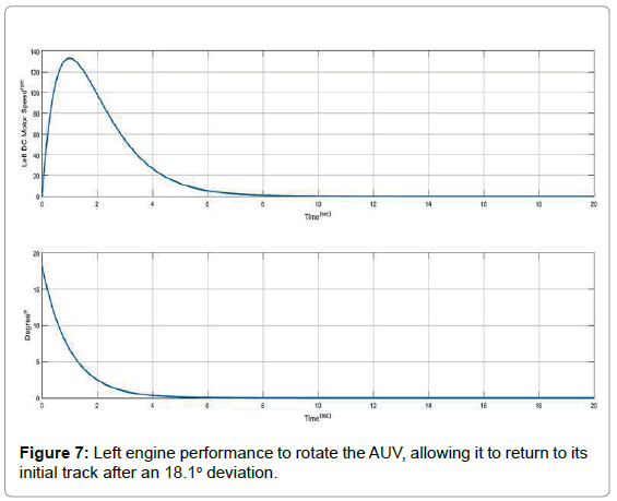
Figure 7: Left engine performance to rotate the AUV, allowing it to return to its initial track after an 18.1o deviation.
AUV Balancing
The balancing control is similar to navigation. First the vertical servos of both sides take the 90° position (initial position). Then, the IMU sensor sends data to the processor about the Roll angle difference to determine the performance of the DC motors and the AUV to reach the balance position. Note that the velocity is progressively reduced when approaching the balance. If the AUV is rolled to its left side, the left DC motor starts to rotate and create a force in the opposite direction so that the AUV is dragged into its balanced position (Figures 8 and 9).
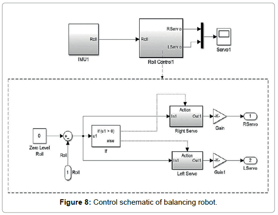
Figure 8: Control schematic of balancing robot.
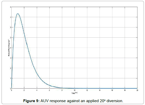
Figure 9: AUV response against an applied 20o diversion.
Fuzzy Logic Controller and Vision System
Controller
At this stage, two more features were added to make it relatively autonomous, i.e., a Fuzzy-based control decision system and a central control signal system. In the control decision stage, a phase system should take the best decision for the next move after diagnosing an obstacle ahead. Then the decision is transmitted to the central unit, which sends the required commands to the AUV engines for proper movement.
Fuzzy systems are knowledge- or rule-based systems. The heart of a fuzzy system is composed of fuzzy IF-THEN rules. A fuzzy if-then rule is an if-then term if its words are determined by continuous membership functions [10-14]. A fuzzy controller is composed of four main parts: Fuzzifier, rules base, decision making part, and Defuzzifier (Figure 10). Note that before and after the fuzzy controller, preprocessor-and postprocessor are usually included.
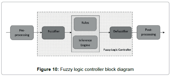
Figure 10: Fuzzy logic controller block diagram
Vision system
To apply fuzzy logic to obstacle detection, each picture is first subdivided into three horizontal/vertical bands and a score assigned to each of the six bands. This number is equal to the ratio of white pixels to the total number of pixels in the section. To prevent noise error in image processing, we set a threshold: if this ratio is less than 2% for the whole image, this later is assumed free of obstacles. A sample scoring is illustrated in Figure 11.
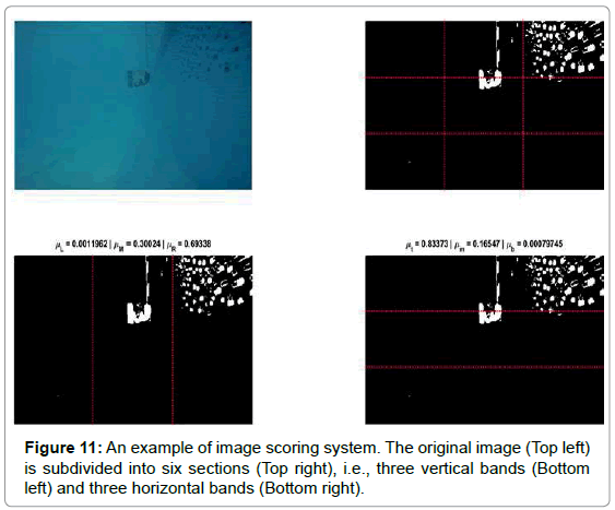
Figure 11: An example of image scoring system. The original image (Top left) is subdivided into six sections (Top right), i.e., three vertical bands (Bottom left) and three horizontal bands (Bottom right).
Then, to prepare the fuzzy system inputs, let us state the band scores as μL (left vertical band), μM (middle vertical band), μR (right vertical band), μt (top horizontal band), μm (middle horizontal band), and μb (bottom horizontal band). Then, Table 1 summarizes the fuzzy controller inputs, knowing that each of the above scores is reduced from the middle part score.
| µL-µM | Left/Right |
| µR-µM | FLC Inputs |
| µt-µm | Up/Down |
| µb-µm | FLC Inputs |
Table 1: Models fuzzy decision system.
The fuzzy system decision is based on the score each section got compared with its corresponding middle band. Let us consider first the vertical bands and assume, for instance, that the term μL-μM is negative; the vertical middle part will obtain both a higher score in detecting an obstacle and a higher share than the left band in terms of location. Therefore, the left vertical band is a better choice for the AUV’s next movement. At the same time, the term μR-μM is calculated and by comparing it to the previous one, the fuzzy system will make its decision regarding the updated Yaw direction of the AUV. The decision output will then determine the differential velocity between the left and right engines. The number provided by the fuzzy system will be reduced from the average velocity of the left DC engine and added to the right DC engine. The fuzzy rules for this system are shown in Table 2 witch shown with PB: Positive Big, PS: Positive Small, NS: Negative Small and NB: Negative Big.
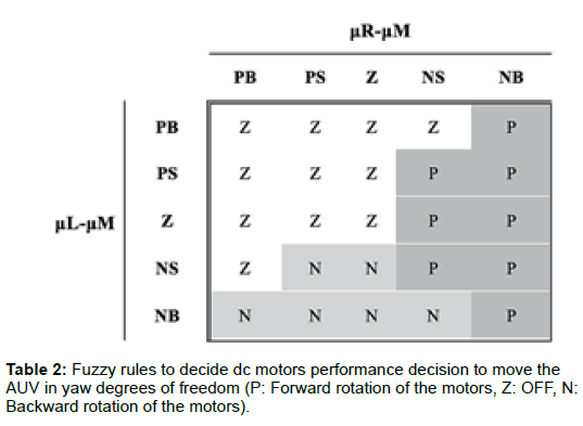
Table 2: Fuzzy rules to decide dc motors performance decision to move the AUV in yaw degrees of freedom (P: Forward rotation of the motors, Z: OFF, N: Backward rotation of the motors).
The above decision Table 2 was set to favor direct tracks. In fact, if the vertical side bands are not significantly different from the middle band in terms of scoring, the direct track is the AUV’s next decision to move. Accordingly, sudden and large movements in a given direction are avoided and wasting control commands reduced. The input and output membership functions of the fuzzy decision system are shown in Figures 12 and 13, respectively.
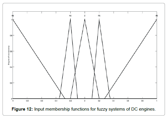
Figure 12: Input membership functions for fuzzy systems of DC engines.
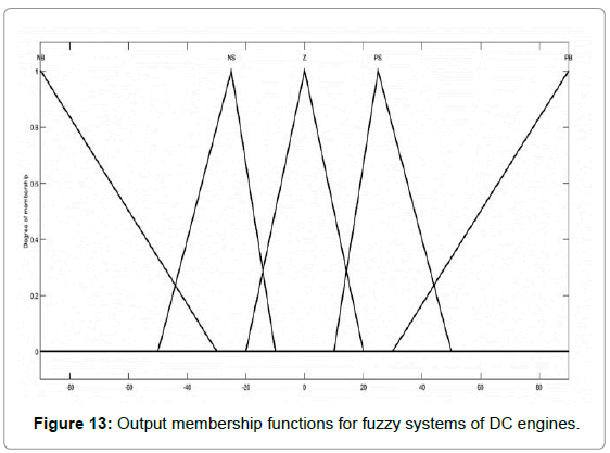
Figure 13: Output membership functions for fuzzy systems of DC engines.
Like the vertical fuzzy system, the rules of the fuzzy controller were designed to orientate the AUV. Figure 14 shows the system input membership functions. It should be mentioned that multiplying the scoring with a fixed number (90) gives a range between -90 and +90, and then, output angles between -60° and 60°. The output membership functions are shown in Figure 15. Note that the fuzzy system output for servomotors is a Singleton.
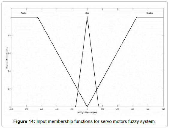
Figure 14: Input membership functions for servo motors fuzzy system.
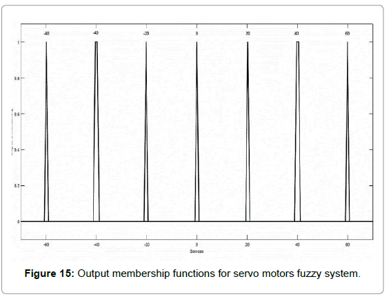
Figure 15: Output membership functions for servo motors fuzzy system.
Note that the above membership functions were set after performing numerous tests and analyzing their performance on different images.
Similarly, there is another fuzzy controller which considers the difference between horizontal upper and lower sections and the middle one; the logic function is similar to FLC in DC engines. After performing the fuzzy operation, the fuzzy system output represents the angle in which the servomotors should be positioned (Table 3).
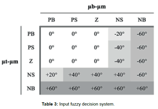
Table 3: Input fuzzy decision system.
PID Control Algorithm
As mentioned in the fuzzy section, the fuzzy system outputs are sent to the PID controllers as reference inputs. For example, after the fuzzy decision to increase the velocity of the left engine up to 2450 rpm, a force is applied to the AUV at its left and the AUV would rotate toward its right side. In fact, encoders installed along the DC engines read the current engine velocity and the obtained value is compared with the reference velocity. The reference velocity error is then presented to the PID controller, providing a control command to the DC motor driver. Figure 16 shows the PID loop algorithm.
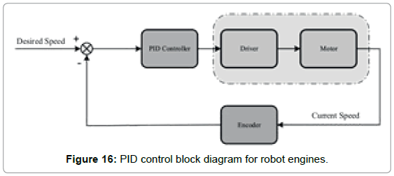
Figure 16: PID control block diagram for robot engines.
In order to keep the AUV balance, the stepper motor and the servo motor are placed in the same loop such that the desired angle corresponding to the stepper motor mirrors the reference angle for the servo motor. Figure 17 shows the block diagram of this process while the overall control schematic is described in Figures 18 and 19.
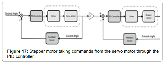
Figure 17: Stepper motor taking commands from the servo motor through the PID controller.

Figure 18: Barrier escape control strategy.
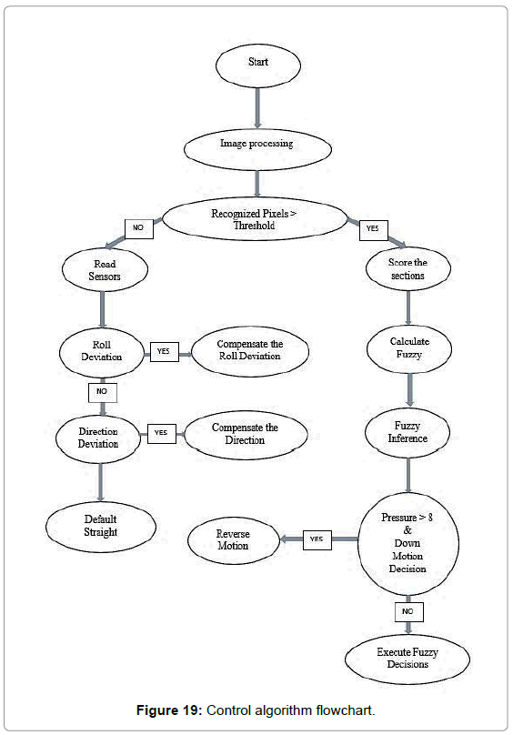
Figure 19: Control algorithm flowchart.
Experimental Test
The experimental test was to place an obstacle in front of the AUV path, as shown in Figure 20. Let the normal velocity of both the left and right engines be 2000 rpm. To skirt the obstacle, the AUV decided, according to the scores got from the controller, to roll into the left and go down with a gentle angle. To this aim, the left engine velocity was reduced and the difference added to the right engine velocity, leading to the following quantities:
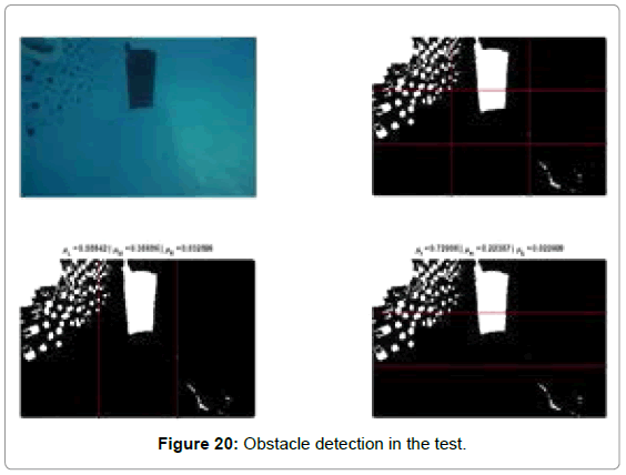
Figure 20: Obstacle detection in the test.
• Left DC engine command velocity: 2000 - (-523) = 2523 rpm
• Right DC engine command velocity: 2000 + (-523) = 1477 rpm
Thus, because the moment created in the left side of the AUV is higher than the right side, the AUV bended to the right side. As for the test, the entire sequence loop was controlled by the PID algorithm.
Note that after scoring, an optimal angle was determined and sent as command to the servomotors. In this case, a -20o correction was found to be adequate to balance the AUV and therefore, the angle of the stepper motor, following the opposite of the servo angle, was set to +20o. Thus, the AUV’s top goes down and right to avoid the obstacle. The above process is described in Figures 21 and 22.
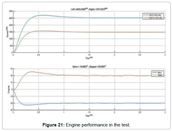
Figure 21: Engine performance in the test.
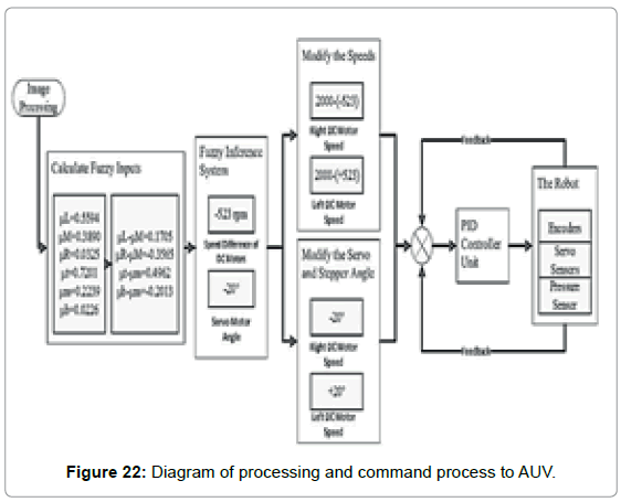
Figure 22: Diagram of processing and command process to AUV.
Conclusion
In this paper, we designed a lightweight and autonomous underwater vehicle with vision capabilities allowing detecting and contouring obstacles; It is indeed an exciting challenge to build a small and light submarine AUV, while making tradeoffs between performance and minimum available space as well as energy consumption. In fact, due to the ever-increasing in equipment complexity and performance, designers of AUVs are facing the issues of limited size and energy consumption.
By using a pair of thrusters capable to rotate 360o on their axis and implementing a mass shifter with a control loop inside the vehicle, this later can efficiently adapt its depth and direction with minimal energy consumption. A prototype was fabricated and successfully tested in real operating conditions (in both pool and ocean). It includes the design and embedding of accurate custom multi-purpose sensors for multitask operation as well as an enhanced coordinated system between a high-speed processor and accustomed electrical/mechanical parts of the vehicle, to allow automatic controlling its movements.
Furthermore, an efficient tracking system was implemented to automatically detect and bypass obstacles. Then, fuzzy-based controllers were coupled to the main AUV processor system to provide the best commands to safely get around obstacles with minimum energy consumption. The fabricated prototype was able to work for a period of three hours with object tracking options and five hours in a safe environment, at a speed of 0.6 m/s at a depth of 8m.
References
- Han KM, Choi TH (2011) Shape context based object recognition and tracking in underwater environment, IEEE Int. Geoscience and Remote Sensing Symposium.
- Choi HT (2010) New project and new underwater robot for new missions. Int Conf on Advanced Mechatronics, Osaka, Japan.
- Choi HT, Lee PM (2004) Development of a system architecture for an advanced autonomous underwater vehicle, ORCA. Int. Conf. on Communications, Circuits and Systems, Bangkok, Thailand.
- Petrich J, Neu WL, Stilwell DJ (2007) Identification of a simplified AUV pitch axis model for control design: Theory and experiments, IEEE Oceans Conf., Vancouver 1-7.
- Three-axis Compass with Algorithms HMC6343, Honeywell’s Magnetic Sensors, 2014.
- i200, 4th Gen. Intel® CoreTM i3/i5/i7 Processor Intel® HD Graphics 4400, Intel, 2015.
- Petrich J, Stilwell DJ (2010) Model simplification for AUV pitch-axis control design, Ocean Engineering 37: 638-651.
- MPU-9250 Product Specification, Document Number: PS-MPU-9250A-01, InvenSense Inc, 2014.
- MS5803-14BA Miniature 14 bar Module, Measurement Specialties Inc., 2012.
- Kanakakis, Valavanis KP, Tsourveloudis NC (2004) Fuzzy-logic based navigation of underwater vehicles. Journal of Intelligent and Robotic Systems 40: 45-88.
- Tamir DE, Rishe ND, Kandel A (2015) Fifty Years of Fuzzy Logic and its Applications, Springer.
- Zadeh LA (1996) Fuzzy logic computing with words. IEEE Trans Fuzzy Systems 4: 103-111.
- Banks W, Hayward G (2002) Fuzzy Logic in Embedded Microcomputers and Control Systems, Byte Craft Ltd.
- Metcalfe G, Olivetti N, Gabbay DM (2008) Proof Theory for Fuzzy Logics. Springer.
Citation: Jebelli A, Yagoub MCE, Dhillon BS (2018) Design and Control of a Self- Balancing Autonomous Underwater Vehicle with Vision and Detection Capabilities. J Marine Sci Res Dev 8: 245. DOI: 10.4172/2155-9910.1000245
Copyright: © 2018 Jebelli A, et al. This is an open-access article distributed under the terms of the Creative Commons Attribution License, which permits unrestricted use, distribution, and reproduction in any medium, provided the original author and source are credited.
Share This Article
Recommended Journals
Open Access Journals
Article Tools
Article Usage
- Total views: 6612
- [From(publication date): 0-2018 - Dec 19, 2024]
- Breakdown by view type
- HTML page views: 5720
- PDF downloads: 892