Research Article Open Access
Comparative Study of Intraorganelle Nanoporation among Osteoblast and Bone Cancer Cell in 3D Advanced Microchip
| S Sarkar* | |
| Department of Electronics and communication Engineering, Sikkim Manipal Institute of Technology (SMIT), Gangtok, Sikkim, India | |
| Corresponding Author : | Swarup Sarkar Department of Electronics and communication Engineering Sikkim Manipal Institute of Technology (SMIT) Gangtok, Sikkim, India Tel: +919002449818 E-mail: swarupsarkar957@yahoo.com |
| Received December 21, 2015; Accepted January 19, 2016; Published January 26, 2016 | |
| Citation: Sarkar S (2016) Comparative Study of Intraorganelle Nanoporation among Osteoblast and Bone Cancer Cell in 3D Advanced Microchip. Biochem Physiol 5:196. doi: 10.4172/2168-9652.1000196 | |
| Copyright: © 2016 Sarkar S. This is an open-access article distributed under the terms of the Creative Commons Attribution License, which permits unrestricted use, distribution, and reproduction in any medium, provided the original author and source are credited. | |
| Related article at Pubmed, Scholar Google | |
Visit for more related articles at Biochemistry & Physiology: Open Access
Abstract
In this research, the comparison study of intraorganelle nanoporation and ion uptake of osteoblast and tumor cells has been studied under the influences of specific programmable of picopulse generator and specific microchip. By using the MATLAB and COMSOL, the difference in responses of the normal and tumor cells for a given input picopulse are elucidated. A comparison of the induced intraorganelle potential, current, pressure, surface tension, pore density and ion uptake of the tumor cells against normal cells have been studied and it is shown that nearly 40% increase of nanoporation is observed in the tumor cell compared to the normal cell for a dedicated picopulse in 3D advanced micro chip and it is control by external user and the threshold pulse duration is 10-12 and 10-15 for normal cell and cancer cell respectively.
| Keywords |
| Picoseconds pulsed electric field (psPEF); Hybrid microchip; Osteoblast cell; Intraorganelle nanoporation; Cancer cell |
| Introduction |
| Nanoporation and bio-electric effect on cancer cells exposed to a specific pulse are the advanced applications in medical treatments, especially for cancer treatment [1]. The effectiveness of the cancer treatment depends on specification of electric pulse and the conductivities and relative permittivities of the cell. But till now the information regarding the pore formation and ion uptake on intraorganelle for cancer cell are limited. Cancer is a specific type of disease, where cells are grown non-uniformly and divide without respect to normal limits. It also destroys the adjacent cell and spreads to the other location of the body [1]. A number of techniques are implemented to destroy the cancer cell but all these processes have number of side effects and they are most costly. The upcoming treatment is the use of electrical pulse-mediated chemotherapy using the electroporation concept, known as Electrochemotherapy (ECT) [2]. Exposing tumor cells to electric field causes buildup of charges in the cell membrane and consequently a change in the transmembrane potential of the cell [3]. For low electric fields, this causes voltage gating of the protein channels in the cell membrane. With increasing electric field, induced transmembrane voltages on the order of 1V form electropores on tumour cell membranes. It is believed that the pore formation generates large openings in membrane accounting for transfer of large molecules across the tumor cell membrane. The most important parameters for effective electroporation are the electrical field strength and length of time the field is applied [4]. A large variety of other parameters can influence the efficacy of electroporation, such as the shape of the electrical pulse, polarity, size of target cells, and thermal conditions during and after the pulse, as well as other cellular and environmental factors. The uptake of molecules depends also on molecular size, applied electrical field and other physicochemical properties [5]. Among them the charges accumulate at the plasma membrane of a biological cell when a voltage pulse is applied to it, and the induced potential across the membrane is increased [6]. Electric field strengths of suitable magnitudes and durations cause molecules and molecular organizations such as biological cell membranes to undergo structural rearrangements. So it is necessary to study the electric field distribution of different electrode configurations [7]. Whether the applied input is ac or dc, when the applied electric field is of such a magnitude to induce a membrane voltage of about 0.5-1 V, the membrane becomes permeable to macro and xeno molecules to which it would be impermeable [8]. The application of electric pulse on cancer cell explores the possibilities of introduced the specific drugs through the membrane but due to the rigidness of intraorganelle layer of cancer cell, the drugs cannot successfully penetrate the complete cell. In this respect the nanopulse is more effected [9]. |
| In this context, a nanopulse generator with intensities between 20 and 150 kV/cm has been developed that provides a new important investigation field. Different works have been reported about the effects on animal cells of these kinds of pulses, commonly named as nanosecond pulsed electric fields (nsPEF). More precisely, it has been shown that the gene electrotransfection efficiency can be improved by nsPEF exposure, also called as nanoporation, and that disturbances on the cell membrane could be sufficient to render it permeable to small molecules, such as propidium iodide [10] . Beyond their potential effects on the cell membrane, these nsPEF show a great interest because they also offer the possibility to disturb the intra cellular structures and functions [11]. But due to the rigid and non-uniform intra cellular structure of osteoblast cell, it was the challenge to the scientist. In this context we are able to overcome the limitation by 3D multilayer micro biochip under the influences of short duration pico electric field [12]. Now we focus on the nanoporation of bone cancer cell and in this research paper the comparative study on intraorganelle nanoporation among the normal osteoblast cell and cancer cell placed in a hybrid microchip under the influences of controllable pico pulse generator has been thoroughly discussed and remarkable observations are found, which could provide more light to the bone cancer treatment. In the first part of this paper, the microchip design and dimension is discussed whereas in remaining part comparative study among the cancer cell and normal osteoblast cell is explained. |
| Materials and Methods |
| Design consideration of the microchip |
| To determine the layout of the electrodes, it is necessary to estimate the forces acting on the particle of interest, cells, at different locations within the device. At each point the di-electro-phoresis (DEP) force must be sufficient to overcome the drag force, which varies with the velocity and is therefore connected to the channel geometry [13]. If we consider our cells as spherical particles with radius r, placed in an environment with absolute permittivity εm, and a applied electric field E with a ∇E field gradient, than the DEP force acting on a particle will be as per this literature the DEP force |
| Where A=L × h represent the area of the electrical current density. Considering the conductivity (σ=1 S/m) and the relative permittivity (εr=80) of the used biological media, a transition frequency appears as |
| Design specification of 3D hybrid microchip |
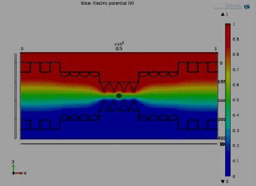
| Figure 1 depicts the potential distribution with the proposed 3D microchip where we find the non-uniform distribution of potential and intra cellular organelle also effect by this field. At pole θ=90° and θ=270° maximum potential are exposed which is similar as our numerical result. And complete electrical potential distribution within the 3D hybrid microchip where cell is affected through the whole channel. It also shows the graphical view of electrical potential distribution with respect to height of the bi metallic electrode within the 3D hybrid microchip. It explore that the center part (300-600) μm of the chip holds the maximum uniform potential where the nanopores are generated at the intraorganelle. Figure 1(b) shows the graphical view of polarization with respect to height of the bi metallic electrode within the 3D hybrid microchip which helps us to find out the maximum polarization area of nanopores. Maximum velocity excreted at the center of the chip, it affects the ion uptake of intra cellular unit of the rigid cell. All the information exposed in COMSOL simulation is as similar as numerical and experimental values of intraorganelle nanoporation of multilayer dense osteoblast cell. |
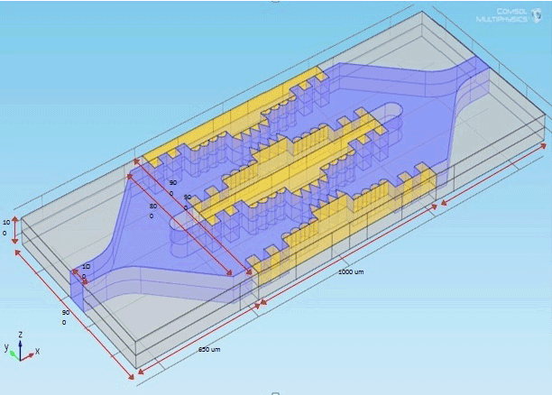
| Figure 2 shows the design parameter of microchip and the design values as given in Table 1. |
| The optimization value of pulse duration, interval and intensity for maximum efficient nanoporations are 5 ps 5 μs and 1 volts respectively. The complete dimension of the micro electrode and microchip & suspension media are explored in the Table 1. |
| Numerical simulation |
| In this study, above equations are solved numerically to find the electric potential developed in outer and inner membrane to investigate the creation of nanopores on the cell membrane. The MATLAB 7.2 and COMSOL 4.3a, commercial package was used in the numerical simulations. In order to discrete the solution domain, unstructured meshes were applied. The solution domain was broken into small meshes to allow meshes to fully cover the solution domain without overlapping. |
| Used parameter |
| Values for constants and parameters used in the simulations [16] are given in Table 2. |
| Results and Discussion |
| This part of our study dedicated to comparative study of intraorganelle nanoporations among the osteoblast cell and bone cancer cell placed in the integrated 3D hybrid microchip whose specifications are described in 5.3 and the synchronization among the COMSOL simulation, MATLAB numerical analysis and experimental observation. As we already explore the COMSOL simulation and experimental observations so remaining contribution are completed through the graphical representation of MATLAB simulations. This part evaluates the comparative study of different factors of the intraorganelle nanoporation of a dense osteoblast cell and cancer cell. |
| Intraorganelle potential |
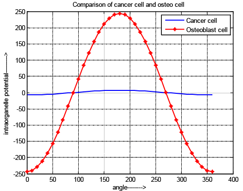
| The Figure 3 shows the comparative study of intraorganelle potential of osteoblast cell and cancer cell. It is observed that intraorganelle potential is exposed only when the pulse intensity & width are in picoscale range for normal osteoblast cell but in cancer cell it is above picoscale. In all cases the potential value is gradually decreases until the nanopores are generated and once the nanopores are generated, the potential starts to increase. The TMP has a sharper decrement at the poles (θ=0 and θ=360) It also exposed that the negative TMP is obtained at pole 0 to 89 and 271 to 360 due to the charging of membrane capacitor & positive voltage is obtained at poles 90 to 270 due to discharging. It is also reflects that for cancer cell the pole position of positive and negative are as same as normal osteoblast cell but amplitude is lower than previous cell due to the different chemical structure of the cell, reverse dielectric property and due to the higher elasticity of normal cell and presence of residual voltage. |
| In case of cancer cell nature of the graph is same as compare to normal cell but to activate the cell it required pico scale pulse for osteoblast cell and above pico scale for cancer cell and also potential value is less for cancer cell. It reflects that in same electric field the intraorganelle is more perforated which allows the maximum drug can be introduced in minimum effort. It shows that possibility of making the intraorganelle voltage greater than threshold voltage needs higher external voltage (near about 1.2 v) for intraorganelle pore generations. Nature of normal cell is more rigid than cancer cell and it also reveals that due to low rate of change of changing and discharging voltage the value of intraorganelle capacitive and resistive value of cancer cell is low, which reflects that the ion exchange possibilities and effect of rest potential is high. The results also reflect that rest potential of cancer cell has greater influences on intraorganelle potential. It prevents the ion exchange through the intraorganelle pores. |
| Intraorganelle pressure |
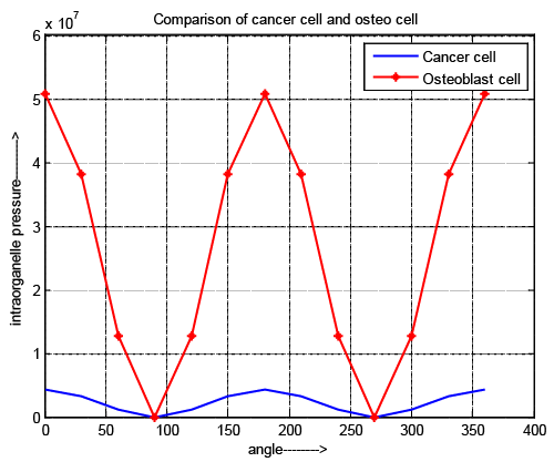
| It is shown in Figure 4 that the minimum and maximum value of osteoblast cell and cancer cell are located at the same polarity but maximum difference is observed in their numerical value. It reflects that the intraorganelle portion of cancer cell is more rigid than normal bone cell and easily changes its shape in irregular pattern. In our previous research it is explore that developed pressure can be changed by optimizing the applied pulse, changing the specification of microchip and the nature of suspension media for both cell. |
| Intraorganelle surface tension |
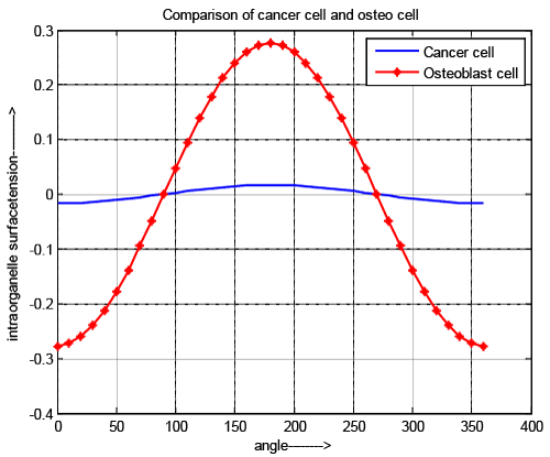
| As developed pressure and surface tension are directly related to each other, the nature of curves is same as shown in Figure 5. Figure 5 also supports that intraorganelle of cancer cell is more rigid than normal cell. |
| Intraorganelle pore current |
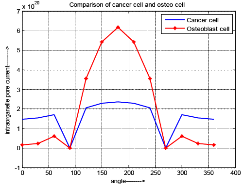
| Figure 6 depicts the variation of intraorganelle pore current for normal and cancer cell. The result explores that zero current is obtained at the poles (θ=90 and 270) for both cells. The pore current of cancer cell is greater during the pole θ=0-89 and θ=271–360. But during θ=91-269 pore current of normal osteoblast cell is higher compair to cancer cell. In this case pore current gradually decreases until the nanopores are generated and once the nanopores are generated, the above parameters start to increase. |
| Intraorganelle pore radius |
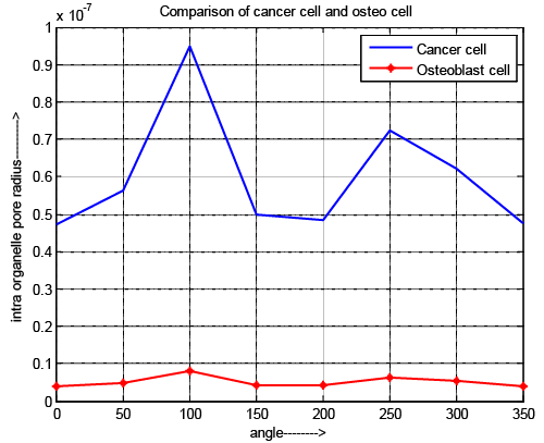
| Figure 7 depicts the variation of intraorganelle pore radius of osteoblast and cancer cell. In case of pore radius the pulse specifications have an acceptable effect because the requirement of pulse duration is 10-15 and 10-17 for normal cell and cancer cell respectable. Although, the maximum pore radius locate at the pole (θ=100 and 250) for all cell. It also exposed that the intraorganelle pore radius of cancer cell is greater than normal cell. The results reflect that intraorganelle of cancer cell is more flexible and having low elasticity compare to normal cell. If we control the specification of microchip as well as pulse then pore can be generated into the intraorganelle and it becomes more permeable than normal cell. |
| Intraorganelle pore density |
| Figure 8 depicts the variation of intraorganelle pore density of osteoblast and cancer cell. In case of pore density the pulse specifications have an acceptable effect because the requirement of pulse duration is 10-15 and 10-17 for normal cell and cancer cell respectively. Although, the maximum pore density locate at the pole (θ=100 and 250) for all cell. It also exposed that the intraorganelle pore density of cancer cell is greater than normal cell. The results reflect that if we control the specification of microchip as well as pulse then intraorganelle becomes more permeable than normal cell. This information provides a new idea about drug delivery system and cancer treatment. |
| Intraorganelle ion uptake |
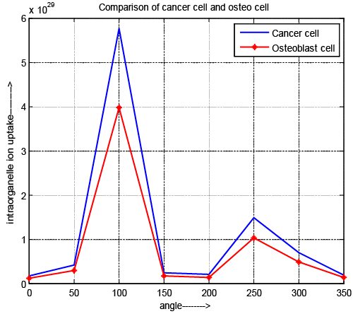
| Figure 9 depicts the variation of intraorganelle ion uptake of osteoblast and cancer cell. In case of ion uptake, the pulse specifications have an acceptable affect same as pore density. Although, the maximum pore density locate at the pole (θ=100 and 250) for all cell. It also exposed that the value of intraorganelle ion uptake is high for cancer cell. This result depicts that more drug can be introduced compare to normal cell. It also assigned that ion uptake of cancer cell is more controllable than normal cell with the help of specified microchip and pulse contribution which is designed. |
| Conclusion |
| The comparative study of intraorganelle nanoporation among osteoblast cell and bone cancer cell is carried under the influence of smart control picopulse generator in 3D hybrid microchip. The outcomes of the study are as follows. |
| I. Developed intraorganelle potential, pressure, surface tension as well as pore current of cancer cell is lower whereas pore density and radius are larger than normal osteoblast cell under 1 v DC short pulse so cancer cell requires high amplitude electric pulse to achieve its threshold voltages. It is found that the tumor cells showed lower intraorganelle potential and pore current compared to the normal cell. These results demonstrate the susceptibility of cancer cells to the electric field application and the relative robustness of the normal cells, illustrating the enhanced efficacy of the electro chemotherapy using lower drug doses. The electric field and polarity analysis results can be used for assessing effective treatment parameters of tumor cells. The electrical characteristics of intraorganelle, such as the surface tension, pressure and pore density also govern the response due to pulse specification, electrode geometry and material, micro channel dimension as well as nature of suspension media. |
| II. It is controlled by external user and the threshold pulse duration is 10-12 s and 10-15 s for normal cell and cancer cell respectively. |
| III. Pico electric field able to penetrate the intraorganelle membrane of cancer cell. |
| IV. It is shown that nearly 40% increase of nanoporation is observed in the tumor cell compared to the normal cell for a dedicated pico pulse in 3D advanced micro chip. |
| It is exposed that the electrical characterization of intraorganelle nanoporation among the normal and tumour cell are different because of abnormal structure of cancer cell. |
| In this research paper, it is found that parameter value of intraorganelle nanoporation such as potential, current, pressure, surface tension and pore density of cancer cell are non-uniform and lower than osteoblast cell which concludes that the cancer cells have no control of cell membrane transport and proliferation mechanisms as well as DNA activity, protein synthesis, and aerobic energy production. Since cancer cells cannot maintain a normal membrane potential, they will have electronic functions that will make repair and the re-establishment of normal metabolic functions. Therefore, a key therapeutic method for cell repair and cancer treatment would be to reestablish a healthy membrane potential in the body’s cells. Our results indicate that optimization of applied pulse, micro electrode, dimension of microchip and suspension media can control the intraorganelle nanoporative activity and ion uptake used for drug delivery system in effective treatment of bone cancer cell and also prevent side effect of chemotherapy. |
| Acknowledgement |
| All of we wish to thank Dr. Soumen Das (IIT, KGP) for assistance with analytical data processing throughout the whole work. |
References
|
Tables and Figures at a glance
| Table 1 | Table 2 |
Figures at a glance
 |
 |
 |
 |
 |
| Figure 1 | Figure 2 | Figure 3 | Figure 4 | Figure 5 |
 |
 |
 |
 |
|
| Figure 6 | Figure 7 | Figure 8 | Figure 9 |
Relevant Topics
- Analytical Biochemistry
- Applied Biochemistry
- Carbohydrate Biochemistry
- Cellular Biochemistry
- Clinical_Biochemistry
- Comparative Biochemistry
- Environmental Biochemistry
- Forensic Biochemistry
- Lipid Biochemistry
- Medical_Biochemistry
- Metabolomics
- Nutritional Biochemistry
- Pesticide Biochemistry
- Process Biochemistry
- Protein_Biochemistry
- Single-Cell Biochemistry
- Soil_Biochemistry
Recommended Journals
- Biosensor Journals
- Cellular Biology Journal
- Journal of Biochemistry and Microbial Toxicology
- Journal of Biochemistry and Cell Biology
- Journal of Biological and Medical Sciences
- Journal of Cell Biology & Immunology
- Journal of Cellular and Molecular Pharmacology
- Journal of Chemical Biology & Therapeutics
- Journal of Phytochemicistry And Biochemistry
Article Tools
Article Usage
- Total views: 10107
- [From(publication date):
March-2016 - Apr 18, 2025] - Breakdown by view type
- HTML page views : 9258
- PDF downloads : 849
