Research Article Open Access
Characterizing the Relationship between Carbon Dioxide Emissions and Vehicle Operating Modes on Roundabouts -A Pilot Test in a Single Lane Entry Roundabout
Shaojie Liu, Qing Li*, Fengxiang Qiao, Jianbang Du and Lei YuInnovative Transportation Research Institute, Texas Southern University, Houston, Texas, USA
- *Corresponding Author:
- Qing Li
Post-doctoral Fellow, Innovative Transportation Research Institute
Texas Southern University, 3100 Cleburne Street
Houston, Texas, 77004, USA
Tel: 713-313-7532
E-mail: liq@tsu.edu
Received date: March 28, 2017; Accepted date: April 03, 2017; Published date: April 09, 2017
Citation: Liu S, Li Q, Qiao F, Du J, Yu L (2017) Characterizing the Relationship between Carbon Dioxide Emissions and Vehicle Operating Modes on Roundabouts -A Pilot Test in a Single Lane Entry Roundabout. Environ Pollut Climate Change 1:120.
Copyright: © 2017 Liu S, et al. This is an open-access article distributed under the terms of the Creative Commons Attribution License, which permits unrestricted use, distribution, and reproduction in any medium, provided the original author and source are credited.
Visit for more related articles at Environment Pollution and Climate Change
Abstract
Roundabouts were initially installed to improve traffic flow and safety. However, the reduction may be not only limited to the idling duration. This research attempts to characterize the relationship between CO2 emissions and vehicle’s operating modes on a roundabout. An on-board emission pilot test was conducted on a one-lane-entry roundabout with four legs between Westcott Street and Washington Avenue in Houston, Texas, during peak and nonpeak hours of two consecutive weekdays. The test vehicle was a two-year old gasoline vehicle, which was equipped with a Portable Emission Measurements System (PEMS) to detect real-time exhaust emission rates from the tailpipe and estimate fuel consumption rates. A Global Positioning System (GPS) with magnetic force was placed on the roof of the vehicle to record vehicle’s dynamic geolocation, while an On-board diagnostic (OBD) II port was connected to the test vehicle collected real-time vehicle operation information, such as speeds. Results showed that 35 km/h approaching speed could minimize the CO2 emissions. Hard acceleration can lead to a spike in the CO2 emissions, while speeding by frequent small acceleration is beneficial to control the emissions. The longer route within the roundabout is in favor of fewer CO2 emissions. The vsp between 0 and 9 kw/ton and speed between 1.6 km/h and 40.2 km/h (1-25 mph) are identified as the typical feature of the vehicle operations on the roundabout.
Keywords
Roundabout; Greenhouse gas emissions; Anthropogenic CO2 emissions; Driver’s driving behaviors; Fuel consumption
Introduction
A greenhouse gas is referred to a gas in an atmosphere that absorbs and emits radiation within the thermal infrared range [1]. Atmospheric carbon dioxide (CO2) is one of the greenhouse gases. Most of today’s CO2 molecules will be removed from atmosphere by mixing into the ocean, photosynthesis, and other processes [2] in few decades, whereas the removal of the CO2 from the geological reservoirs, approximately 20%, may take many thousands of years [3-5]. In recent decades, anthropogenic CO2 emissions to the atmosphere have been growing rapidly. A total of 6,870 million metric tons of CO2 equivalent greenhouse gases were emitted in 2014 in the United States (US) and 81% of the total is CO2. The transportation sector is directly responsible for 26% of the anthropogenic CO2 emissions [6] and the transportation related emissions have been increasing by 45% in last two decades [7]. Particularly, burning fossil fuel by passenger cars accounts for 34% of the CO2 emissions from the transportation sector [8].
Many strategies have been implemented to reduce the CO2 emissions and improve fuel economy in vehicles, by vehicle designs, biofuels, road design, intelligent transportation system [9-14]. Regarding the road design, in recent decades, it has been proven that a modern roundabout is able to minimize the CO2 emissions by reducing vehicles’ idling duration [15]. The modern roundabout is a circular intersection or junction, in which road traffic flows almost continuously in one direction around a central island [16]. Drivers yield at entry to traffic flow within the roundabout. The roundabout was initially proposed to improve mobility and safety at intersections and demonstrated that it outperforms STOP sign controls and signalized intersection controls [17].
Additionally, Mandavilli [18] compared CO2 emissions before and after installing the modern roundabout and found that it enables vehicles to reduce vehicle idling duration, thereby improving traffic flow as well as diminishing CO2 emissions and fuel consumption. Another study by Hesh [19] estimated the CO2 emissions from vehicles on a roundabout and reported that compared with a signalized intersection, the modern roundabout can significantly reduce CO2 emissions and fuel consumption by 21.31% and 26.92%, respectively. This study supports that the CO2 emission reduction could be achieved by minimizing stopped delay time. It seems that shortening the idling duration is determinative for the CO2 emission reduction. However, a number of emission study results demonstrated that the CO2 emission is highly associated with vehicles’ operations [20,21].
Nevertheless, a vehicles’ operating pattern on roundabouts has been not yet explored and its association with the CO2 emissions is rarely investigated. These are essential for decision makers to design and install a modern roundabout that can maximize its benefits, in terms of the reduction in CO2 emissions, safety and mobility. This research attempts to characterize the relationship between CO2 emissions and vehicle’s operating modes on a typical modern roundabout by an onboard emission pilot test.
Methods
Vehicle operating mode on roundabout
In the most widely used emission model, Motor Vehicle Emission Simulator (MOVES), vehicle’s operations are classified into 23 operating mode bins to estimate exhaust emissions. Each bin is identified by vehicle’s instant driving speed (v), acceleration rates (a), and vehicle specific power (vsp). Table 1 shows the specific definition of the MOVES operating mode characteristics.
| Operating Mode ID | Operating Mode Description | Vehicle Specific Power, vsp (kW/ton) | Vehicle Speed, v (km/h) | Vehicle Acceleration, a (m/s2) |
|---|---|---|---|---|
| 0 | Braking | (at = -0.9) or (at = -0.4 and at-1 = -0.4 and at-2 = -0.4) | ||
| 1 | Idling | -1.6 = v<1.6 | ||
| 11 | Low Speed Coasting | VSP<0 | 1.6 = v<40.2 | |
| 12 | Cruise/Acceleration | 0 = VSP<3 | 1.6 = v<40.2 | |
| 13 | Cruise/Acceleration | 3 = VSP<6 | 1.6 = v<40.2 | |
| 14 | Cruise/Acceleration | 6 = VSP<9 | 1.6 = v<40.2 | |
| 15 | Cruise/Acceleration | 9 = VSP<12 | 1.6 = v<40.2 | |
| 16 | Cruise/Acceleration | 12 = VSP | 1.6 = v<40.2 | |
| 21 | Moderate Speed Coasting | VSP<0 | 40.2 = v<80.4 | |
| 22 | Cruise/Acceleration | 0 = VSP<3 | 40.2 = v<80.4 | |
| 23 | Cruise/Acceleration | 3 = VSP<6 | 40.2 = v<80.4 | |
| 24 | Cruise/Acceleration | 6 = VSP<9 | 40.2 = v<80.4 | |
| 25 | Cruise/Acceleration | 9 = VSP<12 | 40.2 = v<80.4 | |
| 27 | Cruise/Acceleration | 12 = VSP<18 | 40.2 = v<80.4 | |
| 28 | Cruise/Acceleration | 18 = VSP<24 | 40.2 = v<80.4 | |
| 29 | Cruise/Acceleration | 24 ≤ VSP<30 | 40.2 = v<80.4 | |
| 30 | Cruise/Acceleration | 30 = VSP | 40.2 = v<80.4 | |
| 33 | Cruise/Acceleration | VSP<6 | 80.4 = v | |
| 35 | Cruise/Acceleration | 6 = VSP<12 | 80.4 = v | |
| 37 | Cruise/Acceleration | 12 = VSP<18 | 80.4 = v | |
| 38 | Cruise/Acceleration | 18 = VSP<24 | 80.4 = v | |
| 39 | Cruise/Acceleration | 24 = VSP<30 | 80.4 = v | |
| 40 | Cruise/Acceleration | 30 = VSP | 80.4 = v |
Table 1: Definition of MOVES operating mode characteristics (US EPA [25]).

Figure 1: Average CO2 emission rate from a five-year old gasoline passenger cars (Frey and Liu [29]).

Figure 2: Entering review of the roundabout at Westcott St @ Washington Ave in Houston, Texas.
The vsp is the instantaneous power demand of a vehicle for motion divided by its mass. The power demand is subject to aerodynamic drag, acceleration, rolling resistance, grade, and the mass of the vehicle [22,23]. The vsp is a function of multiple factors, such as driving speed, acceleration rate, and road grade. As the test vehicle only executes one task of driving and other power-consumed devices are off, the power demand is mainly for vehicle’s motion purpose. In this case, the vsp is a function of driving speed, acceleration rates, and grades. The vsp estimation is expressed by Equation (1)
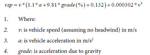
As the test site is on a plain, the grade was assumed as zero in Equation (1). Therefore, the vsp estimation is simplified as Equation (2) [8].

Taking CO2 emissions as an example, Figure 1 shows the distribution of the default average CO2 emission rates (g/s) on the Operating Mode Bin from a five-year old gasoline passenger car in the MOVES model.
In Figure 1, the lowest CO2 emission rates are observed in bins 0 and 1 for braking and idling mode. Between bins 11 and 40, there are three waves in the CO2 emission rates. The wave gradually increases steeper. For each wave, the CO2 emission rates increase steadily and then reach the spike in bins 16, 30 and 40. The CO2 emission rates from the spike drop significantly in the subsequent bin and restart the climb.
On-board emission tests
An on-board emission pilot test was conducted using a Portable Emission Measurement System (PEMS). A typical one-lane entry roundabout located at the intersection between Westcott Street and Washington Ave in Houston, Texas, was chosen for the test site. Figure 2 shows the horizontal view of the roundabout.
As Figure 2 shown, approaching vehicles to the roundabout are controlled by a YIELD sign at the entrance point indicated by a dash line. To avoid the interference of individual driving behaviors, one licensed test driver was recruited to drive through the roundabout towards three exits for multiple times during peak and nonpeak hours of two weekdays. For each round, the test driver drove through three segments, including approaching lane, within the roundabout, and leaving lane. Regarding the 3 segments and 3 exits, a total of 9 scenarios were designed and listed in Table 2.
| Scenario | Exits | Segment |
|---|---|---|
| S1 | 1st | Approaching Lane |
| S2 | Within Roundabout | |
| S3 | Leaving Lane | |
| S4 | 2nd | Approaching Lane |
| S5 | Within Roundabout | |
| S6 | Leaving Lane | |
| S7 | 3rd | Approaching Lane |
| S8 | Within Roundabout | |
| S9 | Leaving Lane |
Table 2: Scenarios design.
| Vehicle Information | Engine Information | ||
|---|---|---|---|
| Make | Toyota | Year | 2014 |
| Model | 4 Runner | Make | Toyota |
| Plate | DNT2862 | Model | 5vz-fe |
| Vehicle Weight | 6300 lbs | Displacement | 4,000 cc |
Table 3: Test vehicle specification.
The test routes for the six scenarios are illustrated in Figure 3. In Figure 3, the test driver departed from “Start” point on the approaching lane of Arnot St. Southeast-bound, about 200 m to the roundabout, for all scenarios. At the yield line, the driver yielded all traffic flow within the roundabout before merging. For S1-S3, the driver drove towards the first exit from the right direction; Westcott St. Southeast bound and ended at 200 m away the roundabout. The length of the on-roundabout was about 20 m for the first exit. Likewise, the end points for S4-S9 are located at about 200 m away the roundabout on individual leaving lane, namely Washington Ave Eastbound for the 2nd exit and Arnot St. Southwest bound for the 3rd exit. The on-roundabout lengths are approximately 60 m and 117 m for the 2nd and 3rd exit, respectively.
Table 3 shows the test vehicle’s specification, which information was input to the PEMS that was placed at the backseat of the test vehicle. The screenshots of the test vehicle and the in-vehicle PEMS are shown in Figure 4.
While the PEMS was connected to the On-Board Diagnostics (OBD) port of the test vehicle for real-time vehicle operation information, such speed, a global positioning system (GPS) device with magnetic force was placed on the roof of the vehicle to record vehicle’s real-time geo-location, including longitude, altitude, and latitude. Vehicle’ acceleration rates were calculated based on the speed collected from the OBD. Meanwhile, the exhaust from the tailpipe was sucked to the gas condenser then to the gas analyzer of the PEMS for real-time emission rates of a specific emission. The real-detected CO2 emissions by the PEMS were monitored for this study.
Data process
The PEMS collected data includes second-by-second CO2 emission rate in g/s, driving speeds (v) in m/s, Geo-location, and fuel consumption rate in g/s, at a time domain. The distribution of the CO2 emission pattern and the variability of samples indicated by interquartile range (IQR), were visualized by a boxplot. The time domain emission rates and Fuel Consumption (FC) on the routes were interpolated to meter-by-meter distance domain for the comparison of the emissions on each segment.
Meanwhile, the driving speeds were calculated to acceleration rates. The vsp was further estimated using the speed and acceleration rates. Together with the vsp, speed, and acceleration rate, the test vehicle’s operating mode bins were classified according to the definition of MOVES operating mode characteristics shown in Table 1.
Results and Discussion
Distribution of CO2 emissions on segments
Figure 5 illustrates CO2 emission distribution on the three segments while driving towards the three exits.

Figure 3: Layout of the test route.

Figure 4: Test vehicle equipped with a PEMS.
The CO2 emissions on the roundabout range from 0.1 g/s to 0.7 g/s. Apparently, the CO2 emissions on the approaching lane for the 2nd and 3rd exit are much denser at the lowest level, indicating by smaller IQR (shorter box). Meanwhile, there are more outliers denoted by the red crosses on their boxes. Besides, as this is a one-lane entry roundabout, the test vehicle’s operation on the approaching lane shall not be subject to the subsequent exit selection. However, the CO2 emissions obviously vary with each test. It is worth noting that the driving tasks on the approaching lane are more complex than on other lanes. The driving task could include deceleration, possible idling for an acceptable gap, timely acceleration for merging into the traffic flow, which highly depends on traffic flow in the roundabout. Therefore, the difference in the CO2 emission distribution on the approaching lane may be attributed to the complex vehicle operation. The dense samples distribute at the bottom implies that the test vehicle more often idle at the dash line for yielding vehicle flow. The median levels (red line in the box) of the CO2 emissions on the approaching lane are relatively close to each other and lower than those in other scenarios.
Within the roundabout, speeding up and maintaining a driving speed as the flow within the roundabout could be the main driving task. While the higher variability of the CO2 emission rates is observed in the scenarios for the 1st exit, the higher median level is the ones for the 2nd exit. The difference in the CO2 emissions among the scenarios for the three exits is the driving speeds and the length of the test routes within the roundabout. The test route for the 3rd exit is the longest with 117 m and its median level is the lowest, whereas the highest median level is found on the second-long test route towards the 2nd exit. This excludes the impacts of the route length on the CO2 emissions.
On the leaving lane, rare emission samples are observed at the bottom, which means the test vehicle did not idle at the exit. Therefore, maintaining the driving speed is the main driving task. The CO2 emission distribution within and leaving the roundabout reflects the difference in the maintained traffic flow speeds.
CO2 emission pattern on a roundabout
Figure 6 shows the CO2 emission and FC profiles while driving through the roundabout towards the three exits. The yield line in Figure 3 was set as zero distance on x-axis. The signs “-” and “+” in represent the direction of approaching and leaving the yield line, respectively, while the shadows indicate the variation area of the CO2 emission and FC factors. The purple dash lines separate the route into three segments. The negative distance is on the approaching lane, while the on-roundabout lane lies in between the two purple dash lines. The leaving lane is right after the on-roundabout lane on positive distance.

Figure 5: CO2 emission rate distribution on the segments of the roundabout.

Figure 6: CO2 emission factor and FC factor distribution on three exits.
As a whole, the trend lines CO2 and FC as well as their variations are almost overlapped throughout the profiles. As all carbon-based fuel in a vehicle is intentionally converted to CO2 to release energy, the overlapping profiles imply that there is no visible difference in the test vehicle’s fuel efficiency among the scenarios. Besides, the overall emission factors on the longer test route towards the 3rd exit are lower than those on the shorter routes towards the 1st and the 2nd exits.
There is a common trend on the approaching lane before entering the roundabout. The CO2 decreases gradually from -100 m away to the roundabout, and reaches the lowest emission point at about -60 m, then spikes to another higher level before the yield line (0 m on x-axis). This pattern is in accord with the driving tasks with the sequence of deceleration, idle, and then acceleration, on the approaching lane. Besides, before the yield line, there was only one spike on the approaching lane between –60 m and 0 m for the 2nd and 3rd exit, while there were two spikes for the 1st exit. The exclusive CO2 emission spike for the 2nd and 3rd exit might explain the outliers in Figure 5.
Within the roundabout, the emission variation for the 1st exit was apparently larger than for other exits, which was also reflected by the longer IQR in Figure 5. For the 2nd and 3rd exits, the overall CO2 emissions are stable at a certain level within the roundabout. Before leaving the roundabout, another spike presented and then gradually declined afterward.
Vehicle operating patterns on a roundabout
Figure 7 demonstrates the speed and acceleration profiles while driving through the roundabout.
On the approaching lane, the acceleration profiles in green fluctuated frequently and hardly than those on other segments. A gradual deceleration was operated before -60 m and subsequently two harder accelerations at about -20 m and around the yield line to the roundabout, respectively. The corresponding speed in red for the 2nd and 3rd exits declined sharply, whereas the speed for the 1st exit performed differently. For the 1st exit, about 28 km/h was maintained and then it increased for a while and sharply decreased before entering the roundabout. It was noticed that the starting speed from -100 m for the three exits were not consistent. The starting speeds were 28 km/h, 35 km/h, and 32 km/h, for the 1st, 2nd and 3rd exits, respectively. The lower starting speed for the 1st exit enabled the speeding to react gently preparing the upcoming yield control. Recalling the lower emission distribution on the approaching lane for the 2nd and 3rd exits in Figure 5, the approaching speed of 35 km/h was in favor of emission reduction and fuel consumption efficiency. Besides, instead of two spikes, the two hard acceleration actions for the 1st exit brought about higher variation for the shorter duration and travel distance between them before merging the traffic flow. For the 2nd and 3rd exits, the harder accelerations would be responsible for the emission spikes mentioned above.
Within the roundabout, frequent small acceleration actions were operated for the 2nd and 3rd exits, which could control the emission at the certain level mentioned above. However, it seems that the emission variation for the 1st exit does not react in this way. This may be due to the shorter route length and the flow speed. The red speed lines in Figure 7 performed a gradual rise for the three exits. At the exit point, the common speed was 30 km/h, which indicates the flow speed within the roundabout. Variant maneuvers of speeding up from 22 km/h to 30 km/h at the shorter distance with 20 m, for the 1st exit could account for its longer IQR or higher variation.

Figure 7: Vehicle��?s speed and acceleration profiles on roundabout.

Figure 8: Distribution of vehicle��? operating bins on approaching, within, and leaving the roundabout from three exits.
The speed continued to increase on the leaving lane, while the corresponding acceleration lines kept stable. On the other hand, the CO2 emissions in Figure 6 overall fluctuated within a certain level. In other words, higher driving speed could be accompanied with lower CO2 emissions for higher fuel efficiency and the CO2 emissions were sensitive to acceleration rates, rather than the speed.
Features of operating modes on roundabout
Figure 8 shows the distribution of the test vehicle’s operation modes while driving through the roundabout towards three exits. As the test vehicle’s operation modes distributed from bins 0 to 25, the limit of the x-axis was set to bin 25 in Figure 8. Based on Figure 1, the lowest CO2 emission rates were observed in bin 0 and 1 represented biking and idling modes. Figure 8 shows that about 20-28% of operating time were spent on the braking mode on the approaching lane for the three exits, and no idling was operated. Within and leaving the roundabout, rare braking and idling were operated.
Generally speaking, most operating information fell into the lower CO2 emission wave between bins 11 and 16. In particular, more than 90% of driving time the test vehicle was operated at a lower speed (<40.2 km/h) and a lower vsp (<9 kw/ton), within the roundabout for the three exits. Specifically, the test vehicle was mostly under the operating modes between bins 12 and 14, ranging from 41% for the approaching lane towards the 2nd and 3rd exits (Figures 8d and 8g); to 100% within the roundabout towards the 2nd exit (Figure 8e).
Only a small portion of driving time was spent on the operating modes between bins 21 and 24. However, Figure 1 demonstrated that the CO2 emission rates in such bins were almost equal to the emission levels in bins 12 to 14. Therefore, the overall emission levels on the roundabout were comparable to the first CO2 emission wave in Figure 1.

Figure 9: Time distribution to the operating mode IDs for the three exits.
In terms of exit selection, Figure 9 illustrates the time distribution to the Operating Mode IDs. Obviously, a greatest proportion of the driving time was occupied by the bins between 12 and 14, with 59%, 74% and 73%, for the three exits, respectively, followed by bins 0 and 1 for the braking and idling modes, and bin 11 for low speed coasting. In other words, vsp between 0 and 9 kw/ton and speed between 1.6 km/h and 40.2 km/h (1-25 mph) were the typical feature of the vehicle operations on the roundabout.
Conclusion
An on-road pilot emission test was conducted in a typical one-lane entry roundabout in Houston, Texas, using PEMS. Real-time emission rates, fuel consumption rates, and vehicle’s operation information were collected while driving through the roundabout towards different exits. The test vehicle’s CO2 emissions were compared among 9 scenarios on three segments, including an approaching lane, within the roundabout, and the exiting lanes linked with the roundabout (leaving lanes). It was found that usually one deceleration, two acceleration actions are required before merging into the traffic flow in the roundabout. 35 km/h approaching speed could minimize the CO2 emissions on lanes. Hard acceleration can lead to a spike in the CO2 emissions, while frequent small acceleration for gradual speeding is beneficial to control the emissions within a certain level. The higher CO2 emission and variations are observed at the shorter route and the CO2 emissions are sensitive to acceleration. The overall emission level on the roundabout are comparable to the lower CO2 emission level shown in Figure 1. Operating Mode Bins 12 to 14 was identified as the typical feature of the vehicle operation on the roundabout.
Acknowledgement
The authors acknowledge that this research is supported in part by the National Science Foundation (NSF) under grants #1137732. The opinions, findings, and conclusions or recommendations expressed in this material are those of the author(s) and do not necessarily reflect the views of the funding agencies.
References
- Baede APM, Van der Linden P, Verbruggen A (2007) IPCC AR4 SYR appendix glossary.
- Archer D (2009) Atmospheric life time of fossil fuel carbon dioxide. Ann Rev Earth Planet Sci 37: 117��?134.
- Meehl GA (2007) Frequently Asked Question 10.3: If emissions of greenhouse gases are reduced, how quickly do their concentrations in the atmosphere decrease? In S. Solomon; et al. Chapter 10: Global Climate Projections. Climate Change 2007: The Physical Science Basis. Contribution of Working Group I to the Fourth Assessment Report of the Intergovernmental Panel on Climate Change. Cambridge University Press (CUP), Cambridge, United Kingdom and New York, USA.
- Chapter 10: Global Climate Projections
- Archer D (2005) Fate of fossil fuel CO2 in geologic time. J Geophys Res 110: C09S051��?6.
- Caldeira K, Wickett ME (2005) Ocean model predictions of chemistry changes from carbon dioxide emissions to the atmosphere and ocean. J Geophys Res. 110:1��?12.
- International Transport Forum. Reducing Transport Greenhouse Gas Emissions: Trends and Data. Paris: Organisation for Economic Co-operation and Development, 2010.
- United States Environmental Protection Agency (EPA) (2016)
- Li Q (2016) Impact of freeway weaving segment design on environment and public health. Doctoral Dissertation, Texas Southern University.
- Li Q, Qiao F, Yu L (2016a) Vehicle emission implications of drivers smart advisory system for Traffic operations in work zones. J Air Waste Manag 66: 446-455.
- Li Q, Qiao F, Yu L (2016b) Clustering pavement roughness based on the impacts on vehicle emissions and public health. Ergonomics 6: 1-4.
- Munni J, QiaoF, Li Q, Yu L (2015) Driving Behavior and Emission Analysis at Yellow Interval with Advanced Warning Message under Foggy Weather Condition: A Simulator Test. Proceedings of the 56th Annual Transportation Research Forum in Atlanta, GA, USA.
- Li Q, Qiao F, Yu L (2016c) Modeling Texas Emission Factors Considering Pavement Roughness Using On-board Emission Measurement. Proceedings of the 109th Air and Waste Management Association (AWMA), New Orleans, LA, USA.
- Rahman R, Qiao F, Li Q, Yu L, Kuo P-H (2015) Smart Phone Based Forward Collision Warning Message in Work Zones to Enhance Safety and Reduce Emissions. Proceedings of the 94th Transportation Research Board Annual Meeting, Washington, DC,USA.
- Li Q, Qiao F, Yu L. (2015) Will vehicle and roadside communications reduce emitted air pollution? Int J Sci Technol 5: 17-23.
- Bronw L (1993) The New Shorter Oxford English Dictionary, Volume 2, Clarendon Press, Oxford, p: 2632.
- Crown B (2001) Report on roundabouts.
- Mandavilli S, Russell ER, Rys MJ (2003) Impact of modern roundabouts on vehicular emissions. In Proc, 2003 Mid-Continent Transportation Research Symposium.
- Mandavilli S (2003) Environmental impact of Kansas roundabout, In Proceedings of Annual Conference of the Transportation Association of Canada.
- Li Q, Qiao F, Yu L (2017) Nonlinear models of light-duty vehicle emission factors considering pavement roughness. J Civil Environ Eng.
- Hesch M (2007) Quantitatively determining the emissions reduction benefits of the replacement of a signalized intersection by a roundabout, Academy of the Holy Name, Albany, NY.
- Qiao F, Li Q, Yu L (2014) Testing Impacts of Work Zone X2V Communication System on Safety and Air Quality in Driving Simulator. in Proceedings of the 21st ITS World Congress, Detroit, MI, USA.
- Jimenez-Palacios JL (1999) Understanding and Quantifying motor vehicle emissions with vehicle specific power and TILDAS remote sensing. Ph.D. Dissertation, Massachusetts Institute of Technology, Cambridge, MA
- Pease, K. (2009) Vehicle Range Finder, U. S. Patent; US20100138142 A1, US 12/504,810. New World Encyclopedia. Combustion.
- Frey HC, Liu B (2013) Development and evaluation of a simplified version of MOVES for coupling with a traffic simulation model. The Transportation Research Board 91st Annual Meeting Compendium of Papers. Paper.
- United States Environmental Protection Agency (EPA) (2011) Development of emission rates for light-duty vehicles in the motor vehicle emissions simulator (MOVES) (2010), Final Report EPA-420-R-11-011.
Relevant Topics
Recommended Journals
Article Tools
Article Usage
- Total views: 4388
- [From(publication date):
April-2017 - Jul 15, 2025] - Breakdown by view type
- HTML page views : 3431
- PDF downloads : 957