Research Article Open Access
Bench Structural Integrity Modeling of Oil Sands for Optimum Cable Shovel Performance
Eric Gbadam and Samuel Frimpong*Department of Mining and Nuclear Engineering, Missouri University of Science and Technology, USA
- *Corresponding Author:
- Samuel Frimpong
Professor and Chair, Department of Mining and Nuclear Engineering
Missouri University of Science and Technology, USA
Tel: 573-341-4753
Fax: 573-341-6934
E-mail: frimpong@mst.edu
Received Date: January 21, 2014; Accepted Date: February 03, 2014; Published Date: February 10, 2014
Citation: Gbadam E, Frimpong S (2014) Bench Structural Integrity Modeling of Oil Sands for Optimum Cable Shovel Performance. J Powder Metall Min 3: 120. doi: 10.4172/2168-9806.1000120
Copyright: © 2014 Gbadam E, et al. This is an open-access article distributed under the terms of the Creative Commons Attribution License, which permits unrestricted use, distribution, and reproduction in any medium, provided the original author and source are credited.
Visit for more related articles at Journal of Powder Metallurgy & Mining
Abstract
The ultimate bearing capacity of bench and haul road formations are essential for the health and longevity of shovel crawlers. In soft saturated formations (especially in the Athabasca oil sands formation), heavy machines have been known to sink, resulting in production losses and high operating costs. Companies have solved these problems by widening the shovel crawlers to reduce average stresses on the formation, which may also be costly. In this study, the authors provide a solution to this problem using fundamental research. The Buisman-Terzaghi model is used to develop bench/haul road bearing capacities and their structural integrity within an oil sand formation at an environmental temperature of 25°C. A 3D finite element (FE) model of the formation is developed in ABAQUS to examine the average stresses and deformations on the formation at static equilibrium. The results show that the deformation of oil sand occurs during the first 30 seconds of crawler interaction. Two distinct regions were observed from the plastic strain failure pattern: the region below the tracks has larger strain at failure, and the regions adjacent the tracks expand deeper and wider in all directions. Failure of the formation was observed to occur mostly under the tracks and this progress non-linearly to the base of the formation. These failure patterns were triangular in nature and agree well as reported in Terzaghi’s early work on shallow foundation. The deformations were observed to be non-linear. The maximum static deformation of 2.497 cm was observed at the crawler-ground interface during the interaction. Future works would include a virtual prototype of cable shovel crawler-oil sand interaction to measure real-time stresses; crack initiation and propagation under dynamic conditions.
Keywords
Cable shovel; Finite element analysis; Bench structural integrity modeling; ABAQUS; Static and dynamic bearing capacity
Nomenclature
| B | footing width | Ø | soil internal friction angle |
| c | cohesion | γ | unit weight |
| NC,Nq,Nγ | bearing capacity factors | qs | surface surcharge |
| qu | ultimate bearing capacity |
Introduction
Oil sands (or soft formation) conditionsare the most important considerations in evaluating equipment performance with respect to providing adequate bearing capacity during operation of large mobile equipment like cable shovels [1]. Cable shovel is the primary choice of equipment used in the oil sand industry for overburden and oil sand excavation due to its high breakout force, large dipper capacity, low production and ownership cost. There is a growing demand for high capacity mining machinery including cable shovels with advent effect of increase in Gross Machine Weight (GMW). Current cable shovels have capacities of 105 ton passes. With the increase in dipper capacity, the forces that the shovel exerts on the oil sands formation increase significantly. These forces are distributed non-uniformly along the length of the tracks in a trapezoidal pattern. The payload and cyclic loading nature of this machine are transferred to the oil sand formation via the crawlers. This dynamic loading reduces the oil sand shear strength and causes instability. The structural integrity of the oil sand formation bench is a critical parameter that determines the failure of the benches/haul road under imposed GMW of cable shovels.
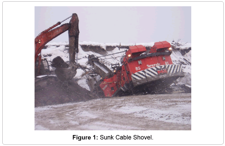
The stability of bench and haul road formation and the potential for its failure is a major concern because of the effect on the safety of personnel and equipment. Additionally, bench failure results in production losses and increased downtime. Figure 1 shows a sunk cable shovel in the Athabasca Oil Sands Formation due to average stress exceeding bench formation ultimate strength.
Oil sands are naturally occurring geologic formations that contain a mixture of water, clay, sand, and thick heavy oil called bitumen. Currently, 20% of the oil produced from Canadian oil sands formations are obtained through surface mining. Oil sand formation often experience varying magnitudes of static and dynamic loads applied in vertical and horizontal directions during mining operations using cable shovels in the mining bench. It has been observed that the cyclic nature of the cable shovel in the oil sands operations causes the material underfoot the crawler to deteriorate [2] providing a less ideal foundation for the equipment. The structural integrity of the formation through the ultimate bearing capacity should exceed the average stress due to machine weight on the crawlers to prevent shovel sinkage or shovel bench failures. The load bearing capacity of oil sands is low due to the composition (typically 8% to 15%) of the weight of bitumen content in the formation.
Additionally, high static and cyclic loads from the mining equipment and changes in ambient temperature (viscosity of bitumen) during summer and winter are other major factors that control bearing capacity of the formation [3-5]. Joseph and Shi [4] reported that during the summer times, mining equipment like cable shovels subject the oil sands to unload-reload cycles, causing progressive strength reduction by cycle. Under cooler ambient conditions, oil sand is more compact and thus undergoes increasing cycles and behaves as a stiff material showing little deformationcompatible with increasing cycles undergoing little deformation. Consequently, the structural stability of the formation is significantly reduced when heavy haul trucks, shovels and other mining equipment operate on it. Joseph et al. [3] and Sharifabadi and Joseph [6,7] observed that trucks and shovels operating on these soft materials in summer were faced with sinkage (rutting) and traffic ability problems.
The outcome of shovel sinkage is in the form of carbody and side frame cracks, and associated increased downtime, maintenance cost and subsequent reduced availability [2].Thus, the bearing capacity of the oil sands foundation on which this equipment operatesiscritical in the long-term formation stability and optimum performance of the cable shovel.
There are a number of methods in widespread use for determination of a soil’s ultimate bearing capacity under shallow and surface footing foundations. These methods include the classical bearing capacity equation [1], elastic method [8] and elastic-plastic method [9]. A number of investigators over the years have researched into foundation bearing capacity.
Typically, the classical theories of elasticity and plasticity in soil behavior have been used [10].Using the theory of plasticity [10], studied the effect of a long, narrow metal tool bearing against the surface of a smooth metal mass that possessed cohesion and internal friction but no weight. Reissner extended Prandtl’swork by including a bearing area below the surface of the resisting material; and a surcharge weight that acts on a plane level with the bearing area. Terzaghi [1] extended both theories to soil foundation problems. In his work, consideration was given to rough foundation surfaces bearing on materials that possess weight assuming general shear failure mechanism.In practice, the bearing capacity of a shallow strip footing resting on a single homogenous layer is determined by using the Terzaghi [1] classical equation:
 (1)
(1)
Equation (1) has been modified by various researchers to account for different footing shapes, depth and load inclination [3], mode of shear failure inclined or eccentric loading. Meyerhof and Meyerhof and Hannaused a punching shear failure mechanism to derive the ultimate bearing capacity of a footing on a granular layer overlying a clay deposit with untrained cohesion. The results showed that the net ultimate bearing capacity of the clay layer is independent of its location.
Recently, the finite element (FE) method has proved to be a powerful computational tool to analyze the ultimate bearing capacity of different soil formations under various loading conditions. This computational method provides advantages over the classical approach such as its ability to deal with nonlinear analysis. Benmebarek et al. [11], Griffiths [12], Burd and Frydman [13], Zhu [14] used convectional FE analysis to predict bearing capacity of multilayered soils.
Griffiths [12] computed the bearing capacity factors of footings resting on c-Ø soils using FE in conjunction with plasticity theory. The results gave accurate bearing capacity predictions for a wide range of homogenous soil. Nasr (2009) carried out an experimental and numerical study to determine bearing capacity of strip-footing on oilcontaminated sand. The results obtained by the experimental analysis were validated computationally using a plain-strain elastoplastic FE model with an interface gap element between footing and the soil. The results obtained from both the theoretical and numerical studies were found to be reasonably good in terms of load-settlement behavior.
Limited studies have been carried out to determine the bearing capacity of oil sands under cable shovels. Previous major works includes using the classical bearing capacity equation used for shallow foundations to calculate bearing capacity of crawler cranes on soils [15]. Recently, Joseph and Shi [4] developed a predictive model for a 2,230-tonne mobile in-pit hopper/crusher for operation in the Canadian oil sands to evaluate bearing capacity. The model was used to evaluate peak track or pad ground-bearing pressures and resulting ground deformations. Numerical modeling and field studies have been carried out to study the allowable bearing capacity of soils for mobile crawler cranes [15].
Using the traditional bearing capacity proposed by Terzaghi [1] for shallow foundations would lead to conservative design. Thus, the authors modified the equations for the traditional bearing capacity calculation used for shallow building foundations to predict the allowable bearing capacity accounting for the uneven pressure distribution under the crawler tracks. Whereas the work of Liu et al. [15] provided useful insights and tools to determine bearing capacity of crawler cranes in soil, their research considered only 2D plane-strain conditions. The advantage of using 2D plane-strain model is faster computational time. However, the major limitation of this method is inability to handle lateral loads. In addition, the 2D model is not suitable for more complicated contact like shovel crawler-oil sand interface.These limitation makes modeling the shovel crawler interaction in 2D plane-strain conditions more conservative. To overcome these limitations, 3D FEM have been used by other authors to model interaction between oil sand terrain and pipe wagon articulating system [8]; and contact and soil interaction with a rigid wheel [16]. The interaction of shovel crawlerswith oil sands formation is a unique phenomenon, undergoing both horizontal and vertical loads, that requires further investigations in 3D model considerations. Oil sand materials have very little tensile strength similar to soils and become permanently deformed under compressive loads. These tendencies make any modeling effort including oil sand interaction non-linear in nature. Non-linear problems typically require the use of large numbers of finite elements which produce very long computational times [17].
The objective of this work was to develop a 3D nonlinear FE model of cable shovel crawler-bench interaction to examine the ultimate bearing capacity of the formation; deformations and stresses beneath the crawler-ground interface. The authors have developed a non-linear FE model to predict oil sands bearing capacity within a 3-D coordinate system to account for both vertical and lateral effects. This model accounts for the contact forces between the crawler shoes and the oil sands formation, as well as the temperature changes during summer and winter. Additionally, the effects of the two tracks acting as multiple footings on the formation can easily be predicted in the 3D model.
A 3D Finite element model (FEM) of the formation was developed in ABAQUS [17] software due to its strong capabilities in dealing with nonlinear problems to examine the average stresses on the formation during shovel crawler-ground interaction. The model accounts for both contact and material nonlinearities. The P&H 4100XPC cable shovel machine configurations were considered for this study. Theoretical and numerical modeling methods are considered to model the structures and behaviors of benches under external static loading from cable shovels. The theoretical equations by Buisman-Terzagh iformed the foundation for developing the shovel bench/haul road bearing capacity models. These models will determine the static bearing capacity, deformations and stresses of the oil sands at an environmental temperature of 25°C. This study is significant because it provides a solid foundation for further study of cable shovel crawler-bench interactions in oil sand formations excavation.It also provides a quick numerical check for computing the average stress from heavy machines on any weak saturated formation.
The next sections would describe the FE modeling. This will include the FE problem definition, material constitutive model for oil sands, geometry and the boundary conditions of the crawler-formation interface. Model validation and the results and discussion would be given in section 4 and 5 respectively.
Shovel Crawler-Oil Sands Interaction Problem
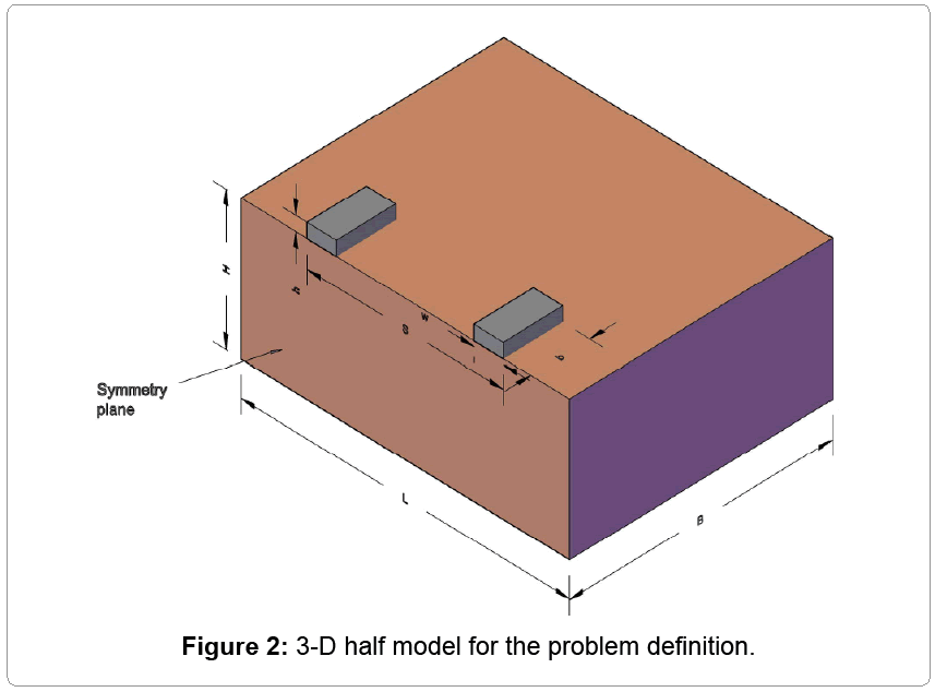
The 3-D bearing capacity problem of oil sands for cable shovel is shown in Figure 2 and listed in Table 1. A track of width w rests upon the oil sand layer of shear strength cos and thickness H. The dimensions of the oil sand material model are chosen so as to minimize the boundary effect on formation behavior. Due to the assumed uniform distribution of pressure under the crawler tracks, half symmetry model is exploited in the simulation to reduce computational time. The loaded area simulates a footing (or track) with perfectly rough contact with oil sand by specifying a tied contact constraint at the track/oil sand interface.
| L (m) | B (m) | H (m) | S (m) | W(m) | b (m) | h (m) |
|---|---|---|---|---|---|---|
| 25 | 20 | 10 | 10.5 | 2.21 | 4.5 | 1 |
Table 1: Dimensions of a cable shovel crawler.
Oil Sand-Shovel Crawler Interaction Model
The crawler track is modeled as a rigid rectangular footing made of mild steel. Each track (left and right) of the P&H 4100XPC shovel consists of 15 shoes in contact with the formation, 9 m long, 2.21 m wide and 1 m thick. The contact interaction is modeled as Coulomb friction criterion (Eqn. 2) to describe friction at the track-oil sand interface. The model relates the maximum allowable frictional (shear) stress across an interface to the contact pressure between the contacting bodies. The size of the FEMis large enough to keep boundary conditions at the bottom and symmetry plane from restricting the oil sand movement during crawler interaction.
 (2)
(2)
Oil sands material model
The unique nature oil sands calls for a suitable geological material model that can specifically capture most of the parameters of oil sands. Samieh andWong [18] have studied the geomechanical behavior of oil sands at various confining pressures and ambient temperatures. Using an extensive experimental data from drained triaxial tests on oil sands, Wan developed a constitutive model for oil sand which embraces most of the basic characteristics of the material. Recently, Li [19] analyzed and simulated laboratory tests data provided by different researchers to obtain a representative geomechanical model of oil sand material. The results show that a strain softening Mohr-Coulomb model can be considered as a representative model for oil sands material. In this work, elastoplastic model of the material undergoing strain softening Mohr-Coulomb’s failure is used in ABAQUS [17] for the research.
The Mohr-Coulomb plasticity model is used to model materials with classical Mohr-Coulomb yield criterion and allows the material to harden and/or soften isotropic ally. The criterion assumes that yield occurs when the shear stress on any point in a material reaches a value that depends linearly on the normal stress in the same plane. The Mohr- Coulomb model is defined by [17]:
 (3)
(3)
σ is negative in compression. The yield criterion of this model is defined as follows:
 (4)
(4)
The tension yield function has the form:
 (5)
(5)
Strain softening aspect of the material model is a development of the Mohr-Coulomb criterion with the non-associative flow rule (Equation 6) used to define shear plastic flow and an associated flow rule (Equation 7) used to define tensile plastic flow respectively:
 (6)
(6)
 (7)
(7)
Table 2 gives the parameters used for the oil sand in the simulation.
| ρ (kg/m3) | σy(MPa) |
E (MPa) |
ν | ET (MPa) |
T (°C) |
Ø(°) |
c (kN/m2) |
ψ (°) |
|---|---|---|---|---|---|---|---|---|
| 1600 | 0.1 | 10 | 0.3 | 0.1 | 25 | 30.67 | 10 | 10 |
Table 2: Oil sand properties.
FE model of oil sands deformation
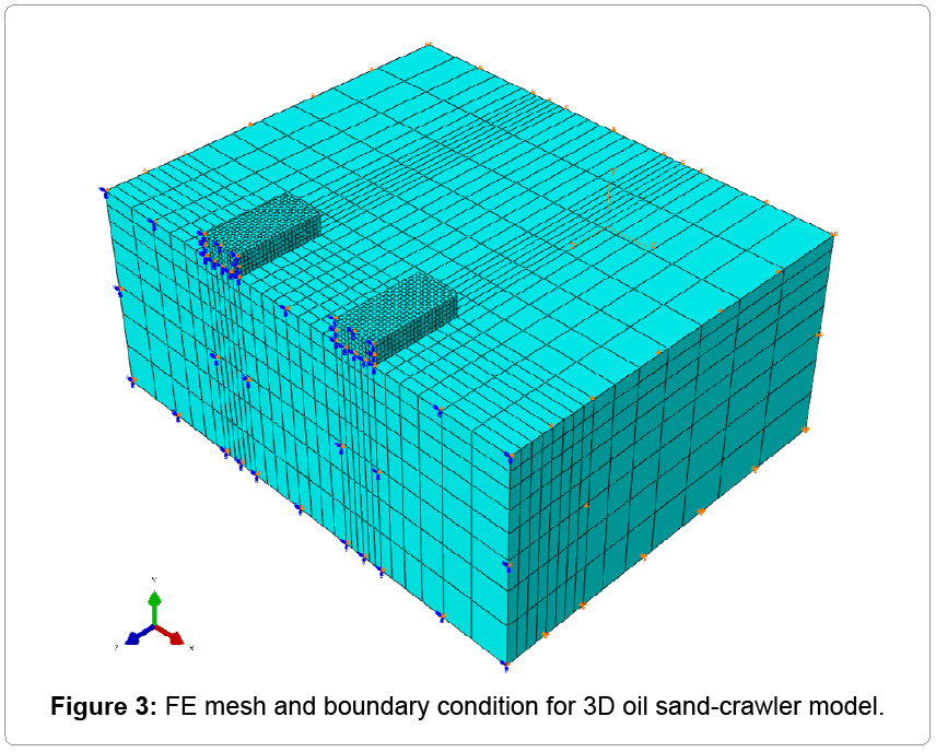
The FE mesh is shown in Figure 3 with different mesh density for the tracks and oil sand, tied together using surface contact. The meshes under the track are finer since that zone is a stress concentration domain. The elements selected for both oil sand and track were “C3D8R”, 3D, 8-node linear brick. This type of element supports only the three translation degrees of freedom in the given x, y, z directions. The C3D8R uses reduced integration technique to solve the problem, which greatly reduces computation time at the expense of element stability. The base of the oil sand is fixed in all directions. All vertical boundaries are fixed in the perpendicular direction but free in the vertical direction. All nodes along the plane of symmetry were given the “ZSYMM” condition. This translates to fully constraining “z” displacement and rotation about “x” and “y” axes.
Terzaghi’s [1] classical bearing capacity equationforms the foundation for this work. An overburden pressure (Equation 8) is used in the model to account for the depth of influence (Equation 9) so as to ignore the shear resistance created by this thickness, Df.
 (8)
(8)
 (8)
(8)
Load-displacement curve for the track underfoot is plotted. The bearing capacity of the oil sand-crawler interface is then obtained from the load-displacement curve. The analysis is performed using static numerical formulation. The loads are applied very slowly to avoid exciting the model. In the beginning of the analysis, gravity and surcharge loads are applied to the oil sand material to initiate the induced stresses in all the oil sand elements. The loads are applied using a constant downward velocity boundary condition at the top surface of the model, for duration of 10 seconds.
Model Verification and Validation
Verification is the process which confirms that the model and its implementations accurately behave the way it was intended according to the modeling assumptions made. The 3D ABAQUS model was verified through debugging techniques and was found to be satisfactory. Validation is the process of making certain that the simulation model accurately represents the actual system. Validation can be achieved by comparing the output from the model to output from the actual system.
Model validation
Validation of the shovel crawler-ground 3D FE model interface wasachieved through an investigation of (i) Formation (oil sand) deformation; and (ii) Formation (oil sand) failure patterns.The oil sand deformation and failure patterns obtained from the FE model were compared with results from previous experimental and numerical models of oil sand under static loading of ultra-class mobile mining equipment.
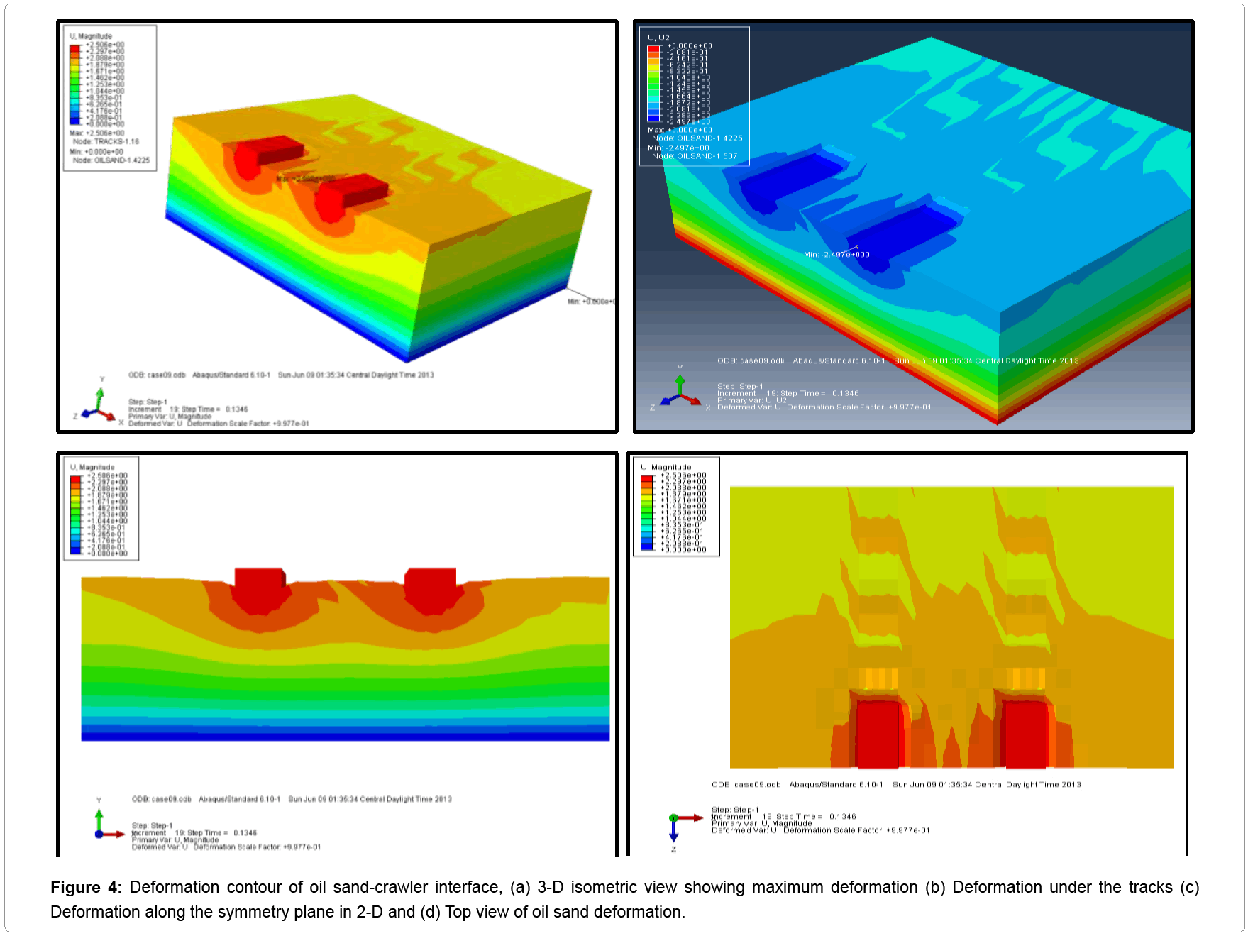
Oil sand deformation: Oil sand deformation occurred in a very short period of time (0.13 seconds) after crawler engagement. The maximum deformation of 2.497 cm in Figure 4 is indicative of the impact of shovel imposed gross weight on formation. The deformation contour shown in Figure 3a-3d is for single static loading. This implies that as the number of load cycles increases, the oil sand deformation will increase as well, which results in less stiffness and bigger rutting below the interface. The deformation results from the FE analysis is in close agreement with the real situation during crawler-ground interaction. It was observed, both in the field and laboratory testing, that a 1,350-tonne P&H 4100 BOSS cable shovel deformed an 11.8% bitumen content oil sand by 0.07 m on initial sitting and digging [6,7].
Oil sand failure pattern: The results show that the initial oil sand failure started below the track. The maximum plastic strains occurring at the edges of the tracks. This indicates why shovel failure starts in the form of cracking begins from the side of the undercarriage.
Results and Discussion
The results given below give the 3-D FE nonlinear behavior of oil sand-crawler interaction in terms of the variation of the stress, plastic strain, elastic strain and deformation. The oil sand is subjected to a static load given by the weight of P&H 4100XPC series cable shovel. Figures 4a-4d illustrate the3-D deformation results along the x-y plane of symmetry in a scale factor of 0.9977. The purpose of these figures is to illustrate the 3-D response of oil sands under static load. Figure 4a illustrates that deformation of the oil sand occurs underfoot the tracks and spreads laterally to the surface of the oil sand, the maximum deformation of 2.497 cm under the tracks at node 120. The tracks are shown to be undeformed because it was assumed to be a rigid member, and thus, sink into the oil sand formation. The deformation increases nonlinearly from the top surface to the bottom of the formation as shown in Figure 4c. Zones of deformation span into the footing/track distance as represented by (Figure 3c). The top view (Figure 3d) shows that deformation spreads in a concentric manner with maximum occurring at the edges of the track and beyond. These results enable easy identification of the oil sand failure zones. Vertical displacement of the oil sand below the track is shown in Figure 5 at a time of 0.13 seconds. This figure depicts a non-linear behavior of the formation under static loads.
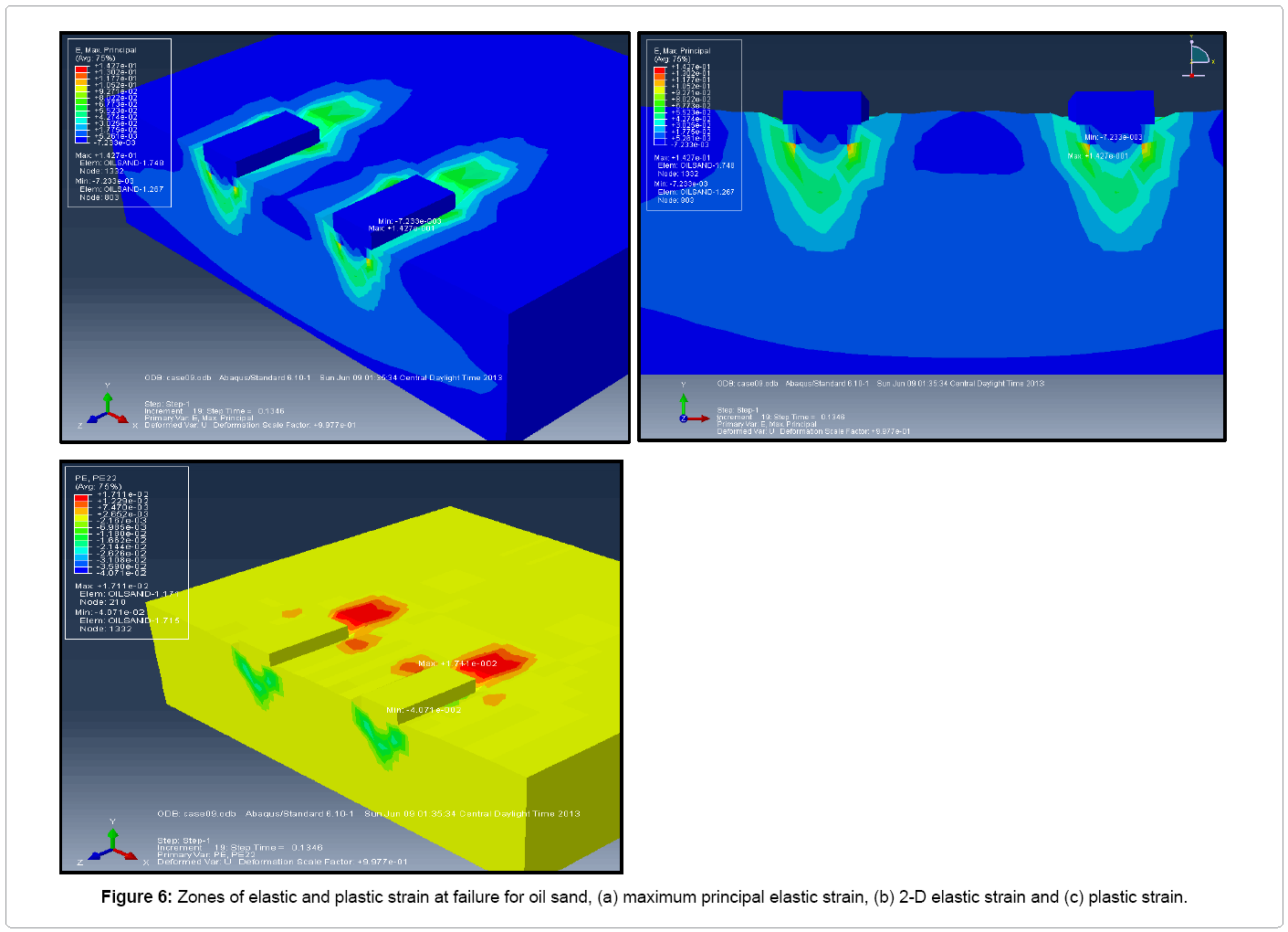
Figures 6a-6c presents elastic and plastic strains of the formation. Maximum elastic strain of 0.1427 occurs at node 1332 on the oil sand element as shown in Figure 6a. Figure 6b indicates the zone of plastic strain at failure for the oil sand in two-dimensional view along the symmetry plane. It shows that failure occurs mostly under the track at the edges and progresses nonlinearly to the bottom. The triangular failure pattern as seen below the tracks agrees well as reported in Terzaghi’s [1] early work on shallow foundation.
Conclusions and Recommendations
In this study, 3-D nonlinear FE model of oil sand-crawler interaction was created in ABAQUS [17] software to examine the behavior of the oil sand formation under static loads from the cable shovel. The FE model was developed based on the principle of soil mechanics by assuming that (i) the oil sand is homogeneous, isotropic undergoing elastic-plastic deformation; (ii) the crawler tracks were treated as a rigid strip footing resting on the oil sand; and (iii) the pressure distribution underfoot the tracks were uniform. The oil sand formation was modeled as elasticplastic material with strain-softening Mohr-Coulomb criterion. The results show that:
1. The maximum deformation range between 1.872 and 2.497 cm beneath the tracks indicating crack prone zone.
2. Displacement-time of the oil-sand track interface shows maximum value of -2.5 cm at 0.14 s.
3. The maximum elastic strain range between 9.271 x 10⁻² and -1.427 x 10⁻² and the minimum value is -7.233 x 10⁻³.
The following conclusions are made based on the FE simulation results from ABAQUS:
1. FE analysis has been implemented successful to fully produce 3-D oil sand-track interaction that reasonably predicts formation response to a static load.
2. Two distinct oil sand regions were observed from the plastic strain failure pattern: the region below the tracks recording larger strain at failure, the region adjacent the tracks expanding dipper and wider in all directions.
The FE model simulations provided the deformation and stress profiles of oil sand formation at the crawler-ground interface. The simulation model also provided the duration and failure surface conditions at the crawler-ground interface. The results also showed that the areas directly beneath the tracks had large deformations, due to the high pressure values. On the other hand, there was large transverse nodal displacement at the interface with large contact pressure. These areas are therefore prone to the high cyclic loads found in the field studies. This work was limited to crawler-ground interface under static loading from GMW of cable shovel. Future work will include a virtual prototype of cable shovel crawler-oil sand interaction to measure real-time stresses, crack initiation and propagation under dynamic conditions.
References
- Terzaghi K(1943) Theoretical soil mechanics, 4th ed., John Wiley and Sons, Inc. New York.
- Joseph TG(2002) OsEIP: The oil sands-equipment interactions program.CIM Bulletin 95: 58-60.
- Joseph TG, Hansen GW (2003) Oil sand reaction to cable shovel motion. CIM Bulletin95: 62-64.
- Joseph TG, Shi N (2013) Modeling Oil Sand Surface Response Below an in-pit Plant in the Canadian Oil Sands. CIM Journal4: 77-86.
- Anochie-Boateng J, Tutumluer E(2011) Sustainable use of oil sands for geotechnical construction and road building. Journal of ASTM International 9: 1-15.
- Sharif-abadi AD, Joseph TG (2010) An oil sand pseudo-elastic model for determining ground deformation under large mobile mining equipment. Geotech Geol Eng28: 471-481.
- Sharif-abadi AD, Joseph TG (2010) Oil sand deformation under cyclic loading of ultra-class mobile mining equipment. Journal of Terramechanics47: 75-85.
- Li Y, Frimpong S, Liu WY (2012) 3D finite element analysis of PWA-oil sand terrain system interaction. Advances in Acoustics and Vibration1-10.
- Girijavallabhan AM Reece LC (1968) Finite element method for problems in soil mechanics. Journal of the Soil Mechanics and Foundations Division29: 45-50.
- McCarthy DF (1988) Essentials of Soil Mechanics and Foundations, Basic Geotechnics, 3rd ed., Prentice Hall, Eaglewood Cliffs, NJ.
- Benmebarek S, Benmoussa S, Belounar L, Benmebarek N (2012) Bearing capacity of shallow foundation on two clay layers by numerical approach. Geotech Geol Eng30: 907-923.
- Griffiths DV (1982a) Computation of bearing capacity on layered soils. Proceedings 4th InternationalConference on Numerical Methods in Geomechanics1: 163-170.
- Burd HJ, Frydman S (1997) Bearing capacity of plane-strain footings on layered soils. CanGeotech J 34: 241-253.
- Zhu M (2004) Bearing capacity of strip footings on two-layer clay soil by finite element method.ABAQUS Users’ Conference 777-787.
- Liu X, Chan DH, Gerbrandt B9 (2008) Bearing capacity of soils for crawler cranes. Can Geotech J45: 1282-1302.
- Chiroux RC, Foster Jr. WA, Johnson CE, Shoop SA, Raper RL(2005) Three-dimensional finite element analysis of soil interaction with a rigid wheel. Applied Mathematics and Computation162: 707-722.
- Abaqus (2010) Analysis User’s Manual, Version 6.10, Dassault Systems Inc, Providence, RI.
- Samieh AM, Wong RCK (1997) Deformation of athabasca oil sand at low effective stresses under varying boundary conditions. Can Geotech J 34: 985-990.
- Li P(2005) Geomechanical model of oil sands SPE International Thermal Operations and Heavy Oil Symposium. Calgary, Alberta, Canada,SPE/PS-CIM/CHOA 97949, PS2005-430.
Relevant Topics
- Additive Manufacturing
- Coal Mining
- Colloid Chemistry
- Composite Materials Fabrication
- Compressive Strength
- Extractive Metallurgy
- Fracture Toughness
- Geological Materials
- Hydrometallurgy
- Industrial Engineering
- Materials Chemistry
- Materials Processing and Manufacturing
- Metal Casting Technology
- Metallic Materials
- Metallurgical Engineering
- Metallurgy
- Mineral Processing
- Nanomaterial
- Resource Extraction
- Rock Mechanics
- Surface Mining
Recommended Journals
Article Tools
Article Usage
- Total views: 16584
- [From(publication date):
October-2014 - Apr 09, 2025] - Breakdown by view type
- HTML page views : 11946
- PDF downloads : 4638

