Research Article Open Access
Analysis of Wellbore Pressure Drop on Horizontal Well Performance
Ohaegbulam MC*, Izuwa NC and Onwukwe SIDepartment of Petroleum Engineering, Federal University of Technology, Owerri, Imo State, Nigeria
- *Corresponding Author:
- Ohaebulam MC
Research Engineer at Petroleum Engineering Department FUTO
Department of Petroleum Engineering Federal University of Technology Owerri, Nigeria
Tel : + 23408066796449
E-mail: chukwudiohaegbulam43@gmail.com
Received Date: April 24, 2017; Accepted Date: May 11, 2017; Published Date: May 19, 2017
Citation: Ohaegbulam MC, Izuwa NC, Onwukwe SI (2017) Analysis of Wellbore Pressure Drop on Horizontal Well Performance. Oil Gas Res 3: 138. doi: 10.4172/2472-0518.1000138
Copyright: © 2017 Ohaegbulam MC, et al. This is an open-access article distributed under the terms of the Creative Commons Attribution License, which permits unrestricted use, distribution, and reproduction in any medium, provided the original author and source are credited.
Visit for more related articles at Oil & Gas Research
Abstract
The problem of wellbore pressure drop on horizontal well performance has been a concern to many researchers and the petroleum industry. Wellbore pressure losses in horizontal well not only increases gas or water conning tendency at the heel of the wellbore but also chokes oil production at the distant part of the wellbore especially for long horizontal wellbore thereby rendering some part of the horizontal well unproductive. This limits the usefulness of increasing the horizontal well length due to wellbore pressure losses along the horizontal well. A coupled reservoirwellbore model was developed in this work using Nodal analysis concept to investigate the performance of horizontal well by considering all the possible pressure losses in a horizontal well under inflow conditions. Sensitivity analysis of parameters that affect horizontal well productivity under wellbore pressure losses was performed. Results show that there exists an optimum horizontal well length beyond which oil production rate will no longer be proportional to horizontal well length and that wellbore pressure drop effects is severe in high productive reservoir with oil viscosity between 0.5 to 1cp or reservoir permeability of more than 200 md.
Keywords
Horizontal well performance; Reservoir inflow; Well deliverability; Nodal analysis; Optimum well length
Nomenclature
ΔPTh: Total pressure drop in the horizontal drain hole, Psi;
ΔPTt: Total pressure drop in the vertical tubing, Psi;
ΔPd: Reservoir draw down pressure, Psi;
ΔPf: Pressure drop due to friction, Psi;
Bo: Oil formation volume factor;
Ep: Error in productivity calculation for the drain hole;
Ep: Error in productivity calculation for both vertical tubing and the drain hole;
Js: Specific productive index, STB/day/Psi/ft;
J: Horizontal well productivity index, STB/day/Psi;
Kh: Horizontal permeability, md;
Kv: Vertical permeability, md;
LOpt: Optimum well length, ft;
NRe: Reynolds number;
Pe: External reservoir pressure, Psi;
Pwh: Well head pressure, Psi;
P (wf[x]): Varying bottom hole pressure, Psi;
Pwf: Constant bottom hole flowing pressure, Psi;
QOpt: Optimum flow rate, STB/day;
Qout: Actual inflow, STB/day;
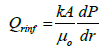
Qrinf: Reservoir inflow, STB/day;
fm: Fanning frictional factor;
gc: Conversion factor, 32.17lbm-ft/lbf-s2;
re: Drainage radius, ft;
rw: Wellbore radius, ft;
ε⁄d: Pipe relative roughness;
μo: Oil viscosity, cp;
A: Drainage area, ft2;
D: Wellbore diameter, inches;
h: Formation thickness, ft;
J: Productivity index, STB/day/Psi;
L: Horizontal well length, ft;
β: Reservoir anisotropy;
ε: Absolute roughness, ft;
ρ: Oil density, lbm/ft3.
Introduction
Horizontal well technology has become an important technique in oil and gas exploitation because of its ability to produce with a higher flow rate at a given reservoir pressure draw down [1]. Naturally, it was believed that horizontal well should be as long as possible; however recent research on horizontal wells has revealed that there is a factor that limits the useful length of horizontal well, that is in many circumstances the inflow performance of horizontal well does not match with the expected productivity and their deliverability maybe reduced by various pressure losses along the horizontal wellbore. This effect has serious implications where the horizontal well section is very long or reservoir productivity is high because beyond a certain well length productivity will no longer be proportional to the well length [2]. Most inflow equations Elegaghad [3-6] are based on the on the assumption that the wellbore flowing pressure is constant over the length of the horizontal well, implying that the wellbore pressure drop is negligible compared with other pressure drops in the system. Consequently the predictions of well performance and the reservoir drainage pattern may be erroneous. Numerous studies have examined the roles of wellbore pressure drop on the production performance of horizontal wells. Dikkens [7] was the first author to present analytical model to couple turbulent flow in the horizontal wellbore to the flow in the reservoir. He showed that in most practical situations, a horizontal well will exhibit turbulent flow and as such the infinite conductivity assumption should not be considered. He assumed a steady-state, single-phase pressure drop in the wellbore due to laminar or turbulent flow and linked the wellbore to the reservoir using a material balance relationships. He solved this problem analytically for an infinite length horizontal well and numerically for a finite length horizontal well. He concluded that beyond a certain well length, frictional losses would result in constant oil production as the well length increases. One of the shortcomings Erdal et al. [8] of Dikkens analytical model is that it cannot incorporate any frictional factor correlation. Novy [9] generalized Dikken work by developing an equation for both single-phase oil and single-phase gas flow. The problem was formulated as a boundary value problem and was solved using a finite difference scheme. He showed that wellbore pressure due to frictional effects reduce production rate by at least 10% when the wellbore pressure drop is more than 15% of the draw down at the heel of well. He concluded that if the ratios of wellbore pressure to the reservoir draw down at the heel is greater than 10%, then friction losses will significantly reduce oil production rate. Alfred and Ding [10] presented a simple analytic equation that can be used to determine the relative effects of wellbore pressure drop on horizontal well performance. The equation assumed a steady-state flow in the reservoir and wellbore respectively. Cho and Subhash [11] investigated the effects of reservoir and well parameters on horizontal well productivity using Dikkens model. One of their main conclusions was that oil production rate will be significantly overestimated if frictional losses in the wellbore is neglected in long horizontal well and that the determination of optimum horizontal well length will save the cost of drilling and completion of section that maybe unproductive due to frictional losses.. Penmatcha et al. [12] presented a semi analytical equation that coupled the wellbore model to the reservoir model with the view of investigating the horizontal well performance under frictional losses. They defined a parameter Ep which is the error in productivity calculation when friction is neglected as the ratio of the wellbore pressure drop to the reservoir draw down pressure at the heel. They stated that error in productivity calculation increases with the well length, permeability and decreases with increase in wellbore diameter and that the effects of wellbore friction on horizontal well results to none uniform flow along the well length; consequently early water or gas breakthrough at the heel of the wellbore. They pointed that because of frictional effects, incremental recovery of oil decreases with increasing well length but the drilling and completion costs increases almost linearly as the well length. They concluded that because of this, there will be a certain well length that maximizes revenue. Orodu and Fadiaro [13] defined optimum horizontal well length similar to that of Penmatcha stated the length that gives maximum net present value by putting into consideration the wellbore frictional effect. They calculated the initial oil production rate without frictional effects using Renard and Dupuy [14] model, and then substitute their values in Dikkens [7] model to calculate the production rate with friction. They concluded that the net present value serves as the objective function to maximize the horizontal well length.
Model Formulation
To investigate the effects of wellbore pressure drop on horizontal well performance, some system of equations that govern the behavior of this physical process must be postulated. The basic equation is obtained by combining two physical principles, namely:
• Energy equation
• Rate equation
The energy equation
The theoretical basis of many fluid flow equations is the general energy equation, an expression for balance or conservation of energy between two points in a system. The energy equation simply states that the energy of a fluid entering a control volume, plus any shaft work done on or by the fluid, plus any heat energy added to or taken from the fluid, plus any change of energy with time in a control volume must be equal to the energy leaving the control volume (Beggs, 1991). The energy equation maybe written in its differential form as:
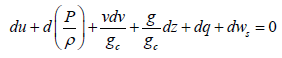 (1)
(1)
Eqn. (1) can be re-written in its final form as:
 (2)
(2)
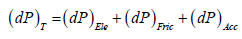
Eqn. (2) is transformed in field unit with their various components to account for the total wellbore pressure drop:
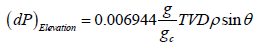 (3)
(3)
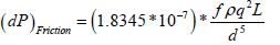 (4)
(4)
 (5)
(5)
Eqn. (4) is a function of the friction factor which is a function of Reynolds number. Reynolds number as defined by Osorborn Reynolds (1984) can be written in field unit as:
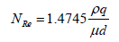 (6)
(6)
For laminar flow [NRe< 2100] , Fanning frictional factor is defined as:
 (7)
(7)
Many correlations are available in the literature to calculate the friction factor for turbulent flow (James and Mukherjee, 1989). However, in this work Jain [15] explicit equation is used which is given as:
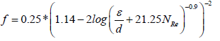 (8)
(8)
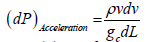
Eqn. (2) through eqn. (8) is the wellbore model comprising of the pressure drop due to elevation, acceleration and friction. Where (dP)T is the total pressure drop in Psi, TVD is the true vertical depth in ft, ρ is the oil density in flow rate in
 fluid velocity in
  , L well length in ft, g and gc are acceleration constant
  wellbore diameter in inches, and μ fluid viscosity in cp. It is pertinent to note that for a constant area slightly compressible steady-state flow, the effect of acceleration is negligible and is generally neglected while for compressible fluid, acceleration effect is not negligible, hence cannot be neglected [16,17].
Rate equation
The fundamental law of fluid motion in porous media is Darcy’s law which states that the velocity of a homogenous fluid in porous medium is proportional to the pressure gradient and inversely proportional to the fluid viscosity:
 (9)
(9)
 (10)
(10)
Eqn. (10) can be transformed to productivity index per unit length:
 (11)
(11)
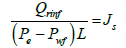
Where Js, is the productivity index per unit length of the wellbore and can be expressed as:
 (11A)
(11A)
J is the horizontal well productivity index which depends on the reservoir properties, well parameters and the geometry of the system. The various forms of horizontal well productivity index under steadystate flow have been extensively reviewed in the literature. Joshi (1989) productivity index equation is used in this study.
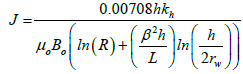 (12)
(12)
Eqn. (11) through eqn. (12) is the reservoir flow model which describes flow in the reservoir or porous media. Eqns. (2) and (12) will be coupled to obtain a model that describes horizontal well performance under wellbore pressure losses.
Coupling of the wellbore model to the reservoir model
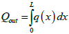
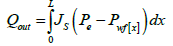
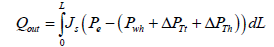
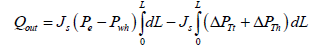
Figure 1 shows a horizontal well in a reservoir. Let Pe be the pressure at the outer boundary of the reservoir and P(wf[x]) be the varying wellbore pressure along the wellbore due to wellbore pressure drop. The outflow equation is given as:
 (13)
(13)
 (14)
(14)
 (15)
(15)
Where  is the varying bottom hole pressure as a result of wellbore pressure drop. The coupling concept can be categorized in two cases:
• Case 1: only the drain hole is considered, Node 2-3. From Figure 1, at node 2 out flow pressure:

Figure 1: Schematic diagram of flowing Horizontal well.
 (16)
(16)
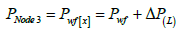
At node 3, out flow pressure:
 (17)
(17)
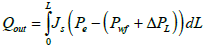
Substituting eqn. (17) into eqn. (15) and integrating:
 (18)
(18)
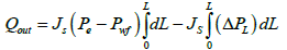 (19)
(19)
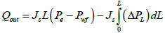 (20)
(20)
At the inner boundary, L=0 (heel), eqn. (20) becomes:
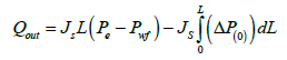 (21)
(21)
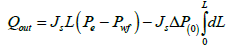 (22)
(22)
 (23)
(23)
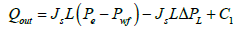
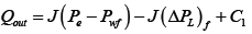 (24)
(24)
Recall in eqn. (11):
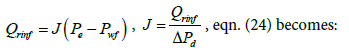
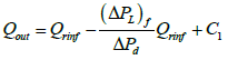 (25)
(25)
At the heel, 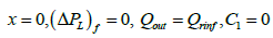 eqn. (25) becomes:
 (26)
(26)
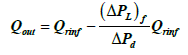
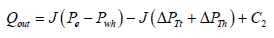
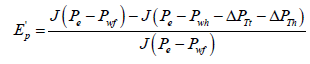
Eqn. (26) is the reservoir-wellbore model, where (ΔPL)f is the pressure drop in the horizontal drain hole which is composed of friction effects only, ΔPd is the reservoir draw down pressure, Qrinf and Qout are the reservoir inflow and wellbore out flow with friction effects respectively. Eqn. (26) can be re-arranged to calculate the error in productivity when friction effect is neglected:
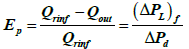 (27)
(27)
• Case 2: both the drain hole and the vertical section of the horizontal well are considered, node 1-3. From Figure 1 at node 1, out flow pressure:
 (28)
(28)
At node 2, out flow pressure:
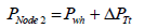 (29)
(29)
At node 3, out flow pressure:
 (30)
(30)
Substituting eqn. (30) in eqn. (15) and integrating:
 (31)
(31)
 (32)
(32)
 (33)
(33)
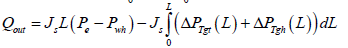
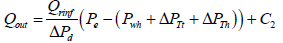
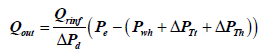
Where ΔPTgt and ΔPTgh are the total pressure gradient at the vertical tubing and horizontal section of the horizontal well respectively. Integrating the above equation with respect to L:
 (34)
(34)
 (35)
(35)
 (36)
(36)
 (37)
(37)
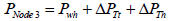
At the heel,  , eqn. (37) becomes:
 (38)
(38)
Where Pwh is the well head pressure, ΔPTt and ΔPTh are the total pressure drop at the vertical tubing and horizontal drain hole respectively. The total pressure drop at the vertical tubing is composed of the pressure drop due to elevation and friction, while the total pressure at the horizontal hole is composed of pressure drop due to friction only. The acceleration effect is neglected in this work because it is assumed that the fluid is slightly compressible flowing in a uniform area wellbore. Error in productivity can be calculated by combining both eqns. (11) and (38):
 (39)
(39)
 (40)
(40)
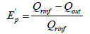
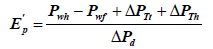 (41)
(41)
Ep’ is the error in productivity calculation when the pressure drops in the vertical and horizontal section of the horizontal well are neglected.
Computational Procedure
The data provided in Table 1 were used to calculate the productivity of horizontal well considering wellbore pressure drop using the proposed models. The following are the computational steps:
| Pe:4000Psi | Drainage area:120acre |
| μo=0.5-10 cp | Thickness, h: 20-350ft |
| Steel type: well tubing | kh : 50-120md |
| Well diameter=2-10” | Pwf:3975 |
| L: 5000-8500ft | Anisotropy,β:0.5-10 |
| Density:52.4lbm/ft3 | ε:c0.00005-0.00075 |
| FVF, Bo:1.18rb/STB | API:32°-42° |
| Skin factor=0 | TVD: 6500ft |
| Pwh=1607.5Psi | θ=90° |
Table 1: Reservoir conditions and well parameters.
1. Calculate oil production rate without wellbore pressure drop using any infinite conductive model or Joshi model.
2. Calculate the wellbore pressure drop using eqn. (2) through eqn. (8)
3. Calculate the actual flow rate or out flow using eqn. (26) or eqn. (38)
4. Repeat step one through step three for different well lengths and plot the graph of step three against well length.
Results and Discussion
Figure 2 shows the comparison between the proposed model (finite conductive model) and Joshi model (infinite conductive model). It can be seen from the graphs that Joshi model exhibits an infinite productivity with well length; while for the proposed model productivity increases with well length until optimum length is reached beyond which the well length will no longer be proportional to oil production rate due to wellbore pressure drop effects. Figures 3-6 shows the results of the sensitivity analysis of reservoir and well parameters on horizontal well performance under wellbore pressure losses using the proposed model. It can be adduced from the graphs that in most cases oil production rates are no longer proportional to the well length beyond the optimum well length and that longer horizontal well length is required to reach maximum oil production rate for the cases of low productivity reservoir than high productivity reservoir. This can be seen from the longer optimum length from the graphs of high oil viscosity, low permeability, small wellbore diameter etc. This means that the effects of wellbore pressure on horizontal well productivity depend on reservoir, fluid and well parameters. In the case of very high productivity reservoir (Kh>300 md), drain holes or multilateral well is a better exploitative option than horizontal well. Figures 7-9, show the relationship between the wellbore pressure drop and horizontal well length for different values of reservoir properties and well parameters. Wellbore pressure drop increases with well length in all cases, while at a fixed well length wellbore pressure increases with decrease in oil viscosity, wellbore diameter and increase in reservoir permeability etc. This depicts that wellbore pressure drop is significant in high productive reservoir and well with small wellbore diameter restriction. Figure 10 shows the coning tendency of water or gas at the heel of the horizontal well due to wellbore pressure drop. It can be observed that for an infinite conductive model (Joshi model), the bottom hole flowing pressure is constant along the entire well length; while for a finite conductive model (proposed model), the flowing bottom hole pressure increases from the heel to the toe of the wellbore. Consequently, oil production rate increases from the toe to the heel resulting to non-uniform flow along the well length. The higher oil production rate at the producing end of the wellbore (heel) due to higher pressure draw down enhances water/gas breakthrough tendency at the heel. Conversely, at the toe of the wellbore additional pressure is imposed by wellbore/friction effects, resulting to low oil production rate and delay in water/gas breakthrough at the toe of the wellbore. Figure 10 also shows that the effect of wellbore pressure drop is significant when it is comparable to the reservoir draw down pressure.

Figure 2: Comparison of infinite and finite conductive Model.

Figure 3: Effects of Reservoir permeability on horizontal well productivity.

Figure 4: Effect of Oil Viscosity on Horizontal well.

Figure 5: Effects of Reservoir drawdown Pressure on horizontal well productivity.

Figure 6: Effects of well bore diameter on horizontal well productivity.

Figure 7: Relationship between wellbore pressure drop and reservoir permeability.

Figure 8: Relationship between Oil Viscosity and wellbore Pressure drop.

Figure 9: Relationship between Reservoir drawdown pressure and wellbore Pressure drop.

Figure 10: Breaking through Tendency at the heel of the well bore.
Conclusions
This research work was concerned with the effects of wellbore pressure drop on horizontal well performance. A reservoir-wellbore model was developed and a sensitivity study of various parameters that affects productivity under wellbore pressure losses was performed. The following conclusions are hereby presented:
• A coupled reservoir-wellbore model is presented to account for wellbore pressure losses in horizontal well.
• There exists an optimum horizontal well length beyond which oil production rate will no longer be proportional to well length.
• Determination of optimum horizontal well length during horizontal well construction will maximize profit and minimize costs.
• Wellbore pressure drop can lead to early water/gas breakthrough at the heel of the horizontal wellbore.
• Wellbore pressure losses are severe in highly productive reservoir and for reservoir where oil flow is restricted to small tubing diameter.
References
- Joshi SD (1987) A review of horizontal and drain hole technology. SPE paper 16868 presented at the 6th Annular Conference and Exhibition of Society of Petroleum Engineers, Dallas.
- Joshi SD (1991) Horizontal well technology Tulsa OK Penn well Publishing Company
- Elegaghad SA, Osisanya SO, Tibia (1996) A simple productivity equation for horizontal well based on drainage area concept. SPE paper 35113 Presented at the Western Regional Meeting Anchorage Alaska.
- Guo B, Xiance Y, Mohammad K (2009) A simple analytical model for predicting productivity of multi fractured horizontal wells. Journal Petroleum of Technology.
- Joshi SD (1988) Augmentation of well productivity using slant and horizontal wells. Journal Petroleum Technology.
- Lu J (2001) New Productive formula of horizontal wells. Journal of Canadian Petroleum Technology PET, Vol. 40.
- Dikkens BJ (1990) Pressure drop in horizontal wells and its effects on production performance. Journal of Petroleum Technology, Vol. 42.
- Erdal O, Cem S, Marc H (1999) Influence of pressure drop along the wellbore on horizontal well productivity, Journal of Petroleum Technology JPT, Vol. 4.
- Novy RA (1995) Pressure drops in horizontal wells when can they be ignored.? Journal Petroleum Technology, Vol. 10.
- Alfred DH, Ding Z (2008)The relative importance of wellbore pressure drop and formation damage in horizontal wells. Journal of Petroleum Technology, Vol. 23.
- Cho H, Shah SN (2001) Prediction of specific productivity index for long horizontal wells. SPE Paper 27237 presented at SPE, International Petroleum Conference Oklahoma.
- Penmatcha VR, Arbabi S, Aziz K (1999) Effects of pressure drop in horizontal well and optimum well length. Journal of Petroleum Technology.
- Orodu OD, Fadairo AAS, Enebele EE (2012) Realistic optimization of well length for horizontal drilling. Brazilian Journal of Petroleum and Gas
- Renard GI, Dupuy JM (1991) Formation damage influence on horizontal well flow efficiency. Journal Petroleum Technology, Vol. 43
- Jain AK (1976) Accurate explicit equation for frictional factor. J Hydraulic Division102: 674-677.
- Ankalm EG, Wiggins ML (2005) Horizontal well productivity and wellbore pressure behavior incorporating wellbore hydraulics. Paper SPE 94316 presented at the SPE Production Operation Symposium Oklahoma City.
- James P, Hemante M (1998) Multiphase flow in pipes Society of Petroleum Engineers. Inc Richardson Texas, pp: 5-7.
Relevant Topics
Recommended Journals
- Oil & Gas Research Journal
- Renewable Energy and Applications Journal
- Oceanography Journal
- Industrial Pollution Control Journal
- Coastal Zone Management Journal
- Climatology & Weather Forecasting Journal
- Geoinformatics & Geostatistics Journal
- Engineering and Technology Journal
- Petroleum & Environmental Biotechnology Journal
- Polymer Sciences Journal
Article Tools
Article Usage
- Total views: 9008
- [From(publication date):
August-2017 - Mar 31, 2025] - Breakdown by view type
- HTML page views : 7805
- PDF downloads : 1203