Analysis of Various Methodologies for Solar Power Generation: Applicable to Meet the Energy Demand of Developing Country like India
Received: 29-Oct-2016 / Accepted Date: 23-Nov-2016 / Published Date: 26-Nov-2016
Abstract
India’s National Solar Power capacity has been set targeted to 100 GW by the year 2022. The recent approvals to ramp up the India’s Solar Power capacity by five times the previous target has been split into 40 GW of Rooftop and 60 GW of large and medium scale grid connected solar power projects. This injects inquisitiveness about the current technologies available to meet the target, as well as the feasibility study to be made to check whether the target of 40 GW roof top will be satisfied by the Photovoltaic only or some other technologies like Rankine cycle steam turbine generators or Stirling engine should be scaled down to small capacity, since the photovoltaic available in the market is having an average efficiency of 18%. Hence bifurcations of the requirement have to be made to achieve the target with more overall solar to electrical efficiency. And, the effort made here is to show that the target can be achieved with the same or less amount of cost and space which are the major concern nowadays.
Keywords: Solar insolation; Ellipse; Photovoltaic cell; Stirling cycle
19177Introduction
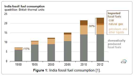
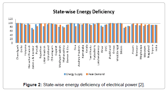
India’s dependence on Fossil fuel rose to 38% in 2012, despite the country having significant domestic fossil fuel resources. Also India ranked as the fourth-largest energy consumer in the world in 2011, following China, the United States, and Russia [1]. In 2013, India was the fourth-largest consumer and net importer of crude oil and petroleum products in the world after the United States, China, and Japan. As mentioned by Power ministry of India Electricity generation target of India during this financial year is set to be 1137.5 Billion Units of which 69.6% is from conventional fuels mainly Coal, gas and oil (Figures 1 and 2) [2].
Figure 1: India fossil fuel consumption [1].
Figure 2: State-wise energy deficiency of electrical power [2].
Above figure shows the State-wise energy deficiency as well as overall energy deficiency in India as per the data obtained [3].
SUN, the ultimate source of energy is responsible for fulfilling the major requirements of all living creatures on earth. This energy is incident in the form of electromagnetic waves or photons (theorized by Albert Einstein). But all the photons are not of the same energy. The variation of the energy of photons is a function of its wavelength. The total energy radiated by sun approximately equals to the energy radiated by a black body of temperature 5776 K [4]. This energy is called the Solar constant outside the earth’s atmosphere. The typical value of solar constant is 1366 W/sq. meter with measurement uncertainty of ± 3 W/sq. meter [4]. The value of solar constant is not constant; in fact, it varies in relation with solar activities like sunspots. Also sun rotates about its own axis in about 27 days and thus the variation of the value of solar constant is about 0.1%, which has quite negligible effect.
The solar energy incident on the earth’s surface passing through the atmosphere is called Solar Insolation and is given by the formula [4]:
 (1)
(1)
 (2)
(2)
Where,
S is the solar constant;
(dm/d)is the ratio of mean to actual distance of earth from sun;
λ is the latitude angle;
δ is the declination angle;
h is the hour angle of sun.
In addition, the energy that is falling on the surface of the earth is different in case of Northern hemisphere and southern hemisphere. Because of the earth’s orbital being ellipse [5] in shape the phenomenon called perihelion and aphelion occurs. Due to this phenomenon, the energy falling on the earth’s surface during winter season in the southern hemisphere is 93.55% less than the northern hemisphere [6].
Earth’s Solar Resource
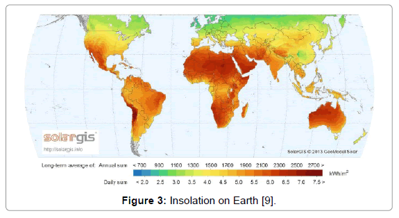
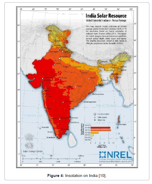
Below mentioned figure shows the Global horizontal Irradiance falling on the Earth’s surface. India’s map depicts that several states in India are suitable for harnessing this solar energy blessed by the sun. According to Trans-Mediterranean Renewable Energy Corporation (TREC), each square kilometer of hot desert receives solar energy equivalent to 1.5 barrels of oil [7]. The Thar Desert of India receives energy sufficient to generate 700-2100 Giga Watts (GW) of energy [8].
To harness this energy, different kinds of technologies have been developed over the past few years, which can be classified as Solar Photovoltaic and Solar Thermal (Figures 3 and 4) [9].
Figure 3: Insolation on Earth [9].
Figure 4: Insolation on India [10].
Solar photovoltaic cell
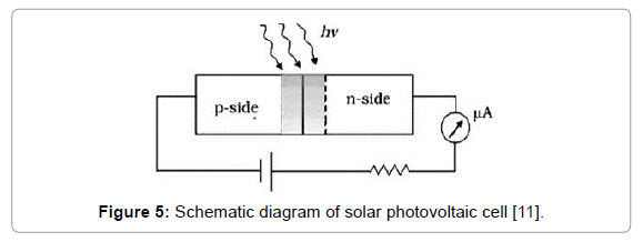
The technology which converts directly solar energy into electrical energy. When radiation falls on a photovoltaic cell it absorbs the light depending on the band gap of the cell, this absorbed photon creates electron hole pair which flows into the external circuit and hence generates the electric current.
The amount of electrical energy generated depends on internal quantum efficiency and external quantum efficiency. The first efficiency is the conversion of incident photons into the no. of electron hole pair while the second efficiency is indicating how much no. of electrons exited from the semiconductor after being generated. The overall efficiency of the photovoltaic cell varies widely depending on the type (Figure 5) [10-12].
Figure 5: Schematic diagram of solar photovoltaic cell [11].
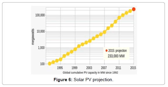
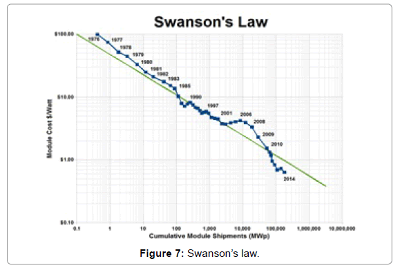
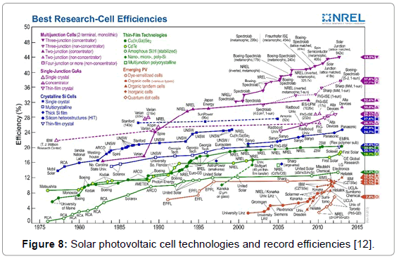
Advancement in Solar photovoltaic is related to the development of new materials as well as combining different material for increasing the absorptivity of the cell and hence increasing the absorption of number of photons which are incident on the cell. Solar photovoltaic technology is 160 years old. The first experimentation with the metal electrode and electrolyte was done by French physicist Alexander Edmond Becquerel in 1839. After the photoelectric effect got discovered by Albert Einstein in 1905, first high power silicon solar cell was developed by Bell Labs in 1954 and which turned to be a paradigm shift in the renewable energy field. From cell to module, module to array and so on the production of silicon solar cell increased as predicted by the Moore’s law. The cost also reduced following the Swanson’s law (Figures 6-8).
Figure 8: Solar photovoltaic cell technologies and record efficiencies [12].
Below mentioned figure shows the types of photovoltaic cells and its corresponding highest efficiency recorded.
There are two types of system configuration for solar photovoltaic namely Grid tied and Stand Alone photovoltaic system, each one of them having its own pros and cons as well as applications [12-14].
Grid tied photovoltaic system
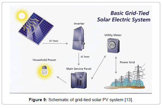
Grid Tied Solar photovoltaic system is similar to any power generating plant which is connected to the grid for transmitting power. When light falls on the solar panel, DC power is generated. This is feed to inverter which converts this DC to AC power which will be matching phase, frequency and voltage as that of grid. A grid tied system is always accompanied by an electrical meter having net metering facility. Hence, the total power generated will be the difference between the power generated and the power used by the utility and other facility which is necessary for the operation of the plant (Figure 9).
Figure 9: Schematic of grid-tied solar PV system [13].
Advantage of Grid connected Photovoltaic system is that it gives an opportunity to introduce large amount of power at a time but the plant load factor or capacity factor is not more than 17-21% [15].
Stand-alone photovoltaic system
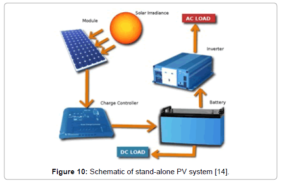
Off-grid or Stand-alone photovoltaic system includes the storage of the power that is generated when the demand is less than what is generated. A component called charge controller is introduced in the system which is managing the charging process of the battery by regulating the electric current that is being generated by the solar panels. The working of the charge controller is divided in three modes: First is when the power generated is completely utilized by the AC load, the charge controller does not charge the battery and supplies direct power to the inverter which is then consumed by the loads. Second is when the AC load and DC load is working simultaneously, charge controller will charge the battery and from there the current is fed to the load. Third is during night time or no sunlight condition the charged battery is being consumed up to its set low voltage value (Figure 10).
Figure 10: Schematic of stand-alone PV system [14].
Generally renewable energy always has an impression that it can be provide power intermittent and in specific duration only but because of the introduction of storage option the plant load factor or capacity factor can be increased. At the same time, the economic feasibility needs to be taken care of as one the researcher suggested that $0.35- 0.63 per Watt PV for the 80 MW plant and $0.56-0.94 per Watt PV for the 5 MW plant is added by inserting energy storage unit [16].
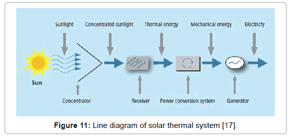
Another way to use solar energy and convert it to electricity is by using concentrated solar power technologies. The principle of concentrated solar thermal is mentioned in the Figure 11. One of the major differences between solar thermal and conventional thermal power plant is the fuel used. Here there is no fossil fuel used to generate steam and hence it creates no greenhouse gas emission. It is different than photovoltaic in terms of the input that can be provided to generate steam. Photovoltaic panel work on the Global Horizontal Irradiance (GHI) while solar thermal or CSP technology needs Direct Normal Irradiance (DNI). As per one report it is suggested that the ideal place for CSP technology to work is between 40° north and south of equator [17,18] which includes Middle East, North Africa, South Africa, India, southwest United States, Mexico, Peru, Chile, Western China, Australia, southern Europe and Turkey [19].
Figure 11: Line diagram of solar thermal system [17].
There are many technologies available to convert solar radiation into heat and finally to electricity using different energy conversion system. The technologies which convert solar to heat are parabolic trough, Linear Fresnel, Heliostat tower and Dish Stirling engine.
Parabolic trough technology
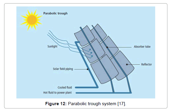
It consist of a curved, mirrored trough which reflects the direct solar radiation onto a glass tube containing a fluid which is heat transfer medium running through the trough length, positioned at the focal line of the reflectors. Single axis or daily tracking is introduced in this technology so that the heat transfer fluid is continuously heated up during the day-length. The temperature can rise up to 400°C. Hot liquid is passed through a series of heat exchangers to generate steam and drive a turbine. Parabolic trough is the most prevalent and proven technology amongst CSP technologies. According to Dr Yehuda Harats of EnerT International Ltd., “Parabolic trough is less sensitive to variations and fluctuations in DNI than any other CSP technology” (Table 1 and Figure 12) [12,20].
| Country | Operational | Under Construction | Planning | |||
|---|---|---|---|---|---|---|
| Number of Plants | Total Capacity (MW) | Number of Plants | Total Capacity (MW) | Number of Plants | Total Capacity (MW) | |
| Algeria | - | - | 1 | 25 | 3 | 215 |
| Australia | - | - | - | - | 2 | 350 |
| China | - | - | - | - | 5 | 281 |
| Egypt | - | 1 | 40 | 2 | 100 | |
| India | - | - | 1 | 10 | 11 | 590 |
| Iran | - | - | - | - | 1 | 67 |
| Israel | - | - | - | - | 2 | 440 |
| Italy | - | - | 1 | 5 | - | - |
| Mexico | - | - | 1 | 12 | - | - |
| Morocco | - | - | 1 | 30 | 3 | 275 |
| S0.2pain | 14 | 700 | 16 | 800 | 16 | 772 |
| Tunisia | - | - | - | - | 2 | 200 |
| UAE | - | - | 1 | 100 | - | - |
| USA | 14 | 468 | 2 | 355 | 43 | 20377 |
| Total | 28 | 1168 | 25 | 1377 | 90 | 23667 |
Table 1: Status of parabolic trough systems over the world [21].
Figure 12: Parabolic trough system [17].
Parabolic trough is proven technology with more than 1000 MW capacity of installation accompanied by a well-established supply chain. Majority of the plants are having a facility of thermal storage which is very important for increasing the plant load factor. Also it permits ease of hybridization with fossil fuels. But when it comes to overall efficiency of the system, the limitation in temperature of the heat transfer fluid up to 400°C makes it disadvantageous. System is still containing complex ball joints and flexible Piping from which there is a chance of leakage of heat transfer fluid. There is also geometrical requirement of a near flat land for installation of parabolic trough over the field.
Central receiver tower
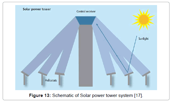
Central receiver tower is formed by a field of heliostat which is plane mirror spread over a large area such that they reflect the radiation at a central receiver where a heat transfer medium or heat storage medium is circulated. This medium achieves a temperature of 600°C. This fluid is again used to generate steam which rotates the turbine and hence generates power. Literature suggests those solar power towers are having high conversion efficiency than parabolic trough (Figure 13) [20].
Figure 13: Schematic of Solar power tower system [17].
The status of plants around the world is shown in Table 2. High temperature storage fluids like molten salts can be used in the system which can go up to 600°C which was not in case of parabolic trough and hence increases efficiency of the system. The mirrors are flat in shape as well as land slope is acceptable up to 5°. On the other hand because of point focus requirement, two-axes tracking with precision control are must. In addition, a large number of heliostats are required but still during summer when sun is exactly at the top, performance of the plant is degraded.
| Country | Operational | Under Construction | Planning | |||
|---|---|---|---|---|---|---|
| Number of Plants | Total Capacity (MW) | Number of Plants | Total Capacity (MW) | Number of Plants | Total Capacity (MW) | |
| Australia | 1 | 0.5 | 1 | 3 | 1 | 4 |
| China | - | - | 3 | 52 | 1 | 100 |
| France | - | - | 1 | 1.4 | - | - |
| Germany | 1 | 1.5 | - | - | - | - |
| India | 1 | 2.5 | 1 | 7.5 | - | - |
| RSA | - | - | 1 | 50 | 1 | 100 |
| Spain | 3 | 50.9 | - | - | - | - |
| USA | 1 | 5 | 5 | 897 | 14 | 5583 |
| Total | 7 | 60.4 | 13 | 1010.9 | 17 | 5787 |
Table 2: Status of solar power tower installation over the word [21].
Linear Fresnel technology
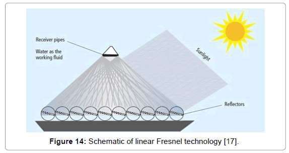
The technology similar to power tower consist of long flat reflectors which are reflecting radiation on one or more pipes containing heat transfer medium which has the same working as previous technologies. The main advantage of this technology is cost and space utilization being minimum; while the thermal storage technology for linear Fresnel is still under development (Figure 14).
Figure 14: Schematic of linear Fresnel technology [17].
The status of plants around the world is shown below: The major attraction of this technology is its low cost of components and lower consumption of land as compared to previous technologies (Table 3). It also gives the opportunity to indigenize the components but low cost backlashes with the optical efficiency and large thermal storage.
| Country | Operational | Under Construction | Planning | |||
|---|---|---|---|---|---|---|
| Number of Plants | Total Capacity (MW) | Number of Plants | Total Capacity (MW) | Number of Plants | Total Capacity (MW) | |
| Australia | 2 | 4* | - | - | 3 | 423 |
| China | - | - | 1 | 2.5 | - | - |
| France | 1 | 0.25 | 1 | 12 | - | - |
| Jordan | - | - | - | - | 1 | 100 |
| India | - | - | 2 | 250 | - | - |
| Portugal | - | - | - | - | 2 | 13 |
| Spain | 2 | 31.4 | - | - | - | - |
| USA | 1 | 5 | - | - | - | - |
| Total | 6 | 40.65 | 4 | 264.5 | 6 | 536 |
Table 3: Status of linear fresnel system installation over the world [21].
Solar dish systems
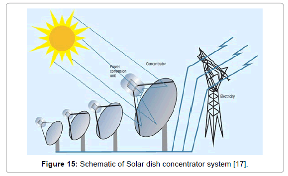
It comprises a dish-shaped concentrator (like a satellite dish) that reflects solar radiation onto a receiver mounted at the focal point. The receiver is a Stirling engine coupled with a generator. Dish systems are said to be more suitable for standalone, small power systems due to their modularity. However, such small power dishes can be installed in DNI rich area to obtain enough generation.
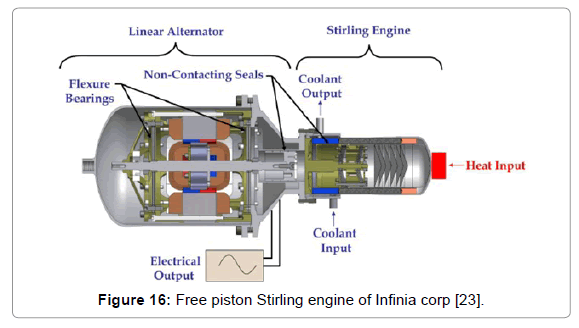
CSP technologies use combinations of mirrored concentrators to focus the solar radiation to receivers that convert the energy into high temperature for power generation. The status of this technology in world and in India (Figure 15). Table 4 shows the plants of Parabolic Dish Stirling Engine under Operation, Construction and Planning phases. The latest technology used for producing direct solar to electricity without producing steam or transferring the heat to any other forms of energy other than mechanical energy is by using free piston Stirling engine. The technology is demonstrated by Infinia Corp power dish which has a range of capacity varying from 3 kWe to 25 kWe having size of diameter of dish 5 meter and 15 meter respectively (Table 5 and Figure 16) [20,21].
| Country | Operational | Under Construction | Planning | |||
|---|---|---|---|---|---|---|
| Number of Plants | Total Capacity (MW) | Number of Plants | Total Capacity (MW) | Number of Plants | Total Capacity (MW) | |
| Australia | - | - | - | - | 1 | 40 |
| France | - | - | - | - | 1 | 50 |
| India | - | - | - | - | 1 | 10 |
| Spain | 1 | 0.01 | 1 | 1 | 3 | 59 |
| USA | 1 | 1.5 | - | - | 8 | 3095 |
| Total | 2 | 1.51 | 1 | 1 | 14 | 3254 |
Table 4: Status of solar dish stirling systems installed over the world [21].
| Name | Type | Aperture(m) | Dia(m) | Focal length (m) | Concentration Ratio | Receiver dia(m) | Engine | HTF | Working Temperature(C) | Promoter | Design Power(kW) | Max. Efficiency | Year | m2/kW |
|---|---|---|---|---|---|---|---|---|---|---|---|---|---|---|
| Sun dish | Stretched membrane | 113 | 15 | 12 | 1558 | 0.4 | STM 4-120 | H2 | 720 | SAIC | 22 | 0.23 | 1999 | 5.14 |
| Sun catcher | Parabola with facet | 88 | 11 | 7.45 | 2756 | 0.2 | 4-95 kockums | H2 | 720 | SAIC | 25 | 0.23 | 1999 | 3.5 |
| WGA | Parabola | 41 | 8.8 | 5.45 | 2145 | 0.2 | V161 Solo | H2 or He | 650 | WGA | 11 or 8 | 0.24 | 1999 | 3.73-5.13 |
| Euro dish | Parabola | 57 | 8.5 | 5.45 | 2001 | 0.2 | V161 Solo | H2 or He | 650 | SBP | 11 | 0.23 | 2001 | 5.18 |
| AZ-TH | Parabola with facet | 56 | 5 | - | 0.2 | V161 Solo | H2 or He | 650 | Abengoa | 11 | 0.23 | 2007 | 5.09 | |
| Power dish | Parabola | 14.7 | 4.2 | - | - | - | Infinia | He | - | Infinia | 3 | 0.24 | 2007 | 4.9 |
| Sun machine | Parabola | 15-17 | 4-5 | - | - | - | Sun machine | N2 | - | Sun machine | 3 | 0.2-0.25 | 2007 | 5-5.6 |
Table 5: Status of Stirling engine systems developed over the world.
Figure 15: Schematic of Solar dish concentrator system [17].
Figure 16: Free piston Stirling engine of Infinia corp [23].
Other than Infinia some more developers have been promoting this technology. A list of them is shown below:
It is clear from the above table that as compared to a photovoltaic plant which requires a minimum 10 m2/kW, here the mirror area is lower to a value 3.5 m2/kW. This signifies a great potential in this technology. Also not only the area but also the maximum efficiency is slightly on higher side as compared to photovoltaic system.
The major advantage of Dish Stirling is it can provide power even at places where scarcity of water is prevailing. Also modularity allows it to design as per requirement. Any terrain is suitable for the deployment of Dish Stirling system. But because of wind loading and structural loads size of the system is having a maximum limit of 25 kWe.
Advance Developments in CSP
Certain new developments in different fields of CSP involve thermal storage as a part. Some literature proves that the capacity factor of the plant increases with the addition of thermal storage. It is predicted that by 2020, expectations of the capital cost reductions of 35-50% could be achieved and even the higher reductions of 40-55% by 2025 will be possible [22-24].
A new system developed by Tamaura et al. Cross Linear CSP system can eliminate the end loss and increase the optical efficiency compared to Trough and LFR (Linear Fresnel Reflector system). This system can achieve both high concentration temperature and high collection efficiency in both winter and summer seasons, even at high latitudes.
The project is being installed at RGPV College at Bhopal state of India for the first time in the world.
• Another upcoming technology in CSP is Scheffler dish which concentrates light onto a fixed point. India-One is a 1 MWe plant consisting of 770 Scheffler dishes of 60 m2 collector area located at Abu Road, Rajasthan, India.
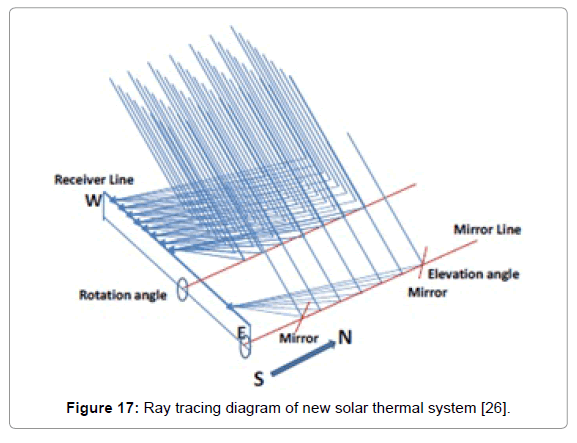
• Modified Stirling Dish engine model with addition of thermal storage in it is being proposed by C. E. Andraka in his publication [25,26]. Also the use of ARPAe HEATS project which is a patent of Sandia National Laboratory increases the efficiency by 3% as compared to the existing design as claimed by the author (Figure 17).
Figure 17: Ray tracing diagram of new solar thermal system [26].
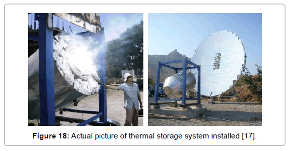
• Another upcoming technology in CSP is Scheffler dish which concentrates light onto a fixed point. India-One is a 1 MWe plant consisting of 770 Scheffler dishes of 60 m2 collector area located at Abu Road, Rajasthan, India (Figure 18).
Figure 18: Actual picture of thermal storage system installed [17].
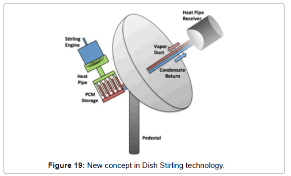
• Modified Stirling Dish engine model with addition of thermal storage in it is being proposed by C. E. Andraka in his publication [26]. Also the use of ARPAe HEATS project which is a patent of Sandia National Laboratory increases the efficiency by 3% as compared to the existing design as claimed by the author (Figure 19).
Thermodynamic Calculations of Heat Engine Working on Stirling Cycle
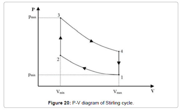
Consider a Stirling cycle formed by combination of four different processes namely Isothermal Heat addition, Isochoric Expansion, Isothermal Heat Rejection and Isochoric compression indicated by process 3-4, 4-1, 1-2 and 2-3 respectively (Figure 20).
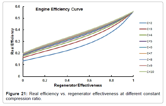
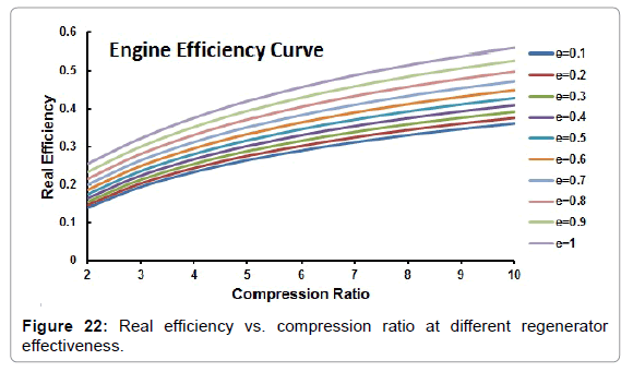
Assuming Air as an ideal fluid in a heat engine working on Stirling cycle, the ideal and real efficiencies as a function of regenerator effectiveness can be considered by following equations:
 (3)
(3)
 (4)
(4)
 (5)
(5)
Where,
TH=Temperature of Hot end of engine;
TL=Temperature of the cold end of engine;
TR=Temperature of the regenerator coil inside engine;
K=Adiabatic constant, for air its value is taken as 1.4;
C=The compression ratio whose value can be changed according to the pressure developed inside engine;
∈regenrator: Effectiveness of the regenerator coil.
From these formulas, we found that the effect of regenerator effectiveness on the overall thermal efficiency of the engine is observed in below two plots (Figures 21 and 22).
Conclusion
After reviewing the current technology and market conditions it can be said that no technology has yet proven itself reliable to take over conventional fuel for meeting the energy demand of India. Photovoltaic as well as CSP are having its Capacity utilization factor very low and hence it can only compensate day load, considering there is no economical solution of energy storage presently available. Hence it is difficult to achieve the target of 100 GW of Solar unless and until a techno economical solution is not produced on commercial scale for Indian Climatic conditions.
Future Scope
According to the Thermodynamic analysis of the Stirling cycle, it can be said that if an engine is made to work on this cycle than it can produce energy more efficiently than any other heat engines available today. Also there is a large scope of increasing the effectiveness of regenerator which can lead to efficiency more than 55% which is depicted from the graphs shown above. Also not only for generating power but also for hybrid-electric automotive applications, the Stirling engines are not only almost twice as efficient as modern spark ignition engines, but because of continuous combustion it burns fuel completely. So advancement and development of efficient Stirling engine will not only solve the problem of energy deficiency but also make the automobile vehicles more efficient than what they are currently which ultimately decreases the carbon emission. At last it can be said that Stirling inherent a great potential in CSP technology and will provide an access to inexpensive solar energy and least expensive alternative for solar energy electric generation applications in the range of 1 kWe to 100 MWe.
References
- Garg P (2012) Energy scenario and vision 2020 in India. J Sust Energ Environ 3.
- https://curry.eas.gatech.edu/Courses/6140/ency/Chapter3/Ency_Atmos/Radiation_Solar.pdf
- Wolff G, Gallego B, Tisdale R, Hopwood D (2008) CSP concentrates the mind. Renewable Energy Focus 9: 42-47.
- Bohra R (2014) Performance Analysis of 1MW SPV Plant; Temperature Corrected PR.
- Haaren RV (2014) Utility Scale Photovoltaic Plant Variability Studies and Energy Storage Optimization for Ramp Rate Control.
- https://blog.pmanifold.com/2011/09/bid-analytics-for-jnnsm-batch-1-solar.html
- MNRE (2012) Jawaharlal Nehru National Solar Mission Phase II – Policy Document.
- https://www.nrel.gov/csp/troughnet/pdfs/2007/smith_infinia_dish_stirling.pdf
- Concentrating Solar Power: Technologies, Cost, and Performance (2012) In: Sun Shot Vision study, pp: 97-121.
- Pheng LG, Affandi R, Ab Ghani MR, Gan CK, Jano Z, et al. (2014) A review of Parabolic Dish-Stirling Engine System based on concentrating solar power. TELKOMNIKA (Telecommunication Computing Electronics and Control) 12: 1142-1152.
- Tamaura Y, Shigeta S, Meng QL, Aiba T, Kikura H (2014) Cross Linear Solar Concentration System for CSP and CPV. Energy Procedia 49: 249-256.
- Andraka CE (2014) Dish Stirling advanced latent storage feasibility. Energy Procedia 49: 684-693.
- Thombare DG, Verma SK (2008) Technological development in the Stirling cycle engines. Renew Sustainable Energy Rev 12: 1-38.
Citation: Vyas A, Panchal K (2016) Analysis of Various Methodologies for Solar Power Generation: Applicable to Meet the Energy Demand of Developing Country like India. Innov Ener Res 5: 149
Copyright: ©2016 Vyas A, et al. This is an open-access article distributed under the terms of the Creative Commons Attribution License, which permits unrestricted use, distribution, and reproduction in any medium, provided the original author and source are credited.
Share This Article
Recommended Journals
Open Access Journals
Article Usage
- Total views: 18884
- [From(publication date): 0-2016 - Mar 31, 2025]
- Breakdown by view type
- HTML page views: 17595
- PDF downloads: 1289

