Air-conditioning based on Peltier Effect
Received: 03-Sep-2021 / Accepted Date: 16-Sep-2021 / Published Date: 23-Sep-2021 DOI: 10.4172/2576-1463.1000247
Abstract
An attempt has been made to develop an air conditioning system based on the thermoelectric effect which can work on a smaller scale more efficiently than the existing systems based on the same principle (The Peltier Effect). It has got an effective new concept for the desired effect. In this system, heat is extracted from one side of a Peltier module generally termed as the cold side of the same and the extracted heat is supplied to another side of the Peltier module (Cold Side) under the action of the Peltier effect. The cold side so formed is used to cool the water so that the water can absorb heat when circulated through the copper tube winding placed in front of the main fan, this ultimately enables the main fan to deliver cold air. Similarly, by reversing the polarity of the current being provided to the Peltier module one can convert the cold side of the module to the hot side and vice-versa, in this way one can get cold and hot air as per the requirement.
Introduction
This paper deals with the explanation of the development of a project which is aimed at providing air-conditioning systems economically as well as eco-friendly. It utilizes the thermoelectric effect for producing a cooling effect. Since there is no refrigerant used in this system, therefore, it does not contribute to ozone layer depletion. However, it has a low coefficient of performance when compared with vapour compression systems [1].
Components
The following components are directly or indirectly related to this system.
1. Peltier module (TEC1-12706)
2. Heat sink
3. Muffin fan
4. Water reservoir
5. Mini water pump
6. Power supplies
7. Copper tube winding
8. Flexible PVC tube
9. Main Fan
Construction
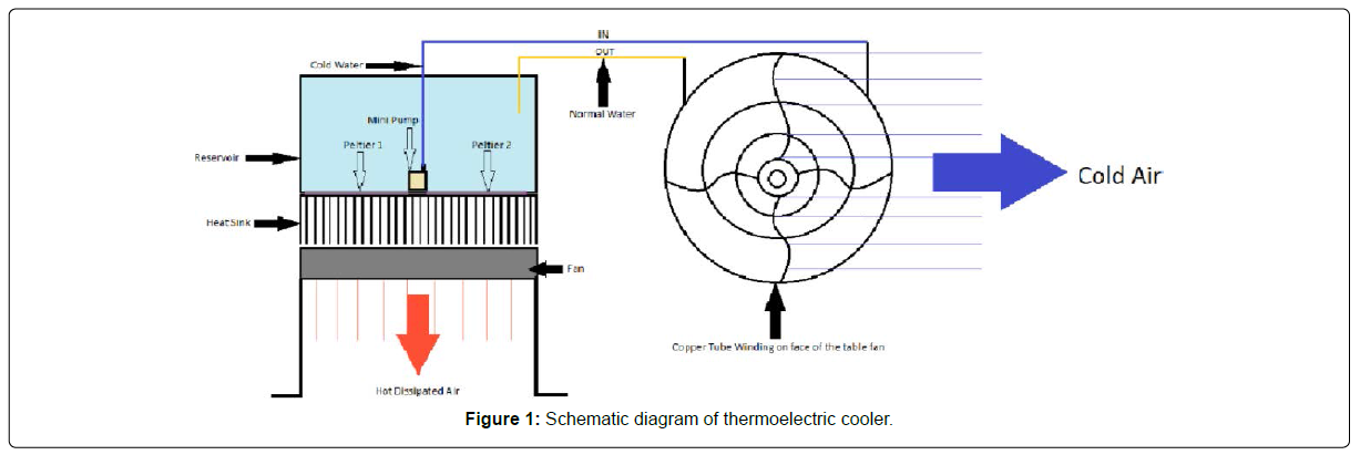
The above diagram shows the proper arrangement of the various components used in this project. Now, we shall begin step-by-step (Figure 1).
1. Firstly, the fan used for forced convection is mounted on a stand of 100 mm Length above the ground level for proper dissipation of heat.
2. Two Aluminium Heat Sink is placed above the ambient zone of the fan.
3. On the flat surface of the heat sink, two Peltier modules are pasted such that their hot side makes proper physical contact with the flat surface of the heat sink.
4. Peltier modules are connected electrically in parallel to the DC 12V 2A power supply.
5. The base of the reservoir has two squared holes to accommodate Peltier modules and to avoid leakage of the water a suitable adhesive has been used.
6. This reservoir has been placed above the heat sink.
7. Water is filled in the reservoir.
8. The reservoir has a mini water pump at its base.
9. PVC Pipe is connected to the two ends of the Copper Tube Winding.
10. One end of the PVC pipe is connected to the pump.
11. Another end of the PVC pipe is placed inside the reservoir to provide a way for the water to come out from the winding.
12. Copper winding is mounted on the face of the table fan.
Assembly
Components are assembled in the following manner
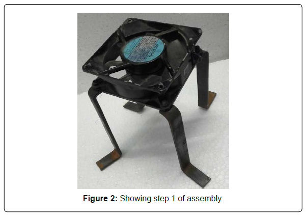
1. In the first step muffin fan is fixed on the prepared stand of 100 mm height as shown below utilizing screws and nuts (Figure 2).
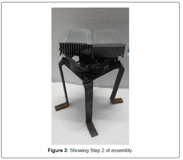
2. In step 2 Heat sinks are assembled on the muffin with the help of m-seal (adhesive) as shown below (Figure 3).
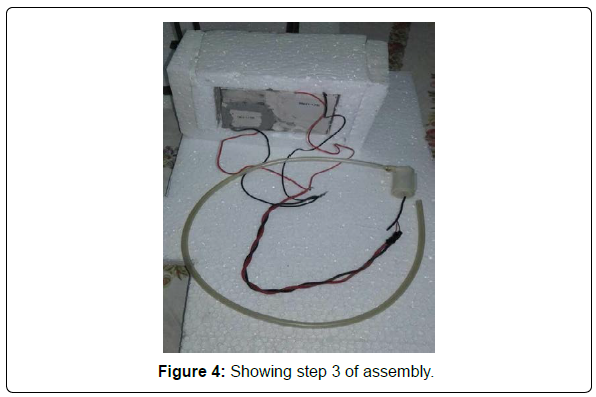
3. In step 3 of the assembly thermopiles or Peltier modules are placed on the bottom surface of the reservoir by cutting a suitable geometrical shape and placing the modules at the cut-out portion by suitable adhesive such that there is no leakage as shown below (Figure 4).
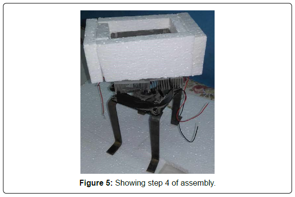
4. In step 4, Thermally insulated (Thermal insulation has been achieved by pasting thermocol on the walls of the reservoir) and thermopiles fitted reservoir is placed on the heat sink as shown below (Figure 5).
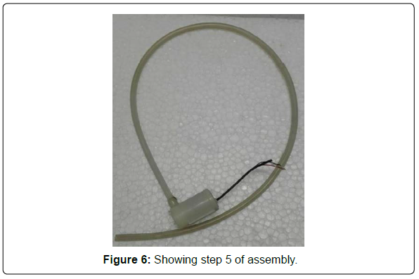
5. In step 5 PVC tube is connected to the outlet of the mini pump as shown below (Figure 6).
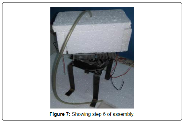
6. In step 6 mini pump fitted with the PVC tube is placed inside the reservoir and reservoir is closed with the help of a thermocol sheet and PVC tube is taken out of the thermocol sheet as shown in the figure below (Figure 7).
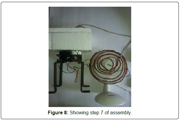
7. In this step PVC Pipe from the mini water pump is connected to the copper tubing as shown in the figure below (Figure 8).
Working
Woking of this system can be explained by considering the following points.
1. On passing a direct current of specified values through thermopiles results in the formation of hot and cold zone on the opposite faces of each thermopile [2].
2. Since it has been cleared from the construction of this project that the thermopiles (TEC1-12706) are placed on the bottom of the reservoir in such a manner that the cold side of each thermopile makes direct physical contact with the liquid or water present in the reservoir, this results in cooling of the liquid.
3. The cold liquid or water is now pumped up with the help of a mini-pump placed inside the reservoir through a PVC pipe.
4. PVC pipe provides cold liquid or water away to the copper tubing placed in front of the fan.
5. Cold liquid or water while flowing through the copper tubes absorbs heat from the copper tube and hence ultimately the copper tubes are cooled.
6. The temperature of copper tubing is low than the surrounding atmosphere so it absorbs heat under the effect of the principle of calorimetry from the air coming out of the main fan.
7. In this way, we can get cold air.
8. Now, we shall begin with the explanation of the removal of heat generated on the hot side of the thermopile.
9. For this purpose, we shall consider the heat sinks which are provided below the reservoir in such a manner that there exists a physical contact between the flat surface of the heat sink and the hot side of the thermopile [3].
10. The heat generated on the hot side of the thermopile flows through the heat sink following the equation of the thermal conduction.
11. This results in the heating of the heat sinks.
12. Now, the muffin fan placed just below the heat sink as shown in the assembly of the project comes into action it sucks air from the air voids in the heat sink [4].
13. Since the air present in the air voids of the heat sink is hot due to the heat of the heat sink [5].
14. When this air is sucked by the muffin fan then fresh air from the atmosphere occupies the space of air voids present in the heat sink. And again the same process occurs.
15. This process goes on as long as there is suction produced by the muffin fan.
16. In this way heat generated on the hot surface of the thermopile is dissipated into the atmosphere.
Advantages
• Eco-friendly
• No moving parts.
• Cheap
• Portable.
• Compact in size.
• Low power consumption
Disadvantages
• Low efficiency.
• An appropriate cooling system is essential.
References
- John, Daniel Stockholm (1992) Thermoelectric Modeling of a Cooling Module with Heat Exchangers, pp. 140 146.
- https://electronics.stackexchange.com/questions/185505/tec-12706-not-drawing-more-than-1-6a-when-powered-by-a-12v-pc-smps
- http://www.phy.olemiss.edu/~cremaldi/PHYS417/Seebeck%20and%20Peltier%20Effects.pdf
Citation: Qamar W (2021) Air-Conditioning Based on Peltier Effect. Innov Ener Res, 10: 247. DOI: 10.4172/2576-1463.1000247
Copyright: © 2021 Qamar W. This is an open-access article distributed under the terms of the Creative Commons Attribution License, which permits unrestricted use, distribution, and reproduction in any medium, provided the original author and source are credited.
Share This Article
Recommended Journals
Open Access Journals
Article Tools
Article Usage
- Total views: 1940
- [From(publication date): 0-2021 - Mar 28, 2025]
- Breakdown by view type
- HTML page views: 1374
- PDF downloads: 566
