Research Article Open Access
A Case Study of Assessing Button Bits Failure through Wavelet Transform Using Rock Drilling Induced Noise Signals
Kawamura Y1*, Jang H2, Hettiarachchi DS2, Takarada Y3, Okawa H4 and Shibuya T51Graduate School of International Resource Sciences, Akita University, Japan
2Department of Mining Engineering & Metallurgical Engineering, Western Australia School of mines, Curtin University, Australia
3Mitsubishi Materials Corporation, Japan
4Graduate School of Engineering Science, Akita University, Japan
4Department of Intelligent Interaction Technologies, University of Tsukuba, Japan
- *Corresponding Author:
- Kawamura Y
Graduate School of International Resource Sciences
Akita University, Japan
Tel: +81 (18) 889 2258
E-mail: kawamura@iit.tsukuba.ac.jp
Received Date: March 20, 2017; Accepted Date: March 24, 2017; Published Date: March 28, 2017
Citation: Kawamura Y, Jang H, Hettiarachchi DS, Takarada Y, Okawa H, et al. (2017) A Case Study of Assessing Button Bits Failure through Wavelet Transform Using Rock Drilling Induced Noise Signals. J Powder Metall Min 6: 162. doi:10.4172/2168-9806.1000162
Copyright: © 2017 Kawamura Y, et al. This is an open-access article distributed under the terms of the Creative Commons Attribution License, which permits unrestricted use, distribution, and reproduction in any medium, provided the original author and source are credited.
Visit for more related articles at Journal of Powder Metallurgy & Mining
Abstract
Finding the precise moment of button breakage of bits during drilling, with the experience of drill rig operators is a serious concern for modern vibrant mining industry. This research proposed a new methodology to find the failure of button using the sound generated by rock-bit interactions. The experiment is conducted by the video and sound data recorded during a drilling process in an underground mine, that uses a Sandvik AXERA7 twin boom jumbo drill rig and Polycrystalline diamond (PCD) tapered button bits. Signal analysis techniques such as Fourier transform and Wavelet transform are utilised to analyse the hectic noise signal recorded. The analysed results are shown that Wavelet Transform is much more effective in finding singularity points such as chipping or breakage of a button in compared to the Fourier Transform. The outcome of this analysis, which is the peak intensity at the breakage point, was correlated to the average intensity of the sound wave using moving average method. The results suggest that the noise generated during the drilling process can be used to detect the condition of the drill bit.
Keywords
Hard rock drilling; Button bit; Sound, Signal processing; Early diagnosis
Introduction
Among the mining operations, hard rock drilling is a crucial stage that guides the extraction of valuable minerals. Drilling always creates noise irrespective of the material to be drilled. This noise is usually generated by the interactions between the drill bit and the drilling surface; as such the noise emitted is different from material to material based on the physical properties of those surface and drill bit. As tapered button bits can be used in medium to hard rock drilling for the uniaxial compressive strength of rocks between 80-200 MPa, it is very popular in modern mining industry [1]. Although a given cutting process consists of a variety of sub processes such as indentation, cutting, crushing, ploughing, grinding and shearing, it is the torque on the bit(Horizontal torque force) and the weight on the bit(Vertical thrust force) which plays the most decisive role on fragmentation of rock particles [2]. Between these two forces the vertical thrust force contributes more towards the penetration rate and the wearing of bits, rather than horizontal torque force [3]. These two forces contributes to the unwanted failures in bits which are chipping of buttons, cracking the carbide, buttons shearing offs, or crushing down buttons to the level of the body of the bit. If one button fails during its operation, it could trigger the failure of the other buttons of the same bit. Thus, it is vital for the operator to identify the precise time of the button breakage to evade further damage to the bit, which will ultimately aid to the profit of the company. Currently almost all drill rig operators in hard rock drilling generally count on their experience to detect any abnormalities in drilling tool conditions, which includes the wear and the breakage of buttons. This practice is subjective and susceptible to errors. With the dynamic conditions of modern mining industry, it is important to introduce a reliable method to perceive defects in drilling conditions to gain prime performance. Over the years sound detection and signal processing techniques have been used in relation to assessing the condition of drilling tools. These techniques, their advantages and disadvantages are discussed in the following section.
Signal Processing Techniques
Rock drilling sound is mainly generated by the interactions between the rock and the bit during the drilling operations. These signals comprise of both the wanted data (noise generated by rockbit interactions) and unwanted data (noise generated by the engine of the drill rig, motors, compressors, etc.). Consequently, it is difficult to detect abnormal conditions during a real time process, because of the complexity of the sound. A simple microphone can detect a series of quick high pitched sounds, whose frequencies can be much higher than the vibrations. Thus, the microphone is an inexpensive solution in chatter recognition, in compared to the other sensors such as acoustic sensors or accelerometers [4]. The sound signal has been extensively used in various researches in milling and metal cutting processes. Lu and Wan [5] proposed a method to monitor the tool wear in micro milling of SK2 steel. In their research they used a special microphone with the bandwidth of 80 kHz. Weller et al. [6] experimented about the sound generated by a worn tool and concluded that sound generated in processes could be applied to detect tool condition in metal cutting operations. Gradl et al. [7] used the sound signal to determine the characteristics of drill bits and has shown that the noise generated by hard rock drilling is related to the design of the bit. Although, the microphone in detecting sound signal is effective and has been widely used, it has some restrictions such as directional considerations, low frequency response and environmental sensitivity [8]. The noise generated by the neighbouring surrounding can influence the frequency region of 0 to 2 kHz of the signal [9] and it is difficult to detect the frequencies below 100 Hz with the use of microphones [4]. Signal analysis techniques are used to convert the hectic original signal to a simple and effective signal by extracting and enhancing the relevant data. The improved signal can illustrate the abnormalities and dominant features of the original busy wave. Hence, it is considered as one of the main methods used for fault diagnostics and condition monitoring. Fourier Transform (FT) and Wavelet Transform (WT) are two main methods in signal processing, which are widely used in condition monitoring and fault diagnostics. Fourier Transform is considered as the foundation for modern signal processing, which transforms the time domain signal in to a frequency domain signal and it is attained by the inner product of the signal with a sinusoidal wave [10]. The mathematical representation of the FT is shown in equation (1).
 (1)
(1)
 (2)
(2)
Here,  is the Fourier transform of the signal f (t).
As s standard technique of FT, Fast Fourier Transform (FFT) has been widely used in various engineering fields as a signal processing method. Lu and Wan [5] used FFT to transform the sound signal to its frequency components to monitor the tool condition. Li and Li [11] highlighted that failure of bearings could be found based on the distinctive frequencies using FFT. Although FT is one of the most recognised methods in signal analysis, it does not possess the ability to expose the characteristic information of non-stationary signals [12]. Moreover, the FT cannot define the characteristics of the temporary signal sufficiently in lower frequencies, because it calculates the averaged frequency composition over the duration of the signal [13]. Hence the use of Wavelet Transform (WT) has become more popular with non-stationery signals analysis.
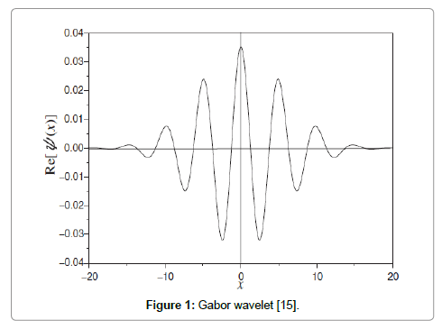
Wavelet Transform is a mathematical process which converts a time domain signal in to different frequency groups [14]. WT has been developed for the time-frequency analysis and it demonstrates the intensity of the waveform for different time and frequencies. Gabor–wavelet is one of the most appropriate mother-wavelet to analyse time-frequency spectrum [14]. Hence, in this research Gabor-wavelet has been used as the mother-wavelet φ(x). Equation (3) shows the algorithm of Gabor-wavelet, which has been used for this research (Figure 1).
 (3)
(3)
The form of Gabor wavelet for σ=8, which is used for the wavelet analysis in this research is shown in Figure 1.
 (4)
(4)
 (5)
(5)
Equations (4) and (5) shows the wavelet transform related with function (a), where σ is a constant, t is time, α is scale parameter, and b is shift parameter and 1/a shows angular velocity. With the variations of the frequency of the signal, the time frequency resolution of the WT fluctuates. Wavelet reaches high time resolution and low frequency resolution at high frequencies and opposed reaction in low frequencies [12], which gives WT a distinctive advantage over the other signal analysis methods in fault diagnostics. Moreover, WT is a useful tool in singularity detection, which plays a crucial role in fault diagnostics. Typically the peak points can be occurred in output signals, at a moment of a fault occurred for example, chipping of button in bits or tool breakage, which are usually singularity points. However, the polynomial trends in the signals can disguise the weak singularities, where WT eliminates the polynomial trends and highlight the singularity points in signals in contrast to FT. The experiment was conducted at an underground mine site, to detect the exact time of button failure of a drill bit by analysing the sound generated during the drilling process using signal processing techniques.
Experimental Setup
Study area description
The sound and video data recorded using a GoPro camera by Mitsubishi Materials Corporation was used for the analysis. The data was recorded during real time drilling of waste rock in an underground mine site, for a 45 mm PCD button bit. Table 1 illustrates the specifications of drilling (Table 1).
| Parameters | Description/Measurement |
|---|---|
| Type of Drill Rig | Sandvik AXERA 7 twin boom Jumbo drill rig |
| Type of bit | PCD tapered button bit |
| Rock type | Waste rock |
| Diameter of bit | 45mm |
| Percussion pressure | 160 bar |
| Feed pressure | 80 bar |
| Rotation pressure | 55 bar |
| Water pressure | 18 bar |
Table 1: Drilling specifications.
Apparatus setup
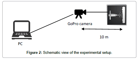
A GoPro camera was mounted on the top of the windscreen of the drill rig to capture the video and the sound of drilling. The camera has recorded a video of 170 degrees field of view with 1280 × 720 pixels and 60 frames per second. GoPro has a built-in mono microphone that recorded the sound using 128 kbps Advanced Audio Coding (AAC) compression at 48 kHz sampling rate. The data recorded was transferred to a personal computer for the analysis. Figure 2 shows the schematic view of the experimental setup (Figure 2).
Experimental procedure
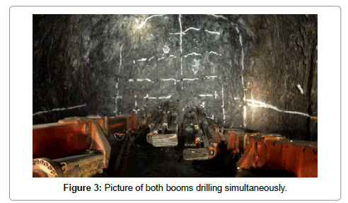
Four meters length holes were drilled using both booms simultaneously as shown in Figure 3. Upon inspection of both booms after 1287.0 s from start, one gauge button of the right boom bit was identified to be broken. The sound data was extracted from the recorded video data and then the sound data was converted to a Comma Separated Values (CSV) format to import the data into OriginPro and GeoLab-analyser softwares for analysis (Figure 3).
Results and Discussion
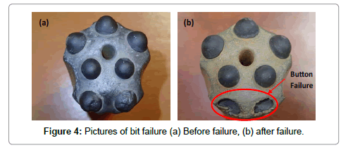
The sound data was extracted from the video recorded during a drilling process in an underground mine is used for the analysis. Figure 4a and 4b show the pictures of the bit before and after the breakage of the button respectively. Signal processing techniques such as time series analysis, FFT analysis and Wavelet analysis were used to find the precise time of breakage of button. This section presents the results of the above mentioned signal processing techniques and moving average method in subsections 4.1, 4.2, 4.3, and 4.4 respectively (Figure 4a and 4b).
Time series analysis
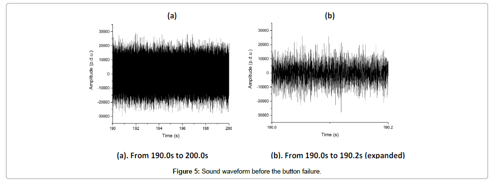
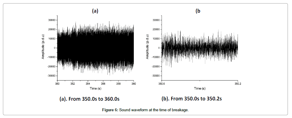
Time series analysis was carried out for the data before the breakage and after the breakage of gauge button to identify the feasibility of detecting differences between the two waveforms. Figure 5a and 6a shows the waveform of the sound signal of drilling before and at the time of breakage respectively. The amplitude of the time series before breakage oscillates between 28999 and -30059 procedure defined units (p.d.u) and the sound waveform after the breakage displays a maximum of 28822 and a minimum of -29668 p.d.u. The average amplitude for both the waveforms fluctuates between 0.2 to -0.2. Thus, makes it challenging to differentiate the breakage point by analysing the statistics of the time series (Figure 5a and 5b). Further, as can be seen from Figures 5b and 6b, which are the expanded views of Figures 5a and 6a respectively, we concluded that the time series analysis cannot be used to identify the breakage of buttons of a bit because the polynomial signals could disguise the weak singularity points (Figure 6a and 6b).
Fast fourier transform analysis
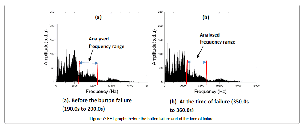
Fast Fourier Transform analysis was conducted to transform the time domain data in to the frequency components. Figure 7a shows the frequency spectrum of the data before the gauge button breakage and Figure 7b shows the frequency spectrum at the time of gauge button breakage. The shape of the graphs in Figure 7a and 7b are virtually identical, and that makes it difficult to visualise any abnormalities which occurred at the point of breakage of the button. However, a slight alteration in amplitude was identified after the breakage of button, for the frequencies more than 4 kHz. Thus the amplitude was statistically analysed for frequencies ranging from 4.2 kHz to 8.2 kHz. It shows that there is a significant escalation in average amplitude in the 5.7 kHz to 6.2 kHz frequency range after the breakage of button. However, the exact time of breakage was not discovered because of the incapability of FFT in detecting a singularity point in a wide range of frequency distribution (Figure 7).
Wavelet analysis
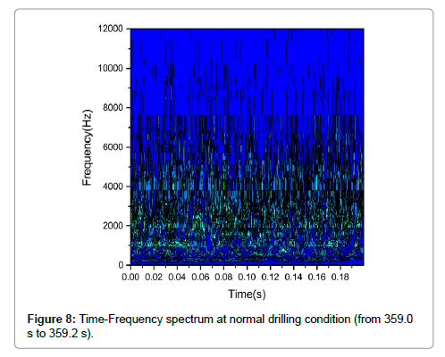
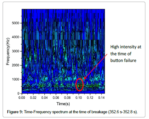
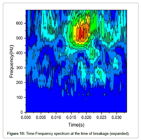
Wavelet transform converts the time domain signal into different frequency groups and shows the fluctuations of the intensity of the wave with the changes of time and frequency. Figure 8 shows the time frequency spectrum of a standard drilling condition and Figure 9 shows the time-frequency map of the time period between 352.6 s to 352.8 s, which indicates the breakage of the gauge button (Figures 8-10). Figure 10 illustrates the time - frequency spectrum of 0 to 700 Hz at the time of breakage. The peak point, which is a high intensity point in the time – frequency map usually occurred in output signal at a moment of breakage. Thus it is obvious that the button breakage occurred at 352.8 s as the high intensity point can be seen around 500 Hz to 600 Hz in Figure 9. This is further evidence to the visual observation at 1287.0 s which was discussed in section 3. Further this result will be correlated to the average intensity between the frequencies of 5.7 kHz to 6.2 kHz by analysing the wavelet matrix in the following section.
Moving average
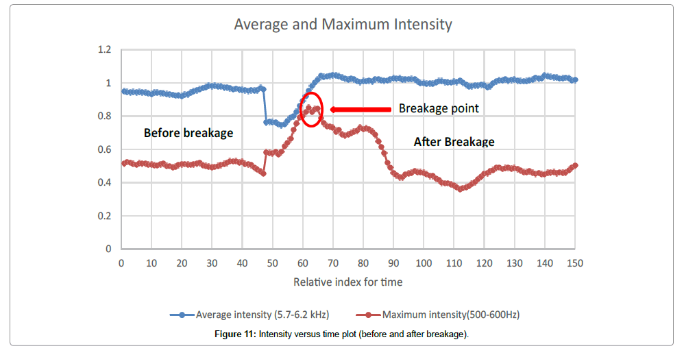
Moving average is a statistical method which can be used to smooth out the data and to understand the trends [15,16]. To find out the trend of maximum intensity, the wavelet matrix was analysed between 500 Hz to 600 Hz because the button breakage occurred within this frequency range. Then two time arrays, between two predefined times before the breakage (190.0 s to 199.2 s) and from the breakage point to a different predefined point (350.0 s to 360.0 s) were defined. For these two time arrays maximum intensity and average intensity were determined for 500 Hz to 600 Hz and 5.7 kHz to 6.2 kHz frequency ranges respectively. For all the values in those four situations, 9 point moving average was calculated. Figure 11 shows the 9 point moving average of maximum intensity and average intensity for the defined two time arrays and frequencies (Figure 11).
There is a singularity point at 352.8 s, as can be seen in Figure 11. The average intensity between 5.7 kHz to 6.2 kHz relates to the trend of maximum intensity, as there is a significant escalation in average intensity after 352.8 s. Before the breakage average intensity retains around 0.9 to1.0 and it increases up to 1.0 to 1.1 ranges after the breakage.
Conclusions
Detecting the precise time of breakage of a button of drill bits in hard rock drilling is vital for the prime performance in mining industry, as the breakage of buttons affect financial losses for the mining companies. However, it is difficult to identify the exact time of breakage with the experience of drill rig operators. Thus, a more reliable method is desired. This research was carried out to find whether it is possible to detect the precise moment of button breakage of bits during the drilling process, by using the sound generated by rock-bit interactions. The sound data was extracted from the video data recorded during a drilling process in an underground mine. The data was analysed with signal processing techniques, which are time series analysis, Fast Fourier Transform and Wavelet Transform. The outcomes of the experiment show that the time series analysis cannot distinguish the breakage point because the polynomial sound signal disguises the weak singularity points. On the other hand robust analysis of Fourier Transform shows the variations in amplitudes of dominant frequencies after the breakage of the button. However, FFT cannot detect a singularity peak point in a wide range of frequency distribution. In compared to other two methods results demonstrates that, high amplitude generated at the point of breakage can be detected by analysing the audio signal with the use of Wavelet Transform. It can be also concluded that Wavelet Transform is a much better signal analysis technique for singularity detection in contrast to Fourier Transform. This research provided an expectation in detecting the button breakage of bits precisely; however, further research has to be performing under different conditions to reach a more accurate conclusion.
Acknowledgement
The authors would like to thank Mitsubishi Materials Corporation for the support given on collection of data.
References
- Mitsubishi Rock Tools .Accessed on 27th July 2015.
- Rao K, Bhatnagar A, Misra B (2002) Laboratory investigations on rotary diamond drilling. Geotechnical & Geological Engineering 20: 1-16.
- Huang S, Wang Z (1997)The mechanics of diamond core drilling of rocks. International Journal of Rock Mechanics and Mining Sciences 34: 134. e1-134. e14.
- Cheng K (2008) Machining dynamics: fundamentals, applications and practices. Springer Science & Business Media.
- Lu, MC, Wan BS (2013) Study of high-frequency sound signals for tool wear monitoring in micromilling. The International Journal of Advanced Manufacturing Technology 66: 1785-1792.
- Weller E, Schrier HM,Weichbrodt B (1969) What sound can be expected from a worn tool? Journal of Manufacturing Science and Engineering 91: 525-534.
- Gradl C, Eustes AW, Thonhauser G (2011) An Analysis of Noise Characteristics of Drill Bits. Journal of Energy Resources Technology 134: 013103.
- Kuljanic E, Totis G, Sortino M (2009) Development of an intelligent multisensor chatter detection system in milling. Mechanical Systems and Signal Processing 23: 1704-1718.
- Salgado D, Alonso F (2007) an approach based on current and sound signals for in-process tool wear monitoring. International Journal of Machine Tools and Manufacture47: 2140-2152.
- Zhu K, Wong YS, Hong GS (2009) Wavelet analysis of sensor signals for tool condition monitoring: A review and some new results. International Journal of Machine Tools and Manufacture49: 537-553.
- Li S, Li S (1990) Acoustic emission analysis for bearing condition monitoring. co DTIC p: 249.
- Peng Z, Chu F (2004) Application of the wavelet transform in machine condition monitoring and fault diagnostics: a review with bibliography. Mechanical systems and signal processing 18: 199-221.
- Li X (2002)A brief review: acoustic emission method for tool wear monitoring during turning. International Journal of Machine Tools and Manufacture 42: 157-165.
- Nagayama M, Kawamura Y,Ujihira M (2006) Study on the Detection of Misfiring Cylinder in a Heavy Machinery Multi-Cylinder Diesel Engine under the State of Rotational Fluctuation. SAE Technical Paper.
- Nagayama M, Kawamura Y,Ujihira M (2006) Study on the Detection of Misfiring Cylinder in a Heavy Machinery Multi-Cylinder Diesel Engine under the State of Rotational Fluctuation.
- Karakus M, Perez S (2014) Acoustic emission analysis for rock–bit interactions in impregnated diamond core drilling. International Journal of Rock Mechanics and Mining Sciences 68: 36-43.
Relevant Topics
- Additive Manufacturing
- Coal Mining
- Colloid Chemistry
- Composite Materials Fabrication
- Compressive Strength
- Extractive Metallurgy
- Fracture Toughness
- Geological Materials
- Hydrometallurgy
- Industrial Engineering
- Materials Chemistry
- Materials Processing and Manufacturing
- Metal Casting Technology
- Metallic Materials
- Metallurgical Engineering
- Metallurgy
- Mineral Processing
- Nanomaterial
- Resource Extraction
- Rock Mechanics
- Surface Mining
Recommended Journals
Article Tools
Article Usage
- Total views: 3157
- [From(publication date):
April-2017 - Dec 19, 2024] - Breakdown by view type
- HTML page views : 2441
- PDF downloads : 716

