Research Article Open Access
Electrical Conductivity of Rocks and Dominant Charge Carriers: The Paradox of Thermally Activated Positive Holes
| Nomana Intekhab Hadi1*, Minoru M. Freund1 and Friedemann Freund2 | |
| 1NASA Ames Research Center, Center for Nanotechnology and Advanced Space Materials, Moffett Field, USA | |
| 2Department of Physics, San Jose State University, USA | |
| Corresponding Author : | Nomana Intekhab Hadi Senior Scientist, NASA Ames Research Center Center for Nanotechnology and Advanced Space Materials Moffett Field, USA Tel: +001650-604-5183 Fax: +001650-604-4680 E-mail: nomana.i.hadi@nasa.gov |
| Received October 19, 2012; Accepted November 19, 2012; Published November 21, 2012 | |
| Citation: Hadi NI, Freund MM, Freund F (2012) Electrical Conductivity of Rocks and Dominant Charge Carriers: The Paradox of Thermally Activated Positive Holes. J Earth Sci Climate Change 3:128. doi: 10.4172/2157-7617.1000128 | |
| Copyright: © 2012 Hadi NI, et al. This is an open-access article distributed under the terms of the Creative Commons Attribution License, which permits unrestricted use, distribution, and reproduction in any medium, provided the original author and source are credited. | |
Visit for more related articles at Journal of Earth Science & Climatic Change
Abstract
In this paper we have focused on fundamental processes that are important for understanding the electrical properties of materials, both single crystal minerals and igneous rocks, both laboratory-grown and from natural environments. The prevailing view in the geophysics community is that the electrical conductivity structure of the Earth’s continental crust over the 5-35 km depth range can best be understood by assuming the presence of intergranular fluids and/or intergranular carbon films. Based on studies of melt-grown MgO, magma-derived sanidine and anorthosite feldspar and upper mantle olivine single crystal we present evidence for the presence of electronic charge carriers, the importance of which has been largely ignored. These charge carriers derive from peroxy defects, which are introduced during cooling, under non-equilibrium conditions, through a redox conversion of pairs of solute OH- arising from the solid state dissolution of H2O. It can be shown that, during reheating, the peroxy defects become thermally activated in a 2-step process. Step 2 leads to the release of defect electrons in the oxygen anion sub lattice. Known as positive holes and symbolized by h•, these electronic charge carriers are associated with energy states at the upper edge of the valence band. They are highly mobile. Chemically equivalent to O– in a matrix of O2– they are highly oxidizing. However, though metastable, the h• can exist in minerals, which crystallized in highly reduced environments. The h• appear to control the electrical conductivity of crustal rocks over much of the 5-35 km depth range. We make the extraordinary and seemingly paradoxial claim that MgO crystals, grown from the melt under the viciously reducing conditions of a carbon arc fusion furnace, contain peroxy defects in their crystal structure, hence oxygen in the valence state 1–. When the peroxy defects break up, they release positive hole charge carriers, formally defect electron in the oxygen anion sublattice, equivalent to O– in a matrix of O2–.These positive holes have two outstanding properties: they are highly mobile and highly oxidizing.
| Keywords |
| Electrical conductivity; Igneous rocks; Non-equilibrium conditions; Peroxy defects; Positive holes; Metastable electronic charge carriers; Dc conductivity; Dielectric polarization |
| Introduction |
| For many geophysical processes in the Earth’s crust it is crucially important to understand the nature of the charge carriers, which control the electrical properties of rocks. In this report we focus on conditions in the Earth’s continental crust over the 5-35 km depth range, where most major crustal earthquakes occur. Our goal is to identify the electric or electronic charge carriers that are present or can be activated in this depth range. |
| Any cursory inspection of geological maps reveals how heterogeneous the crust can be. Magneto-telluric (MT) soundings have provided ample evidence for the electrical heterogeneity as a function of depth. However, they have also identified high conductivity zones that seem to consistently exist at certain crustal depth levels, as well as large-scale in homogeneities in the upper mantle. |
| Any electrical charge transport in rocks can be attributed to one or more of the following contributing causes: (i) electrolytic conduction, (ii) electronic conduction, or (iii) ionic conduction. Electrolytic conduction will occur in rocks where aqueous fluids fill pores and the intergranular space, forming an interconnected network. Ionic transport is negligible at the temperatures most relevant for the crustal depth range of interest here but can become locally or regionally important at high temperatures, both in the solid state and with the onset of partial melting. Electronic conduction can occur over the entire temperature range of interest, either through intergranular networks or through the bulk of the rocks. |
| The two most widely proposed causes for variations in electrical properties of rocks in the crust are interconnected networks of aqueous fluids and/or networks of intergranular carbon or graphite films. |
| In this report we present evidence for the presence of powerful electronic charge carriers in minerals and rocks, which have not been recognized in the past. |
| Emphasis on intergranular fluids and on carbonaceous films |
| Aqueous fluids certainly exist in the shallow crust in the form of saline solutions filling the omni-present pore space in rocks. Open pores can form a communicating network through which fluids are able to flow under the influence of tectonic pressure gradients. Such forced fluid flow through narrow pores will produce electrical signals, known as streaming potentials. They arise when cations are preferentially retained along the walls of narrow conduits while anions are swept along with the fluids [1]. Streaming potentials are the foundation of the electrokinetic effect, widely used in prospecting of the shallow crust by magneto-telluric and other techniques as well in attempts to understand pre-earthquake electrical or electromagnetic signals [2-6]. |
| Deeper into the crust, as the overload of the rock column increases, pores that communicate with the surface must close as the difference between lithostatic and hydrostatic pressures becomes too large. Closing occurs around 3-5 km. Below this cap, fluids are at lithostatic pressures. They can either be trapped in situ in sedimentderived formations, which had been transported downward through tectonic processes such as faulting Yardley et al. [7], or be supplied from below through degassing of magmas during crystallization or through mineral dehydration above a mantle plume Vanyan and Gliko [8] or above a subducting slab [9]. The presence of an electrolytically conductive intergranular phase should have a profound effect on the electrical conductivity structure of the Earth’s crust. |
| Two views emerged in the literature regarding the nature of intergranular films. One view emphasizes the presence of “water”. The other view emphasizes the presence of carbon films precipitated in the intergranular space out of CO/CO2–bearing fluids within the stability field of graphite [10-12]. |
| The inferred presence of water has been widely invoked as an explanation for increased electrical conductivities in the crust and the upper mantle [13-20] or to explain high conductivity layers in the crust at a certain depth ranges, around 20 km [13,19,21-23]. The zones of high electrical conductivity seem to correlate with zones of low velocity for seismic waves, though this correlation has been called into question [24]. The presence of water has also been invoked to account for high electrical conductivity along seismically active faults such as the Parkfield section of the San Andreas Fault in California [25]. |
| Intergranular carbon, carbonaceous or graphite films have been considered as an alternative to water [12,26,27]. Carbon films have been invoked in the context of zones of high crustal conductivity around 20 km, the presence of which suggests conduction mechanisms that are not activated in at shallower depth and disappear at greater depth [28-30]. |
| Analytical techniques such as x-ray photoelectron spectroscopy (XPS), secondary ion mass spectrometry (SIMS) or ion probes have indeed provided evidence for carbonaceous surface films a few atomic layers thick after rocks had been fractured in 95% CO2 +5% CO or 5% CH4 gas mixtures at temperatures between 350–500°C [31]. In the Earth crust and upper mantle such films are assumed to have been deposited in situ from fluids containing reduced carbon species such as CO or CH4 that would have percolated through the rocks. Experiments with thin carbon films along the contact between two quartz crystals at 1 GPa have demonstrated that, when the temperature was raised to about 630°C, the graphite films disintegrate and disappear [32]. |
| In the petrological literature a strong case has been made that the stable lower crust should be “dry” and devoid of percolating or stagnant fluid phases [33]. The argument is that, given the prevailing high temperatures, any “water” in these environments will be consumed rapidly–on a geological time scale–by metamorphic reactions leading to hydroxyl-bearing minerals such as amphiboles and mica, which are characterized by low electrical conductivities [34-36]. The case for a “dry” lower crust has sparked an insightful discussion about alternative views [37]. |
| Electrical properties of minerals and rocks–by AC versus DC |
| Numerous laboratory studies have been conducted to characterize the electrical properties of minerals and rocks. Most often the electrical conductivity was measured using ac methods. The reason for preferring is that ac measurements can (i) provide more parameters than dc techniques and (ii) are better suited for experiments under the high temperatures and high pressures needed to explore the electrical properties of minerals and rocks under lower crust and upper mantle conditions [11,21,36,38,39]. |
| When an ac electric field is applied, marked frequency dependence is often observed, which is caused by the complex interplay between conduction and displacement currents. Displacement currents arise from the polarization of electrons, bonds, mobile ions, defects that either have a dipole or develop a dipole in the alternating electric field, charges accumulated along grain boundaries or charges trapped and detrapped at the interfaces between the sample and the electrodes. |
| To appreciate the complexity of the situation we look at the resistivity ρ[Ω cm] or its reciprocal, the conductivity σ[Ω-1cm-1], and at the dielectric permittivity ε[F cm-1]. For a linear system we write the conduction current density Jtotalat time t and the electric displacement D caused by an electric field E: |
| Jtotal=σ E+εδE/δt (1) |
| and |
| D=εE (2) |
| The relative dielectric constant εr of the medium is defined as |
| εr=ε/ε0 (3) |
| where ε0=8.854×10⁻¹² [F/m] is the dielectric permittivity of free space. Conduction currents and displacement currents will be out of phase with each other. |
| The parameters that are actually measured are not the true values but the effective values given by |
| εeff (ω)=ε’(ω)ωε’’ (4) |
| εeff (ω)=ε’(ω)–i(ω)σ’’(ω)/ω (5) |
| The ratio of the imaginary part to its real part defines the phase angle Ψ given as: |
| tan δ=[ωε’’(ω)]/σ’(ω) (6) |
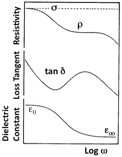
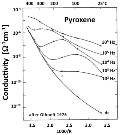
| Figure 1a illustrates how the resistivity ρ, the loss angle tan δ, and the effective dielectric constant εeff depend upon the frequency ω. The “true” conductivity σ is defined only at 0 Hz. Figure 1b shows the conductivity σ of a pyroxene between 25°C to 400°C at frequencies ω between 0 Hz and 106 Hz [39]. A frequency-dependent loss feature is seen, which shifts to higher temperatures with increasing frequencies but also becomes increasingly indistinct. |
| Data as depicted in figure 1b have diagnostic value for the interpretation of laboratory experiments. However, they are not directly useful in the analysis of many sets of field data collected by MT techniques. The reason is that, while the first few hundred meters below the surface can be probed with EM waves in the 1-5 kHz range, low to ultralow frequencies in the Hz, mHz and μHz ranges are needed to penetrate deep enough into the Earth’s crust and upper mantle to send back information about their electrical structures [40]. |
| In order to build the case for dc measurements, it is opportune to look at the electric conductivity of materials from a broader perspective, in particular with respect to their electronic conductivity. |
| Materials as electronic charge carriers |
| Materials can be broadly classified into three groups: metals, semiconductors, and insulators. The three groups differ in the position of their valence bands (VB) and conduction bands (CB) relative to each other on the energy scale. |
| In metals, VB overlaps with CB allowing electrons from the VB to flow over into the CB. The CB electrons are not bound to any particular atom. Instead their wave functions are fully delocalized. |
| Semiconductors have a modestly wide band gap, Eg on the order of 1 eV. Such gaps allow some electrons from the VB to become thermally activated to the CB, where they act as negative charge carriers e’. Around 300 K the thermal energy kT is ~25 meV, where k is the Boltzmann constant, 8.618×10⁻⁵ eV/dEg, and T the absolute temperature. Assuming a Boltzmann distribution, the probability for VB electrons to be thermally activated across Eg is e–Eg/kT. For a 1 eV band gap this means e-40 ~4×0-18at 300 K. Electrons that make the transition to the CB leave behind defect electrons in the VB. The defect electrons are called holes, designated by h•. They carry a +1 charge. Holes in the VB are less mobile than electrons on the CB. |
| In insulators, Eg is wide to very wide, often 5 eV or more. Thus the probability for electrons to be thermally activated from VB to CB becomes vanishingly small. Numerically, for e–Eg/kT ~5 eV, the probability at 300 K or room temperature is on the order of 10-87 and still as low as 10-29 for 900 K or ~630°C. Thus, the electronic conductivity of perfect insulators should be zero. Any observed conductivity has to arise from the presence of defects and/or impurities. |
| Eq. (7) links conductivity to the number density of charge-carrying species n and their mobility μ: |
| σ=n μz2e2/(kT) (7) |
| where z is the valence of the conducting species, e the unit charge, k the Boltzmann constant, and T the absolute temperature. |
| If the conductivity is thermally activated with activation energy Eact, we have: |
| σ=σ0 exp[-Eact/kT] (8) |
| where the pre-exponential factor σ0 is the product of several contributions including μ, z and e. If more than one process controls the conductivity, each with activation energy E1, E2 …, we have: |
| σ=σ1exp[-E1/kT]+σ21exp[-E2/kT]+… (9) |
| Plotting log σ versus 1/T eq. (8) will give a straight line, called an Arrhenius plot, with the slope E act. |
| Eq. (9) will give two or more straight sections corresponding to E1, E2… |
| In semiconductors electrons in the CB, e’, always compete with holes in the VB, h•. The overall conductivity behavior depends on at the number densities of e’ and h•., designated as n’ and n•, and the mobilities, designated as μ’ and μ•. If the product n’μ’ is larger than n•μ•, electrons control the overall conductivity and the semiconductor is n-type. Conversely, if the product n’μ’ is smaller than n•μ•, holes control the conductivity and the semiconductor is p-type. |
| n’μ’>n•μ• n-type (10a) |
| n’μ’<n•μ• p-type (10b) |
| Any semiconductor that is chemically pure is said to be intrinsic. In the intrinsic case, when electrons are thermally promoted across Eg, the number of electrons on the CB will be equal to the number of holes in the VB: n’=n•. Since the mobility of electrons on the CB is always higher than the mobility of holes in the VB, any intrinsic semiconductor will be n-type. While n’ and n• depend exponentially on the temperature, the temperature dependence of the mobilities, μ’ and μ• is weak. By doping an intrinsic semiconductor with aliovalent impurities, it can be made more n-type or p-type depending on the nature and concentrations of the dopants. Aliovalent dopants mean impurities with valencies other than those of the regular lattice constituents of the semiconductor material. However, aliovalency can also involve native lattice constituents in a different valence state. This aspect will play an important role in the discussion below. |
| The electrical conductivity of a material is the sum of the conduction of each type of charge carriers or each type of defects, all acting in parallel: |
| σ=Σσi=Σni zi μi (11) |
| where ni is the concentration of the ih type of charge carrier, zi is the charge, and μi the mobility. |
| Minerals and rocks are “dirty” systems with complex chemistries and defects of many different kinds always present over a range of number densities or concentrations. Each type of impurity or defect contributes to σ, though usually not more than two types will dominate in any given temperature window under a given set of thermodynamic conditions. |
| Igneous rocks: activation energies, charge carrier concentrations, and mobilities |
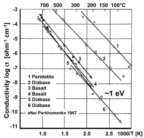
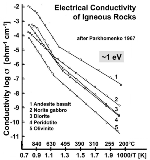
| Figures 2a and 2b show Arrhenius plots for a selection of mafic and ultramafic igneous rocks samples that have been conditioned by cycling them through the temperature intervals under controlled redox conditions, using a variety of heating and cooling rates [41,42]. |
| For all rocks under study σ from below 100°C to about 600-700°C is consistent with eq. (8), i.e. with a single conductivity mechanism characterized by a single value of Eact. This is a very remarkable observation. It means that, within this temperature range, Eact is closely the same for all rocks, ~1 eV, suggesting that, in spite of considerable mineralogical and chemical differences, the conductivity of these rocks appears to be controlled by the same conductivity mechanism over the low temperature region (LT), from below 100°C to 600-700°C. |
| At the same time, different specimens of the same rock can be seen to produce straight Arrhenius plot sections that are shifted parallel to each other on the log σ scale by orders of magnitude. The only reason can be large differences in the magnitude of the values oFΣ0. According to eq. (7) only n and μ, the number densities n and mobilities μ, can make T-dependent contributions to σ0. Since the T- dependence of μ is weak, we can treat μ’ and μ• as approximately constant across the temperature interval of interest here. Hence the differences seen in figures 2a and 2b can only arise from different values of n’ and n•. For instance, the Arrhenius plot for peridotite in figure 2a shows conductivity over the 50-300°C range up to 6 orders of magnitude higher than the conductivity of the peridotite shown in figure 2b over the 100-500°C window. |
| Figure 2b shows that, when the rock samples were heated beyond 550-600°C, straight sections are obtained up to about 1000°C, some with different slopes, suggesting that the high temperature (HT) region is characterized by different conductivity mechanisms with different Eact values. |
| Thus figures 2a and 2b point to two temperature intervals, LT and HT, where different activation energies prevail, E1 in the LT range and E2, E3, E4 … in the HT range. At HT ionic conductivity is known to set in, suggesting different ionic conduction mechanisms with different Eact values. The main “take-home message” for the LT range is that Eact is closely the same for all rocks, although σ0 values vary over orders of magnitude. The constancy of the activation energy Eact ~1 eV across different rock types is as remarkable as the widely different σ0 values within one rock type. |
| Nature of the Charge Carriers |
| Electronic charge carriers in MgO (a Model Insulator) |
| MgO, an II-VI material, is not a semiconductor. With its very wide band gap of about 8 eV, MgO is the most ionic among all alkaline earth oxides with predominantly Coulombic interaction between Mg2+ and O2– [43]. As a main-group element with the electronic configuration 1s2 2s2, Mg has only one stable oxidation state, 2+. Therefore, pure MgO should be a model insulator. |
| Large MgO single crystals can be melt-grown by the carbon arc fusion technique [44]. Crystals are available at nominal 99.9% purity grades, designated as 3N, either undoped or doped with various levels with divalent 3d transition elements Mn, Fe, Co, or Ni. Purer MgO crystals, up to purity grade 99.99%, designated as 4N, are also available in sizes up to several cm3. |
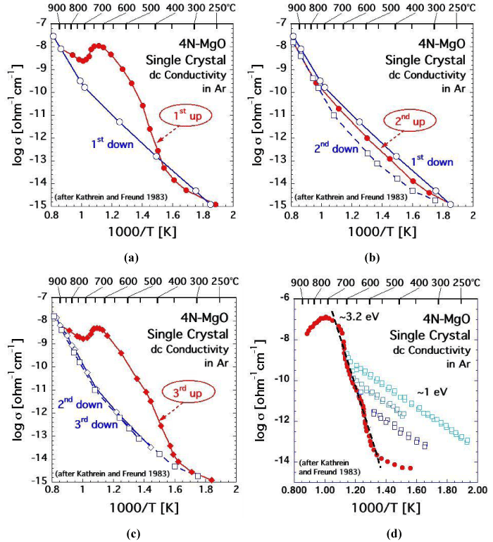
| If MgO single crystals are well-annealed, their electrical conductivity at room temperature can be below 10-16 [O-1cm-1]. However, when heated, MgO single crystals display a striking dc conductivity behavior as illustrated in figures 3a-d for a high purity 4N-MgO crystal measured under the most stringent clean conditions and with a guard electrode to remove contributions from surface conductivity [45]. |
| Upon first heating, starting around 350-400°C, the conductivity of the MgO crystal increases by about 6 orders of magnitude as shown in figure 3a. At the heating rate used in this experiment, 10°C min-1, the conductivity reaches a maximum around 600-650°C and then decreases, only to increase again above 700°C. Around 850-900°C the conductivity joins an Arrhenius straight section that describes the reversible HT conductivity, which is endowed with an activation energy of 2.4 eV. At very slow cooling rates the transition from the HT to the LT mechanism may as low as 500°C [46]. However, at every cooling rate, slow or fast, the HT mechanism is eventually replaced by the LT mechanism, endowed with Eact ~1 eV. The transition from HT to LT usually occurs in the 650-700°C range. In the HT range the electrical conductivity of MgO is controlled by Mg2+diffusion via an Mg2+ vacancy hopping mechanism [47], possibly augmented by O2-diffusion [48]. The nature of the LT 1 eV mechanism has long remained undetermined. |
| If the MgO crystal is reheated immediately after cooling as in the run depicted in figure 3b, the conductivity curve “2nd up” closely follows the LT conductivity behavior observed during first cooling “1st down” and also during second cooling “2nd down”. If, however, the MgO crystal is not reheated immediately after cooling but instead allowed to anneal for several hours or overnight, figure 3c shows a conductivity pattern, “3rd up”, is strikingly similar to the conductivity pattern during the first heating, curve “1st up” in figure 3a. This conductivity hysteresis is reproducible during repetitive heating-cooling cycles, except that the highest conductivity achieved around 650°C slowly decreases with the number of cycles and with the holding time at high temperatures. Another subtle but reproducible feature is that, during cooling, the transition from the HT section to LT section shifts to ever lower temperatures the more often the MgO crystal has been cycled through HT and the longer it has been kept at temperatures >900°C. |
| A similar conductivity pattern has been observed during studies of natural samples [31,49,50], though these studies seem to never have been pursued with as much attention to detail as those of MgO. In the cases reported, mostly with olivine, the high conductivity in the LT range during initial heating was blamed on adventitious surface contamination by carbonaceous films. While surface contamination can never be totally ruled out, even under well-controlled conditions, conductivity measurements can be carried out in such a way that it becomes possible to differentiate between surface contamination and bulk conductivity [45]. |
| For instance, figure 3d shows the conductivity behaviour of the 4N MgO crystal when the heating is intermittently reversed three times within the LT interval, i.e. within the range of the anomalously increasing conductivity, at 540°C, 555°C, and 590°C. Each time, after the intermittent cooling, the MgO crystal was immediately reheated. The results show a series of Arrhenius straight sections, all with the same slope corresponding to activation energy of ~1 eV. Each time, during reheating, the conductivity rejoined the main branch, marked by solid red circles. The main branch is characterized by an Eact value around 3.2 eV. |
| Because this particular experiment was conducted at heating and cooling rates of 20° min-1, the main branch in figure 3d is shifted towards higher temperatures relative to the curves in figures 3a-c, which were conducted at 10° min-1. Except for this experimental artifact, which is due to the thermal inertia of the system, the conductivity patterns are very similar. A conductivity pattern as depicted in figure 3d is inconsistent with surface contamination. Instead it points to two processes, both arising within bulk of the MgO crystal and both working in tandem. |
| Process (i) involves the activation of defects in the MgO structure, which are electrically inactive but release mobile charge carriers as the temperature increases. The activation begins at ~350°C at the 10° min-1 heating rate or ~450°C at the 20° min-1 heating rate. Process (i) is endowed with an apparent activation energy barrier ~3.2 eV. It takes place only after the MgO crystal has been annealed for some time. It operates between 350-600°C during 10° min-1 runs or 450-650°C during 20° min-1 run. Around 600-650°C process (i) comes to an end, suggesting that all available charge carriers have been activated. Above 700°C the conductivity decreases, indicating that the charge carriers activated by process (i) are now being consumed. This is consistent with the aforementioned decrease in maximum conductivity during consecutive heating-cooling cycles. |
| One important observation is that process (i) only comes into effect, if the MgO crystal has been annealed after a prior heating-cooling cycle. The reason is that, once the charge carriers have been activated with Eact ~3.2 eV, they remain active for a sufficiently long time to allow for successive cooling-reheating cycles, during which they will conduct with Eact ~1 eV. If by contrast, the MgO crystal is allowed to anneal, the charge carriers return to an inactive state, from which they can be reactivated with Eact ~3.2 eV, starting around 350-450°C. Therefore, the 3.2 eV activation energy describes two processes in tandem, the “reawakening” of the charge carriers out of their inactive state and the characteristic Eact ~1 eV, with which those charge carriers conduct the current. |
| Process (ii) relates to the current carried by n mobile charge carriers, where n is the number of charge carriers thermally activated through process (i). Those charge carriers require activation energy E2 to conduct the current. |
| Eact ~3.2 eV of process (i) must therefore consist of two separate activation energies E1+E2 ~3.2 eV. Of which E2 ~1 eV is to be assigned to process (ii). Both follow Arrhenius relations. Therefore, to describe the system we can write a relation similar to eq. (9): |
| σ=σ0 exp [-(E1+E2)/kT] (12) |
| The sum (E1+E2), ~3.2 eV, applies to the main heating branch in figure 3d. E2 ~1 eV applies to the cooling-reheating straight sections in figures 3a-d. The value for E1 ~2.2 eV describes the activation energy needed to “re-awaken” the charge carriers out of their inactive state. |
| Furthermore, the anomalous conductivity behavior of the MgO single crystals. MgO crystals that were temperature-cycled in pure O2 exhibit the same conductivity pattern, ruling out that the increased conductivity would be caused by carbonaceous surface films [45]. In summarizing this section we can state with confidence that MgO single crystals, even of the highest purity-grade, exhibit a complex dc conductivity behavior between ambient and 800-900°C. The conductivity increase by orders of magnitude between 300°C and 600- 700°C is not due to transition metal cations in the MgO matrix. Instead it points to the presence of defects, which had not been identified in prior work. |
| Valence changes in the oxygen anion sublattice |
| MgO was the first oxide material for which evidence was obtained that the valence of oxygen anions is not fixed at 2-, as is widely assumed, but can change to the higher oxidation state 1-. When ultrahigh purity Mg(OH)2 was thermally decomposed to MgO+H2O, forming a dilute MgO–H2O solid solution, Mg1–δ (OH)2δO1–2δ, it released copious amounts of H2, 10,000 ppm, even though the transition metal impurity level was <5 ppm, equivalent to a purity grade >99.999% [51]. Since Mg cations are fixed in their 2+ valence state, the only possibility for H+ to be reduced to H2 was to concomitantly oxidize oxygen anions from valence 2- to valencE1-. |
| Follow-on studies with MgO single crystals revealed that the redox conversion takes place in the MgO matrix involving OH-pairs associated with and chargewise compensated by Mg2+ vacancies. During the process two OH– protons are reduced to H, forming H2, while two hydroxyl O2- are oxidized to O-, forming a peroxy anion, O2 2-[52,53]. |
| Using the Kröger-Vinck point defect designation1 we can write this reaction as: |
| The H2 sitting on the Mg2+vacancy site can transition into an interstitial site: |
| where the right side now describes an Mg2+vacancy chargewise compensated by a peroxy anion, O2 2-. If the MgO crystals are very small [53] or if the time for outdiffusion is very long, the H2 can escape from the solid matrix. Such loss of H2 changes Mg1–δ (OH)2δO1–2δ into Mg1–δO. IFΔ«1, the cation-deficient Mg1–δO may also be written as MgO with excess of oxygen, MgO1+δ. |
| MgO is intrinsically diamagnetic. Peroxy anions are diamagnetic, because the two O– are tightly coupled and spin-paired. Upon heating, the spin pairing loosens up and eventually breaks, causing a transition from a diamagnetic to a paramagnetic state and dissociation. Magnetic susceptibility studies have provided information about this transition [53]. Peroxy spin decoupling and dissociation take place in two distinct steps: (i) the peroxy bond loosens up; (ii) full dissociation takes place. Designating as I the peroxy defect as I and as II the transition state, where spins associated with the two O– begin to decouple, we have: |
 (15) (15) |
| During stage II, the wave functions associated with the two O– delocalize over many neighbouring oxygen anion positions, causing anomalies in fundamental physical properties such as in the thermal expansion and in the refractive index [54]. However, at this decoupling stage, there is no significant increase in the electrical conductivity. |
| During stage II, the two O– dissociate. Dissociation involves an electron transfer from a neighboring O2-donates into the [O• VMg O•] x defect. The neighboring O2-, which had donated the electron, thereby turns into an O-, which is no longer bound to the Mg2+vacancy. It becomes an unbound defect electron on the oxygen anion sublattice. The Mg2+vacancy retains one O–, forming a V– center, a point defect widely studied by electron paramagnetic resonance spectroscopy [55,56]. Designating the dissociated state with III we have: |
 (16) (16) |
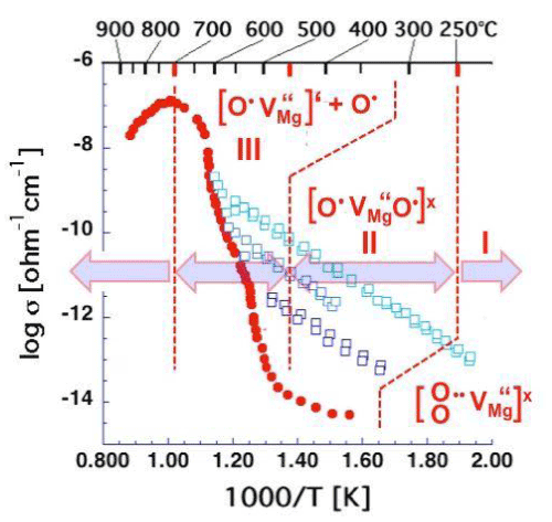
| Figure 4 is a repeat of figure 3d outlining the temperature windows for the transitions between defects I, II, and III. It summarizes the insight gained from a range of studies aimed at understanding the electrical conductivity of nominally high purity MgO single crystals. These studies have identified peroxy defects in the MgO matrix as the cause for the anomalous electrical conductivity behavior. |
| Unbound O– represent defect electrons in the O2- sublattice designated h• [57]. The h• are free to roam–as electronic charge carriers– through the oxygen anion sublattice. Therefore, when the peroxy defects break up, releasing h• charge carriers, the electrical conductivity increases sharply as demonstrated in figures 3d and 4, rising by 6-7 orders of magnitude over a 250°C wide interval, from about 450°C to about 700°C. |
| Close to 700°C the release of h• charge carriers come to completion, marking the end of dissociation of defect II. Above 700°C the conductivity drops. The reason is that another process sets in, namely Mg2+ diffusion, which becomes thermally activated above ~600°C [58]. Mg2+diffusion is essential for non-stoichiometric Mg1-δO to return to equilibrium. It requires annihilation of the excess Mg2+vacancies at the crystal surface, a process that proceeds by way of cation vacancy hopping [59-61]. |
| Thermodynamic equilibrium and non-equilibrium conditions |
| If O– is to be introduced into MgO under thermodynamic equilibrium conditions, highly oxidizing conditions are required [61]. No MgO crystal grown from the melt under highly reducing conditions should contain oxygen in the valence state 1-. Therefore, the presence of peroxy defects appears to be paradoxical and in disagreement with thermodynamics. However, neither the reaction described by eq. (8) nor the loss of H2 as described by eq. (9), or the presence of O–, or the presence of excess Mg2+vacancies in the non-stoichiometric Mg1-δO are in conflict with thermodynamics. The number of Mg2+ vacancies in the MgO matrix is not a reflection of the O2 fugacity at the time of crystallization. It is a consequence of H2O that partitioned into the solid MgO matrix under thermodynamic equilibrium conditions, combined with the reactions described by eqs. (8/9). The reactions occur at temperatures too low for equilibrium to be maintained. |
| When nanocrystalline Mg1-δO produced by the outdiffusion of H2 according to eq. (14) was heated above 600°C, atomic O started to evolve, indicating disproportionation [51]: |
| O2 2–=>O2–+O (17) |
| This is a reaction that allows Mg1–δO to evolve toward the 1:1 stoichiometry that a material like MgO with Schottky defects is supposed to have at thermodynamic equilibrium [62]: |
| Mg1–δO=>MgO+δ/2O2 (18) |
| Confirmation of positive holes by dielectric polarization |
| Electrical conductivity measurements do not provide the sign of the majority charge carriers. If we want to learn more about the nature of the charge carriers, it is advisable to supplement conductivity measurements with corroborating techniques. |
| One option is to conduct Hall Effect measurements, widely used to study semiconductors [63], which provide information about the sign of the majority charge carriers and their mobilities. Another option is to measure the dielectric polarization P, a fundamental property of materials, given by P=ε0 (ε-1) 4π Eext, where ε0 and ε are the permittivity of vacuum and dielectric constant, respectively, and Eext is the externally applied electric field [64]. |
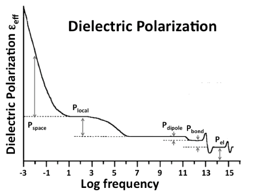
| As illustrated in figure 5 the dielectric polarization Ptotal is composed of several contributions in different frequency ranges. We can identify three contributions characteristic of the bulk, Pel, Pbond, Pdipole, Plocal, and Pspace, plus a sixth contribution, Psurface, which arises from the surface [65]. At high frequencies, in the visible (VIS) region, 1015-1013 Hz, only electrons can respond to the rapidly alternating E field. Their contribution Pel defines the refractive index n. In the infrared (IR) region, below 1013 Hz, atoms linked by bonds or forming dipoles can follow the Eext field, converting energy into atomic vibrations. The sum (Pel+Pbond+Pdipole) defines the dielectric constant, ε, linked to the refractive index n by the Lorentz-Lorenz relation n=√ε. In perfect dielectrics Ptotal will not increase further with decreasing frequency. In reality defects are always present, some of which may have dipoles that can align in the Eext field or possess a local polarizability that is different from that of the surrounding matrix. Their contributions are combined in Plocal. When mobile charge carriers appear, they can form space charges that respond to the external Eext field. Their contribution is designated as Pspace. In the context of this paper Plocal and Pspace are of interest. |
| The sixth contribution, Psurface, arises uniquely from the surface. When a dielectric generates mobile charge carriers, these charge carriers rePel each other in the bulk and are driven toward the surface. The sign of the surface charge is determined by the majority charge carriers, their number density n and mobility μ. According to eqs. (10a/b) the surface charge is positive if n’μ’<n•μ•, indicating p-type, and negative, if n’μ’>n•μ• indicating n-type behavior. |
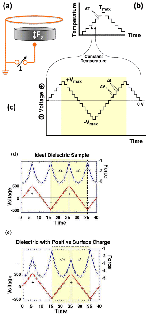
| Figure 6 illustrates the principle of a dielectric polarization measurement, protocol and representative results [64]. Figure 6a shows how the sample is placed between a small gold sphere and an annular gold electrode. Connecting the annular electrode to ground and applying a ± voltage to the small electrode, generates a divergent electric field, which produces a force Fz acting on the sample. In practice the sample is suspended from a microbalance into a small, cup-shaped furnace, which contains both electrodes. Figure 6b shows a temperature-time program with temperature steps, ΔT, typically in 5° or 10°C increments/decrements. During each ΔT step, at constant T, a voltage-time program is applied as shown in figure 6c with typical ±ΔV steps of ±5, ±10, ±20 or ±50 V. |
| In the case of a dielectric with contributions from Pel, Pbond, Pdipole, Plocal, and Pspace, Fz is proportional to the square of the applied voltage leading to parabolas as in figure 6d. In the case of a dielectric with mobile positive charges in the bulk, which make a Psurface contribution, the parabolas are skewed by the addition of a linear term, proportional to the density of the surface charge, as illustrated in figure 6e. |
| Bulk and surface contributions can be separated by forming linear combinations FΣ=1/2(Fz-+Fz+) and |
| FΔ(Fz --Fz +) where Fz + and Fz - are the forces measured with + and – bias, respectively. |
| FΣ depend quadratically on the bias voltage and is given by: |
| FΣ=−∫vol {[Pel+Pbond+Pdipole+Plocal+Pspace]∇}EextdV (19) |
| FΔ depends linearly on the bias voltage and is a unique function of the surface charge density: |
| FΔ=− ∫v [Psurface∇]EextdV (20) |
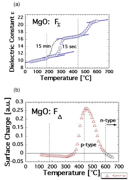
| Figures 7a and 7b show FΣ(T) and FΔ(T) plots of an MgO single crystal, here a 3N-MgO crystal, 99.9% basic purity grade doped with 200 ppm CO2+. FΣ(T) and FΔ (T) graphs of undoped 4N-MgO or of moderately doped 3N-MgO crystals with divalent 3d-transition metal cations are practically indistinguishable. The data were obtained during stepwise heating to Tmax=600°C in N2 atmosphere following the protocol depicted in figure 6b with 15 sec polarization time at each ΔV step during each ΔT step. The dotted line in figure 7a indicates how FΣ(T) changes when the polarization time is increased to 15 min at each ΔV step. The 15 min polarization data were obtained in a separate run over this narrow T interval. Figure 7b indicate the evolution of FΔ(T). The black triangles show FΔ going negative, if heating is continued above 600°C. These data were obtained in a separate run. |
| In Figure 7a the FΣ(T) data are fitted to the dielectric constant ε of MgO, 9.6 at room temperature [66]. At the limit of 0 Hz ε begins to increase around 250°C at 15 sec polarization time or already around 200°C at 15 min polarization time. Around 350°C ε reaches a plateau but exhibits a second stepwise increase beginning around 450°C. The FΔ(T) data in figure 7b indicate a slightly negative surface charge of the MgO up to about 350°C, followed by a pronounced positive surface charge, indicating the onset of p-type behavior. The positive surface charge reaches a maximum about 450°C, then decreases and turns negative above 600°C, indicating n-type behavior. |
| According to eq. (14) FΣ(T) is the sum of the five bulk contributions to Ptotal. Only the last two, Plocal and Pspace, depend on the presence of defects. The stepwise increase in FΣ(T) indicates that these defects are thermally activated. During the first increase, there is no change in FΔ(T), i.e. no activation of mobile charge carriers. This means that the first FΣ(T) increase, which begins at 250°C or 200°C, is due to the thermal activation of defects, which only affect the local polarizability, Plocal. This is fully consistent with the transition of the tightly bound, spin-coupled peroxy defect [O•• VMg“O•]x, state I, to state II, the spindecoupled state [O• VMg“O•]x as described by eq. (15). It is consistent with the absence of any significant increase in the electrical conductivity of the MgO in the temperature range below approximately 350°C as evidenced in figure 3a. |
| By contrast, above 350°C, the electrical conductivity of the MgO starts to increase as shown in figure 3a, indicating the activation of mobile charge carriers. This is consistent with the increase in FΣ(T), due to a contribution of Pspace and simultaneous Psurface contribution as reflected in the change in FΔ(T) in figure 7b. This is consistent with the break-up of the peroxy bond as described by eq. [16], i.e. with the transition of the spin-decoupled state [O• VMg“O•]x to the dissociated state [O• VMg“]‘+O• and activation of mobile positive hole charge carriers h•. |
| Dielectric polarization measurements during cooling show that FΣ(T) is fully reversible under the conditions of the experiments, i.e.under slow stepwise cooling over many hours. The high temperature portion of FΔ(T), the trend from the high positive values around Tmax ~500°C toward negative values at ~600°C, is also reversible. Below ~500°C, however, the surface charge lingers on, causing FΔ(T) to remain positive down to ambient temperatures. At room temperature the surface charge dissipates over the course of hours with about the same time constant with which the electrical conductivity σ(T) recovers during annealing as discussed in the context of figures 3a-c. |
| Positive hole charge carrier activation in feldspars |
| MgO is not the only material that contains peroxy defects and activates positive hole charge carriers at distinct temperature steps upon heating. Silicates also contain peroxy defects, probably in the form of peroxy bridges, O3Si/OO\SiO3 or O3Si/OO\AlO3, replacing O3Si/O\ SiO3 or O3Si/O\AlO3 bonds respectively, or linking [SiO4] groups. |
| In the case of MgO the formation of peroxy defects was linked to the dissolution of H2O and formation of hydroxyl pairs associated with Mg2+ vacancies, OH–, followed by the redox conversion described by eqs. (13/14). Feldspars are tectosilicates, the structures of which consist of [Si, AlO4] tetrahedra 3-dimensionally connected by O3Si/O\SiO3 and/or O3Si/O\AlO3 bonds. If H2O dissolves in a tectosilicate, it will most likely hydrolyze the bonds forming hydroxyl pairs as its primary product: |
| O Si/O\SiO+H O⇔OSi/OH HO/SiO3 (21) |
| The hydroxyl pair on the right hand side of eq. (21) can undergo the same type of redox conversion as OH– pairs in MgO, leading to: |
| O3Si/ HO/SiO3⇔O3Si/OO\SiO3+H2 (22) |
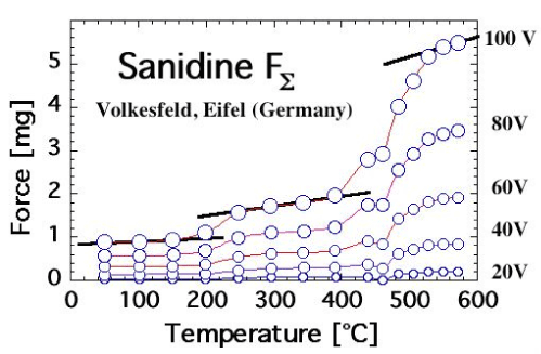
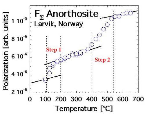
| Feldspars indeed exhibit the same FΣ(T) and FΔ(T) behavior as MgO when heated. This is exemplified in figures 8a and 8b for FΣ(T) of a sanidine single crystal from Volkesfeld in the Eifel volcanic district, Germany [67], and of an anorthosite from Larvik, Norway [68]. The sanidine, K0, 96Na0, 14AlSi3O8, was cut from a very large (40 cm) single crystal extracted from a leucite phonolite tuff [69]. The anorthosite sample consisted of an 8 mm diameter disk, 2 mm thick, cut out of the coarsely polycrystalline Larvik anorthosite rock. Both sanidine and anorthosite samples were transparent or translucent and smoky gray due to the presence of unbound positive holes, which localize at low temperatures at O3Si/O\AlO3 or O3Al/O\AlO3 [70]. Both bleach upon heating beyond 500°C to a light gray color due to the annihilation of positive holes. |
| In both cases, FΣ(T) increases in 2 steps, at 200-250°C and 400-500°C for sanidine and at 100-150°C and 400-500°C for anorthosite. The FΔ(T) response, which is not shown, is somewhat complicated by the fact by the annealing of the unbound positive holes during first heating. A stable FΔ(T) response can be obtained after first annealing during second and subsequent heating cycles (unpublished results). |
| The similarity of the FΣ(T) response of sanidine and anorthosite to the FΣ(T) response of MgO is striking. Since we know for certain that, in the case of MgO, the 2-step increase in FΣ(T) is due to the 2-step break-up of peroxy defects in the MgO matrix and activation of positive hole charge carriers, we take the results presented in figure 8a and 8b as indication that these two feldspar samples from deep within the crust also contain peroxy defects. |
| Absence of positive hole charge carrier activation in plate glass |
| If this is so, the question arises whether we can identify other materials, compositionally similar to feldspars, produced under conditions that are not conducive to the introduction of H2O in form of solute O3Si-OH. Normal plate glass, produced from the melt at relatively low temperature and low relative humidity levels, is such a material. Typical compositional ranges of clear glasses in mol % are SiO2 63-81, Al2O2 0-2, MgO 0-6, CaO 7-14, Na2O 9-15, K2O 0-1.5 with most others below 0.5%. |
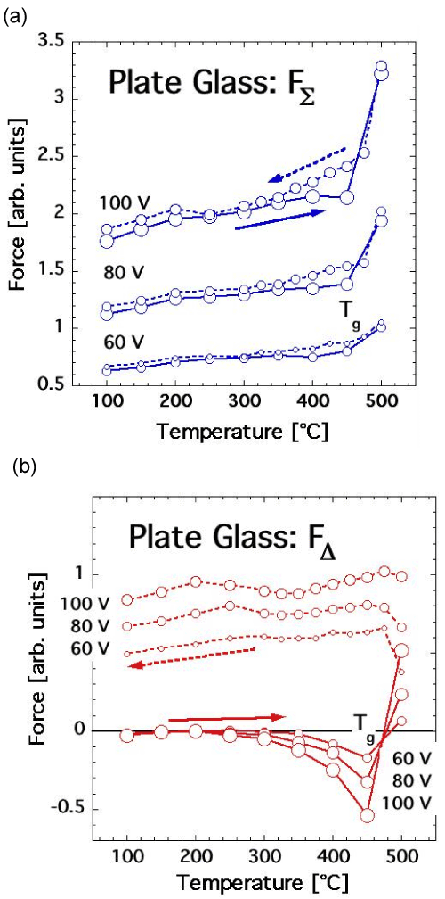
| Figures 9a and 9b shows the FΣ (T) and FΔ (T) responses of plate glass heated to 500°C. FΣ (T) initially exhibits only an overall increasing trend consistent with the expected increase in the polarizability as a function of T. Above the glass transition temperature Tg, when the glass structure softens, FΣ (T) increases sharply, due to an increase in Plocal as a result of the increase in diffusivity of Na+ and other alkali cations. FΣ (T) is mostly reversible under the conditions of the experiment with some hysteresis during cooling below Tg. The reason for the slight deviation from a linear FΣ (T) increase/decrease around 200°C is unknown. The overall FΣ (T) response of the glass is distinctly different from the FΣ (T) behavior of either feldspar minerals shown in figure 8a and 8b. There is no evidence for any FΣ (T) increases characteristically linked to a 2-step activation of peroxy defects. |
| This conclusion is supported by the FΔ (T) response of the glass shown in figure 9b. During heating a negative surface charge develops, which changes abruptly to a positive surface charge above Tg. The evolution of FΔ (T) towards positive values is due to the high diffusivity of Na+ and other alkali cations in the externally applied divergent E field. The Na+ segregation is irreversible during cooling down to room temperature as demonstrated by the persistence of the positive FΔ (T) values in Figure 9b. |
| The lack of evidence for peroxy defects in the dielectric polarization response of normal plate glass is consistent with the overall theme of this study: Peroxy defects are formed metastably out of solute OH–, O3Si-OH, or O3Al-OH, presumably hydroxyl pairs, which undergo a redox conversion during cooling. This reaction takes place in materials compositionally and structurally as varies as MgO and feldspars. It also takes place in glasses. For instance, fused silica, which dissolves traces of H2O at a much higher temperature than ordinary plate glass, has been shown to contain peroxy defects and to activate positive hole charge carriers in much the same way as MgO [71]. |
| Peroxy Defects in even more Reduced Minerals |
| The dielectric polarization behavior described in the preceding section indicates the presence of mobile positive hole charge carriers in MgO and feldspar crystals but not in regular plate glass. It provides unambiguous support for the presence of peroxy defects in MgO grown from the melt under the extremely reducing conditions of a carbonarc fusion furnace [44] and in feldspar specimens that crystallized in magma under reducing lower crustal conditions. The dielectric polarization response is consistent with the electrical conductivity behavior of the melt-grown MgO crystals. It is fully consistent with our conclusion from the first part of this paper that positive hole are the charge carriers, which control the electrical conductivity in the LT region, up to about 600°C, of MgO and of mafic and ultramafic rocks. |
| This study points to a mechanism by which crystals grown under reducing, even extremely reducing conditions, can acquire peroxy defects. The peroxy defects are introduced via the dissolution of H2O. The dissolution of H2O, however, is very common in nature, taking place whenever minerals and rocks crystallize from any H2O-laden melt or magma. |
| Peroxy defects and positive hole charge carrier activation in olivine |
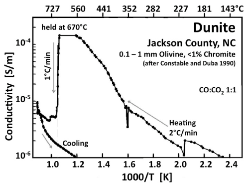
| The electrical conductivity of dunite, an olivine-rich peridotite, is illustrated in figure 10, adapted from work by Constable and Duba [49]. During heating in a 1:1 CO:CO2 atmosphere, the conductivity increases rapidly between ~350°C and 670°C. At 670°C, as T was held constant for an unspecified length of time, the conductivity decreased precipitously. During further heating the conductivity increased again, merging into a high temperature branch similar to the HT branch observed with MgO. During cooling the beginning of an Arrhenius straight section can be seen with activation energy of ~1 eV characteristic of the LT conductivity response of MgO. |
| The interpretation is based on the assumption that, during heating, carbon was depositing out of the vapor phase onto the sample surface, providing a low resistivity pathway [49]. The carbon deposition is assumed to have ended at 670°C when, according to thermodynamic calculations, the 1:1 CO: CO2 mixture was leaving the stability field of graphite, creating oxidizing conditions, which caused the surface carbon film to “burn off”. No experiments with interruptions of the overall heating and repetitive intermittent cooling/reheating cycles have been reported that could have shed light on the assumption of carbon films can be sustained. |
| We therefore present next the dielectric polarization response of an olivine single crystal. To avoid complications arising from carbon precipitation in the graphite stability field we chose to conduct the first set of experiments in high purity N2. The choice of an inert gas atmosphere is justified on the basis of the observation that the CO:CO2=1:1 mixture anyhow remained unequilibrated up to at least 500°C [49] and therefore has little or no effects on the sample. The sample was prepared by cutting a 1 mm thick slice, 8 mm diameter, from a randomly oriented cylinder of a gem-quality San Carlos olivine single crystal, 7 mm thick, polished on both sides. Before the slice was cut off, the IR spectrum was recorded. |
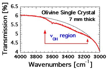
| As shown in figure 11 the broad absorption in the spectral range of the νOH stretching vibrations, 3150-3700 cm-1, lacks distinct features except for a weak band at 3600 cm–1. The absence of νOH bands is conventionally interpreted to mean that such an olivine crystal without OH– has a very low solute “water” content and may have come from a “dry” of the upper mantle [17]. However, there is also the possibility that, similar to OH– pairs in MgO, solute OH– in olivine may have converted to H2 plus peroxy defects. In this case the near-absence of νOH bands may mean that an olivine crystal with an IR spectrum as exemplified in figure 11 may have lost most of its solute OH– content due to this redox conversion. If the solute OH– content was originally high, the olivine should have a high concentration of peroxy defects. Measuring the dielectric polarization would then be the technique of choice [64]. |
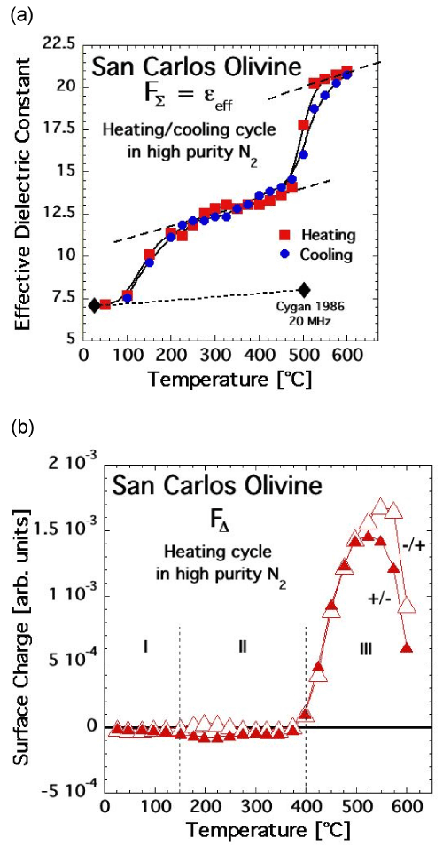
| Figures 12a and 12b show FΣ(T) and FΔ(T) of this olivine crystal, recorded according to the protocol outlined in figure 5 with 15 sec polarization time at each ΔT and ΔV step. FΣ(T) is fitted at room temperature to a dielectric constant ε scale. Because the orientation of the olivine single crystal under study is not determined, the data were fitted the average of the three components of the dielectric constant ε of forsterite along the crystallographic axes a, b, and c [72]. |
| FΣ(T) of this olivine crystal is strikingly similar to FΣ(T) of MgO and of the two feldspar specimens. During heating, the bulk polarization increases in a stepwise fashion at 100-250°C and 450-500°C. During cooling, FΣ(T) follows closely the heating curve down to at least 100°C. |
| FΔ(T) recorded is also strikingly similar to FΔ(T) of MgO and the feldspars. The curves labeled +/- and -/+ correspond to FΔ values obtained during heating taking the data from the sections going in ΔV steps from +500 V to –500 V and from –500 V to +500 V, respectively. The difference between the two FΔ(T) curves provides information about the time-dependent polarization during the 15 sec time steps. FΔ(T) remains close to zero from 100°C to almost 400°C, while FΣ(T) goes through its first stepwise increase. Thus the first FΣ(T) increase is due to a Plocal contribution to Pbulk, without activation of mobile charge carriers. Mobile charge carriers only appear upon approaching 400°C as evidenced by the evolution of FΔ(T) toward positive values. At first the number of mobile charge carriers is small, insufficient to cause a noticeable increase in FΣ(T). By about 450-500°C their number has increased enough so that FΣ(T) increases, due to a Pspace contribution to Pbulk. The sign of the mobile charges in the olivine is unambiguously positive, as in MgO and the feldspar specimens, providing firm evidence that positive holes are the active charge carriers. |
| Metastability and thermodynamic equilibrium in olivine |
| The very weak IR absorption of a 7 mm thick olivine crystal in the range of νOH stretching vibrations as evidenced by figure 11 indicate a near-complete absence of solute OH–. The same olivine crystal provides evidence for positive hole charge carriers that become thermally activated at about the same temperature at which positive holes are activated in MgO. This suggests that the charge carriers are positive holes and that they derive from peroxy defects in the olivine matrix, formed by the same type of redox conversion that turned OH– in MgO into O2 2–+H2 as given by eq. (13). For olivine we have: |
| where the # sign is used to indicate a divalent cation vacancy, Mg2+ or FE2+ |
| By analogy to the dilute solid solution MgO–H2O, we formulate a dilute olivine– H2O solid solution as: |
| (Mg, FE2+) 2SiO 4 +δH2O⇔(Mg, FE2+) 2–δ SiO 4-2δ OH 2δ (24) |
| If the OH– in this olivine– H2O solid solution undergoes a redox conversion according to eqn. (23) and if some or all of the molecular H2 is lost from the crystal matrix by out diffusion, we have: |
| (Mg, FE2+)2–δ SiO 4-2δ OH 2δ ⇔(Mg, FE2+)2–δ SiO4+δH2 (25) |
| where we do not separately indicate on the right hand side the fraction of oxygen in the valence 1–. We specify, however, that iron continues to be ferrous, FE2+. In order for the cation-deficient olivine on the right hand side to be balanced, a 2δ fraction of the oxygens have to be in the valence 1-. |
| Low solute OH– concentrations are usually interpreted to mean that such crystals come from “dry” regions of the upper mantle [73-75]. Eq. (25) suggests instead that solute OH– may have “disappeared” from the IR spectra by converting to H2 plus peroxy. Molecular H2, if present, has extremely weak νH-H absorption [76]. Other techniques such as SIMS or nuclear reaction profiling, which measure the total H concentration, often yield higher H values than those obtained by IR measurements of νOH [77]. This apparent conflict has been “solved” by adjusting the calibration curves for the concentration of OH– versus the intensity of the νOH band. |
| “Burning off” positive holes in olivine |
| If the enhanced electrical conductivity observed during initial heating were due to carbonaceous films precipitated within the stability field of graphite [10], such films should “burn off” under oxidizing conditions. If the enhanced electrical conductivity is due to h•, i.e. highly oxidizing O– in a matrix of O2-, the best way to annihilate them is to introduce reducing conditions. |
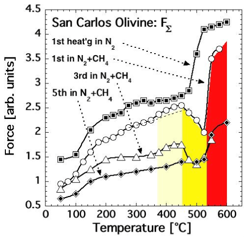
| We therefore conducted another dielectric polarization experiment with a San Carlos olivine single crystal, heating it first in pure N2 atmosphere in 20 temperature steps from 50°C to 600°C, cooling it back in the same steps, and letting it sit overnight in the pure N2. FΣ(T) as recorded during this first heating is shown in figure 13a by the top curve labeled with squares. |
| Next we replaced the N2 with a 9:1 N2-CH4 gas mixture and reheated the same olivine crystal several times. The 1st heating in N2-CH4, up to 575°C, produced the FΣ(T) curve marked by open circles in figure 13a. After stepwise cooling the olivine crystal was reheated in the same N2-CH4gas mixture four more times. The 3rd heating up to 550°C produced the FΣ(T) curve shown in figure 13a by open triangles. The 5th heating up to 600°C produced the FΣ(T) curve in figure 13a marked by diamonds. |
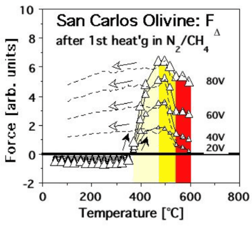
| Figure 13b shows FΔ(T) curves recorded during the 1st heating in the N2-CH4mixture with different bias voltages. The FΔ(T) response during heating displays the same overall pattern as observed for MgO and the feldspar specimens. The dashed lines present the FΔ(T) response during cooling: fully reversible from 600°C to about 500°C, followed by elevated FΔ(T) values below 400°C due to the fact that, after heating in the N2-CH4 mixture, the positive surface charge no longer dissipates after cooling. |
| Comparing the FΣ(T) response during the 1st run in pure N2 and the subsequent runs in the N2-CH4 gas mixture provides insight into the reactions at the olivine surface. Figure 13a shows that, during repetitive heating in the presence of CH4, the FΣ(T) response up to about 450°C is similar to FΔ(T) measured under pure N2, although the curves shift lower with every reheating cycle. The overall decrease of FΣ(T) is noticeable already after the 1st heating in pure N2, presumably because some oxidation occurred in the olivine matrix changing FE2+into Fe3+by consuming some of the available mobile h• charge carriers. |
| During each reheating in the N2-CH4gas mixture FΣ(T) drops precipitously, indicating that more h• charge carriers are being consumed. Above 530°C however, FΣ(T) increases again, indicating that the surface reaction, which consumes h• charge carriers, has stopped. This behavior, in particular the dip of FΣ(T) between 450- 500°C, repeats itself during the 3rd heating cycle. By the time of the 5th heating the dip has essentially disappeared, indicating that the reaction between the olivine and CH4 has reached some form of endpoint. |
| The areas highlighted in pale yellow in figures 13a and 13b mark the ΔT range when FΣ(T) continues to increase even though the FΔ(T) curves show that h• charge carriers are already flooding the olivine surface. FΣ(T) begins to dip in the ΔT range marked in bright yellow, i.e. after the FΔ(T) values have reached their maxima. The area marked in red outlines the ΔT range, where FΣ(T) recovers, rising in spite of the presence of CH4. |
| Summarizing this last set of experiments we can say with additional confidence that, though the olivine crystal under study originated in the upper mantle and has crystallized in a highly reducing environment, it releases highly oxidizing h• charge carriers upon heating. The h• charge carriers are consumed by a reaction with CH4, presumably through oxidative coupling, which produces OH– and methyl as an intermediate, •CH3 [78]. From these observations we infer that the upper mantlederived olivine contains peroxy defects. Since it is thermodynamically impossible to introduce highly oxidizing O– under the highly reducing conditions of the upper mantle, the peroxy defects much have been introduced during cooling, presumably by way of a redox conversion of OH– pairs incorporated into the olivine structure through dissolution of traces of H2O. This is consistent with the observation that the olivine crystal under study appeared to be almost completely devoid of OH– as documented in figure 11. The reason for the absence of solute OH– is not that this particular olivine crystal came from a “dry” region of the upper mantle but that the overwhelming majority of its solute OH– had been converted to peroxy defects plus H2. This in turn is consistent with the observation that San Carlos olivine crystals, when crushed, release copious amounts of H2 both during crushing and during subsequent heating at modestly elevated temperatures [79]. |
| Discussion |
| In this paper we have focused on fundamental processes that are important for understanding the electrical properties of materials, both single crystal minerals and igneous rocks, both laboratory- grown and from natural environments. We make the extraordinary and seemingly paradoxial claim that MgO crystals, grown from the melt under the viciously reducing conditions of a carbon arc fusion furnace, contain peroxy defects in their crystal structure, hence oxygen in the valence state 1–. When the peroxy defects break up, they release positive hole charge carriers, formally defect electron in the oxygen anion sublattice, equivalent to O– in a matrix of O2–. These positive holes have two outstanding properties: they are highly mobile and highly oxidizing. |
| We make the additional, seemingly even more extraordinary claim that olivine crystals, which have been brought up from the upper mantle by volcanic eruptions, feldspar crystals, which have been brought up from the lower crustal depth, also by volcanic eruptions, and more generally-mafic/ultramafic rocks such as basalts, gabbro and peridotite produce the same type of mobile positive hole charge carriers and, hence, must contain peroxy defects. This claim seems to run counter to the well-established fact that upper mantle and lower crustal environments are known to be highly reduced and highly reducing. Therefore, thermodynamically, oxygen in the valence state 1– characterizistic of peroxy should never be introduced under these conditions-if the O– were to be introduced in situ. |
| In fact there is no contradiction with thermodynamics. The reason is that the process, which is allowable under in situ conditions, even in highly reduced environments, is the dissolution of H2O. H2O becomes always incorporated into the matrix of any oxide crystal growing from a melt and into any silicate crystallizing from magma. The reason is that such melts or magmas invariably contain dissolved H2O. During crystallization, solute H2O partitions between the solid and the liquid phase. The solid state dissolution of H2O and formation of solute OH– or O3Si-OH are redox insensitive. According to our findings O– is introduced through a follow-on process, the redox conversion of hydroxyl pairs to peroxy defects plus H2. This process only occurs at much lower temperatures, under metastable conditions, during cooling when the systems drift out of thermodynamic equilibrium. |
| Depending upon the rate at which a rock or a crystal is cooled, thermodynamic equilibrium can only be maintained as long as diffusional processes remain thermally activated. Diffusional processes are necessary for the adjustment of the oxidations states of transition metal cations and the adjustment of the cation vacancy concentration, both dictated by the oxygen fugacity of the system. Without these continuous adjustments any system will be out of thermodynamic equilibrium. Even at very slow cooling rates these diffusional processes become so slow around 600°C that they can be considered frozen2. At faster cooling rates the freezing temperatures tend to be higher, more in the 700°C range. Since the redox conversion as outlined by eqs. (13) and (23/25) operate outside equilibrium, oxygen in the valence 1– can exist metastably in an otherwise reduced environment. It can co-exist with reduced cations such as FE2+. At the same time O– form highly mobile electronic charge carriers within certain temperature windows, which affect the electrical conductivity behavior. Therefore positive hole charge carriers are of interest to the electric structure of the Earth’s crust. |
| The work presented here casts doubts on the validity of the widely offered explanation that the conductivity of the rocks is controlled by thin carbonaceous films deposited from CO/CO2- laden fluids in the crust [12,80] and upper mantle [10,31,50,81], or by aqueous fluids filling the intergranular space. Maybe such intergranular conductive phases are not needed to account for the zones of high electrical conductivity, which seem to exist in the lower continental crust [19,22,28] and have been called “a long-standing mystery” [82]. |
| If peroxy defects and thermally activated positive hole charge carriers can be metastably present, we can tie the high conductivity zones to the geotherm [83]. If temperatures along the geotherm reach values sufficiently high to thermally dissociate peroxy defects and release positive hole charge carriers, we can envision a depth range, where the peroxy defects would be in a permanently dissociated state. With reference to eq. (7) this means an increase in the number n of mobile charge carriers and, hence, an increase in the conductivity σ. Deeper into the crust, at temperatures at which thermodynamic equilibrium prevails, the positive holes will be consumed by equilibrium oxidation reactions, for instance FE2+ to Fe3+, concomitant with structural rearrangements that require thermally activated cation and cation vacancy. |
| An analogous situation is seen in the experimental conductivity curves obtained during heating of MgO single crystals as depicted in figures 3a, 3c, and 3d: at temperatures above 500-700°C the electrical conductivity decreased precipitously because the h• charge carriers begin to be consumed by reactions linked to the return of the MgO crystals toward equilibrium. The same behavior is reflected in the conductivity curve recorded during heating of an olivine single crystal as depicted in figure 9, even though the authors of this graph base their interpretation of the conductivity decrease at 630°C on the assumption that vapor-phase deposited carbon films on the sample surface were being “burnt off” as the system moved out of the stability field of graphite in the CO:CO2 gas mixture to more oxidizing conditions [10]. The dielectric polarization behavior of the olivine single crystal heated in a CO:CH4 gas mixture as depicted in figure 13a and 13b indicates that h• charge carriers are being consumed not under oxidizing but under highly reducing conditions-in this case h• reacting with CH4 by way of an oxidative coupling that produces OH– and methyl as an intermediate, •CH3 [78]. |
| Acknowledgements |
| The ideas expressed in this paper evolved over many years out of work, which was in part supported by grants from the NASA Earth Surface and Interior (ESI) program to FF. |
References
|
Figures at a glance
 |
 |
 |
 |
 |
| Figure 1a | Figure 1b | Figure 2a | Figure 2b | Figure 3 |
 |
 |
 |
 |
| Figure 4 | Figure 5 | Figure 6 | Figure 7 |
 |
 |
 |
 |
| Figure 8a | Figure 8b | Figure 9 | Figure 10 |
 |
 |
 |
 |
| Figure 11 | Figure 12 | Figure 13a | Figure 13b |
Relevant Topics
- Atmosphere
- Atmospheric Chemistry
- Atmospheric inversions
- Biosphere
- Chemical Oceanography
- Climate Modeling
- Crystallography
- Disaster Science
- Earth Science
- Ecology
- Environmental Degradation
- Gemology
- Geochemistry
- Geochronology
- Geomicrobiology
- Geomorphology
- Geosciences
- Geostatistics
- Glaciology
- Microplastic Pollution
- Mineralogy
- Soil Erosion and Land Degradation
Recommended Journals
Article Tools
Article Usage
- Total views: 16727
- [From(publication date):
November-2012 - Nov 15, 2025] - Breakdown by view type
- HTML page views : 11816
- PDF downloads : 4911
