Research Article Open Access
Design and Prototype Development of a 1-DOF Flapping-foil & Gliding UUV
Ding Hao*, Song Bao-wei and Cao Yong-huiCollege of Marine Engineering, Northwestern Polytechnical University, Xi’an 710072, China
- *Corresponding Author:
- Ding Hao
College of Marine Engineering
Northwestern Polytechnical University
Xi’an 710072
China
E-mail: hao_shreck@163.com
Received date: December 27, 2011; Accepted date: March 08, 2012; Published date: March 13, 2012
Citation: Hao D, Bao-wei S, Yong-hui C (2012) Design and Prototype Development of a 1-DOF Flapping-foil & Gliding UUV. J Marine Sci Res Development S10:001. doi:10.4172/2155-9910.S10-001
Copyright: © 2012 Hao D, et al. This is an open-access article distributed under the terms of the Creative Commons Attribution License, which permits unrestricted use, distribution, and reproduction in any medium, provided the original author and source are credited.
Visit for more related articles at Journal of Marine Science: Research & Development
Abstract
The main objective of this paper is to investigate an underwater unmanned vehicle (UUV) which has both flapping-foil and gliding function. Firstly, the paper introduced the advantages of the flapping-foil & gliding UUV, and described the flapping-foil motion model of bionic object turtle in detail. Then, by using the dynamic meshing technology in the code Fluent, the numerical computations of unsteady hydrodynamic characteristic for single degree of freedom (1-DOF) flapping-foil movement was carried out, which demonstrated the mechanism of flapping- foil. During the computation, turbulence effects were taken into account, and the turbulent stressed was evaluated by means of the Realizable k-epsilon model. Finally, the kinematics simulation of the UUV was performed. The design on virtual prototype of the UUV was completed in UG software, and the prototype was processed in the digital factory. Moreover, we presented the corresponding solutions aiming at the problems of the assembly prototype.
Keywords
Underwater unmanned vehicle (UUV); Bionic; Flappingfoil; Gliding; 1-DOF
Introduction
The traditional propeller used by most of the UUVs has a broad field of application of the ship. However, the maneuverability and speed performance of the propeller still need to be improved. Considering the complicated environment of the seabed in marine engineering, such as undercurrent, wave, bay area, etc., the traditional propelleris not able to meet the requirements of the modern marine operations [1].
In recent years, the flapping-foil technology and underwater gliding technology have been developed independently, and some achievements are also obtained, which can partially overcome the subsistent problems of the traditional propeller well.
The physics of beat and flying focus on the considerable theoretical, numerical, and experimental work. Experimental work with live fish [2- 4] and biorabotic devices modeled on the blue-fin tuna [5], and smallmouth bass [6] have been studied extensively. One of the motivations has been to improve the design and performance of underwater vehicles, recognizing that in many ways there is an extraordinary gap between the abilities of man-made machines and other marine animals. Quantitative comparisons between the hydrodynamics of fish and small underwater vehicles have been formulated [7]. Extensive testing of oscillating foils has been performed in the Massachusetts Institute of Technology (MIT) Ship Model Testing Tank, resulting in a solid understanding of the fundamental parameters of thrust production in foils [8-10], and design and projected performance of the flapping-foil AUV [11,12] has also been studied.
The concept of underwater glider was envisioned in 1989 [13], then three operational gliders have been developed, including the Slocum Battery/Thermal glider [14], the Spray slider [15] and the Sea glider [16], which change their volume and buoyancy to cycle vertically in the ocean and use lift on wings to convert the vertical velocity into forward motions [17].
However, the research on combining technology of these two propulsion technologies is few in the literatures. It will become an important direction that how to compromises the merits of this two technologies. In this paper, we present a 1-DOF flapping-foil & gliding UUV, which imitates the swimming mechanism of some marine animals such as turtles, penguins and seals. It is a new concept UUV combines flapping-foil technology with underwater gliding technology, which has many advantages including high efficiency, high stability, high maneuverability, long range and so on.
As part of the development of the UUV, this paper carried out numerical simulations to investigate the mechanism of flapping foil propulsion. Besides, virtual design and the prototype manufacture were introduced. Finally, motion simulations were proposed to evaluate the motion performance of the vehicle.
Motion Mode of Bionic Object
In this paper, the UUV was designed with green turtles as bionic object. Swimming in the water, the turtle generates thrust mainly relying on the forelimb stroking, while after-limb only plays the role of the rudder. There are three basic swimming forms of the turtle, such as horizontal straightline movement, turning and heaving. The most typical movement pattern is the horizontal straightline, and the other two movements are just auxiliary motions basing on the motion of horizontal straightline. That is, the forelimb has different flapping frequency and amplitude to cooperate with the motion of the afterlimb in the turning and heaving motions.
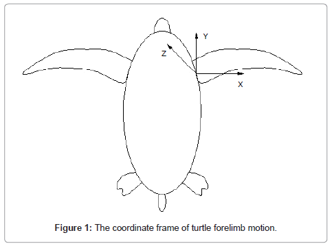
In order to give an intuitive description of the forelimb motion mode when the turtle moving in a horizontal straightline, we assign a Cartesian coordinate system O-XYZ fixed to the turtle body with its origin at the root point of the forelimb, as shown in Figure 1. Let axis Y parallel the long axis of the turtle (positive in the direction of the turtle’s nose), and axis Z, which points to the top, lie in the longitudinal plane and perpendicular to axis Y. Axis X points in the direction orthogonal to Y-Z plane [18].
In generally, swimming straight and level, the forelimb motion mode contains three kinds of rotation around X-axis, Y-axis and Z-axis, respectively. The rotation around Y-axis makes turtle forelimb beat water up and down; the rotation around X-axis makes the forelimb pitch and change angle of attack of the forelimb; the rotation around Z-axis makes the forelimb stroke forward and backward, while the range is relatively narrow. All these three cooperative rotations make the turtle get a continuous forward thrust, and the motion mode has three degrees of freedom (3-DOF).
Numerical Simulation of 1-DOF Flapping-foil Motion
Mathematical model of 1-DOF flapping-foil motion
This paper simplified the complex 3-DOF flapping-foil motion of turtle to 1-DOF flapping mode, and considered that the foil was rigid in free boundary flow. Defining the foil flapping according to the sine law, the expression of the flapping angle displacement [19] is:
θ(t)=θ0sin(2πft+ψ)+θbias (1)
Where θ0 is the foil flapping amplitude, f is the frequency, ψ is the initial phase angle. θbiasis used to change the equilibrium position of the foil flapping, which leads to a change of the direction of the thrust produced by the flapping-foil motion.
The expression of the angle velocity of flapping-foil can be derived by differentiating with respect to θ(t):
ω(t)=2πfθ0 cos(2πft+ψ)(2)
Computational domain and grid system
Computational domain and grid system
1500mm×1500mm×1500mm
Inlet boundary conditions: velocity inlet;
Outlet boundary conditions: outflow;
Other boundary conditions: wall.
Using the dynamic meshing technology in the code Fluent, the numerical simulation of unsteady hydrodynamic characteristic for 1-DOF flapping-foil motion can be carried out by solving the incompressible Navier-Stokes equations numerically in a non-inertial reference frame. During the computation, turbulence effects were taken into account, and the turbulent stressed was evaluated by means of the Realizable k-epsilon model.
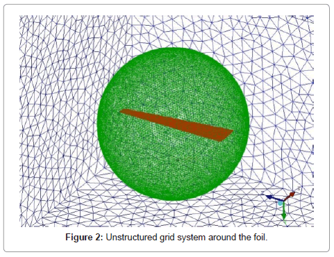
Since the dynamic meshing technique should base on the unstructured grid system, we discretized the computational domain into the unstructured grid using the ANSYS ICEM software. In the process of computation, the unstructured grids were updating with every time step by spring-based smoothing method and local remeshing method. To improve the quality of the mesh updating, a spherical interface was set to divide the computational domain into two parts. Moreover, to increase the calculation accuracy, the meshes near the surface of foil wall were refined. The grid system is shown as Figure 2.
Calculation results and analysis
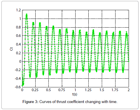
For the motion object, the foil is three-dimensional and rigid, and the airfoil profile of section is NACA0010. Its root chord is cmax=70mm, and tail chord is cmin=1/3cmax, i.e., the chord shrinks in a proportion 3:1 in the direction of span. To explore the change principle of the thrust produced by the flapping-foil motion with time increasing, numerical simulation was carried out in the conditions that the coming flow velocity is U=0.01m/s, the amplitude of beat is θ0=30º, and the frequency is f=4Hz. Figure 3 shows the curve of the thrust coefficient Ct changing with time.
The time step of this numerical example was set as 0.002s with total 1000 steps. The flapping-foil motion lasted 2s from start to end and had eight full periods. After the third period (0.75s), the flow field was tending to steady. It can be seen from Figure 3:
(1) At the beginning of the flapping-foil motion, thrust coefficient is negative, which shows the drag is produced at this moment;
(2) In one period of the motion, two peak values of the thrust and two peak values of the drag (Ct<0) are observed;
(3) In one period, the average thrust coefficient is positive, which means the continuous flapping-foil motion can produce a continuous thrust for the UUV.
(4) Periodicity has been found from the curve of the thrust coefficient changing with time, and its frequency is twice as much as that of the flapping-foil motion.
Influence of motion parameters on thrust
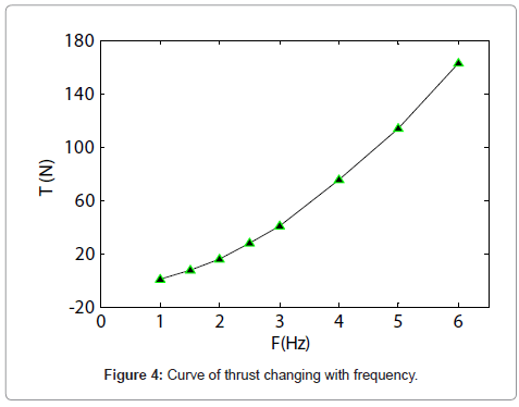
Relationship between frequency and thrust: When coming flow velocity U=0.2m/s, and the amplitude θ0=30º, thrusts are calculated in the cases when the frequency f are 1Hz, 1.5Hz, 2Hz, 2.5Hz, 3Hz, 4Hz, 5Hz and 6Hz, respectively.
Figure 4 shows that in the case when other parameters are identical, the average thrust is approximately a square function of flapping frequency, Tαf2. That is, since the frequency increases, the work done on the fluid is also increases, which leads to a raise of thrust.
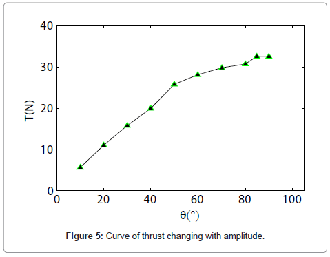
Relationship between amplitude and thrust: When coming flow velocity U=0.2m/s, and flapping frequency, f=2Hz thrusts are calculated in the cases when the amplitude θ0 are 10°, 20°, 30°, 40°, 50°, 60°, 70°, 80°, 85° and 90°, respectively.
As can be seen in Figure 5, thrust gets larger as the amplitude increases, but the changing rate slows down when θ0 >50°, and the thrust approximately stayed the same when θ0 >85°. This can be explained as when the amplitude increases, the resistance on the foils evidently increases and the thrust generated mainly contributes to counteract the resistance.
Virtual Design of 1-DOF Flapping-foil & Gliding UUV
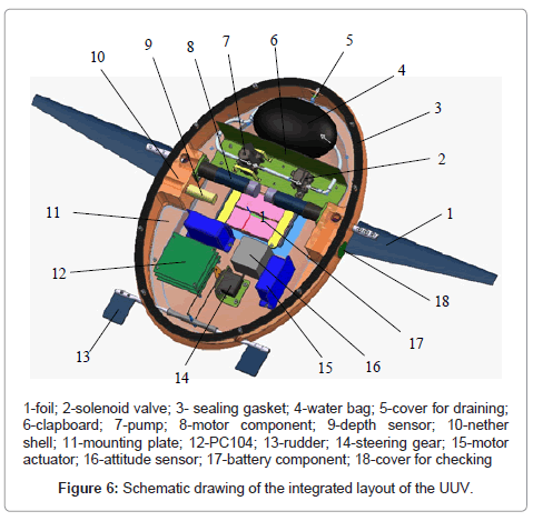
The overall structure of the 1-DOF flapping-foil & gliding UUV designed in this paper mainly included five parts: (1) main body and accessories; (2) 1-DOF flapping-foil thruster; (3) glide control system; (4) steering gear structure; (5) control and communication system. The idea of modular design was adopted for each part, which has many advantages such as high reliability, easy for assembly and disassembly, excellent expansibility. Figure 6 shows the integrated layout of the UUV [20].
Main body
The design of the main body can be divided into the following parts: configuration design of pressure shell, material selection of the shell, design of seal, and optimization of interior space, etc.
From a bionic standpoint, we selected ellipsoid as the configuration of the pressure shell in consideration of the maneuverability, running resistance, internal installation space of the UUV. Except the foil, the designed UUV had a total length of 600 mm, width of 420 mm, height of 220 mm, and minimum wall thickness of 10 mm, hence the external offsets of configuration is:
 (3)
(3)
The shell consisted of two parts, where the joint of the upper and nether was sealed with rubber gasket, and the shafts with foil and rudder were sealed with O-shape seal ring. The good sealing properties ensured that the security of the internal space to install various devices and apparatuses. In order to save space and make the center-of-gravity position of the UUV easier to control, a mounting plate fixed on the nether shell was designed for laying up most of the devices. Considering the fabrication, procedure and work environment of the UUV, we selected cemented aluminum alloy as the material of pressure shell.
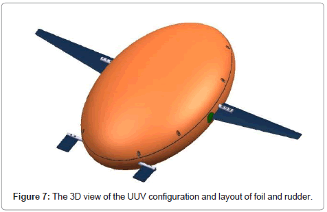
Swimming in the water, the turtle promotes thrust mainly relying on the forelimb stroking, and the after-limb only plays the role of rudder. According to this point and the requirement of gliding movement, the 1-DOF flapping-foil thruster was laid at both sides of the UUV away from the centerline 50 mm forward, and the rudder 250 mm backward, as shown in Figure 7.
1-DOF flapping-foil thruster
When the flapping-foil & gliding UUV was sailing underwater, the thruster can be used as a machine to generate power by flappingfoil motion to make the UUV in high mobility, or a glider to provide enough lift for the UUV gliding. Thus, the design of flapping-foil thruster is primary.
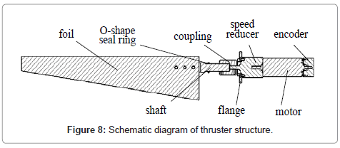
The 1-DOF flapping-foil thruster consisted of multiple components such as foil, shaft, coupling, speed reducer, motor etc. Relying on lithium batteries to provide power source, the motor drove the speed reducer to transfer the rotation to shaft through the coupling, and the foil was flapping with the shaft. The schematic diagram of thruster structure is shown in Figure 8. Then, the UUV could realize the function of gliding, when the foil was fixed in a prescribed station by motor selflock and the centre-of-gravity adjustment device was working. This design reduced the driving medium from motor to the foil, therefore the transmission efficiency and accuracy were improved dramatically. It made the thruster in a very compact form and service life longer, however, this form required the high coaxiality of the motor shaft, foil shaft and mounting hole in the shell, which increased the difficulties in processing and assembly. In this paper, we ensured the high coaxiality requirement by increasing a shaft shoulder in the mounting motor flange.
To select the suitable motor for driving the foil, nominal power and maximum torque of the motor should be estimated. The foil was reduced to a trapeziform plate, and we selected a rectangular differential element with an area of dA on the plate in the direction of span. When the foil flapping, the drag on the element can be written as:
 (4)
(4)
Where, CD=1.2 is the coefficient of viscosity of rectangular plate, ρ=1000kg/m3 is the density of water, and l is the span of foil. Since dA=cdl, V∞=ω(t)l, we have
 (5)
(5)
The torque that the element on shaft is:
 (6)
(6)
The total torque of the motor overcoming the drag can be obtained by integrating dM in the direction of span, and the power of motor is:
P=Mω(7)
Taking gravity of the foil into consideration, we substitute the maximum frequency fmax=5 and the maximum amplitude ?0=π/2 into the equation, then the nominal power and maximum torque of the motor were calculated as 42.6w and 2.3Nm, respectively. Finally, we selected the DC servo motor RE30 manufactured by Maxon Corporation in Switzerland.
This 1-DOF flapping-foil thruster makes the UUV designed have many advantages including high efficiency, high maneuverability and long range. However, the thruster has the following limitations: (1) it applies only to small UUVs and provides a relatively lower velocity, (2) the structure is complicate and (3) the control system is complex.
Glide control system and steering gear structure
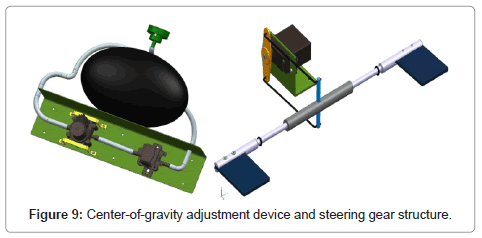
Glide control system depended on the center-of-gravity adjustment device to control the angle of attack of the UUV, and it consisted of bump, solenoid valve, controller, switch, water bag and so on. Glide is an important function of the flapping-foil & gliding UUV. Cooperating with the flapping-foil motion, it can both improve the high mobility and save the energy source to ensure a long range. Generally, sliding straight at low speed, the value and the center of buoyancy of the UUV are constant. Thus, in the situation without power, using the device to change the gravity and the relative position with the center of buoyancy, the lift for gliding is produced when the angle of attack of the UUV changed [21]. The steering gear structure laid on the rear end of the UUV can be used to give a fine-adjustment to attitude of the UUV, which makes it slide according to a predetermined trajectory.
Control and communication system
Control and communication system consisted of hardware circuitry and matching software. For processing various kinds of information effectively, a high performance central processing unit PC104 and buffer circuit were used, including various I/O ports and internal Bus. All sensors and devices, including depth sensor, motor actuator, and attitude sensor and so on, were connected to the Bus through the I/O ports. With the help of the software to conduct the real time information interchange, each module of the flapping-foil & sliding UUV can work independently or in parallel (Figure 9).
Kinematics Simulation of the 1-DOF Flapping-foil & Gliding UUV
In this section, by constructing a kinematics model for the designed 1-DOF flapping-foil & gliding UUV, the analysis of kinematical performance was studied when the UUV was cruising underwater in flapping-foil propulsion way and gliding way.
Kinematics simulation in flapping-foil working state
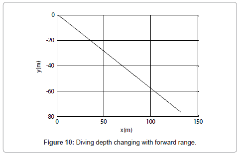
The kinematics simulation of the UUV diving with a negative angle of attack of 30° had performed in the conditions that the two thrusters are working together with the same frequency f=5Hz and amplitude Φ0=π/4.
From Figure 10, we can see that the UUV has dived for 60m when going forward for 100m. The UUV has a bumpy movement at the initial stage, but after a short time, it dives in a straightline with zero angle between the equilibrium position of the foil flapping and the horizontal axis plane of the UUV.
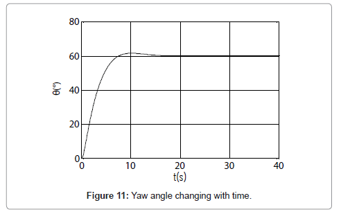
To make the UUV turn left for 60°, we set left foil flapping in frequency 3Hz and right foil in a changing frequency 4Hz~0Hz. As shown in Figure 11, the UUV has turned 60° to the left within less than 10s, and then it is sailing with a yaw angle for 60°. This simulation result illustrates that the UUV designed in this paper has a high motility when it works in flapping-foil state.
Kinematics simulation in sliding working state
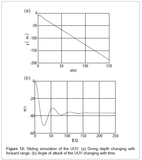
The gliding kinematics simulation of the UUV had performed in the initial conditions that delivery speed for 1m/s and the mass of water bag for 0.2kg.
It can be seen from Figure 12 (a) that the UUV has submerged for 180m when going forward for 150m in no power state. Since the mass changing of the water bag has a relative long time process, in the initial stage, the UUV has a changing angle of attack and a bumpy movement as shown in Figure 12 (a)~(b). After about 120s, the angle of attack is fixed at about 37°, and at this time the UUV begins to slide down in a approximate straight line.
Prototype Design and Manufacture
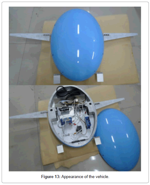
Figure 13 shows the appearance and inner structure of the vehicle. All the parts of the vehicle were processed in a NC machine. Schedule drawings of the parts were drawn by means of a commercial 3-D modeling code NX v6.0. Several problems arose during the test, and were finally solved. Among all the problems, the following ones seemed the most significant and typical:
(1) Because of the accuracy error in processing and set up, the motor shaft, foil shaft and body installing hole were not concentric, giving rise to an increase of friction force on the flapping foil. This problem was successfully solved by adding sealed shims between the flanges.
(2) Seal between the upper and nether shell. Since the preload force on the fastening screw was not balance, seal problems appeared. By adding silica gel between the rubber blanket and the shells, we achieved a good seal performance.
(3) The vehicle had been designed to be zero buoyancy, however, due to the large size, the prototype was positive buoyancy after assembling. We succeeded balanced buoyancy and gravity of the vehicle by mounting lead block inside the vehicle.
Conclusion
A novel UUV, the 1-DOF Flapping-foil & Gliding UUV was developed in this paper. Numerical simulation, virtual design with the aid of CAD software, kinematics simulation, high-accuracy process on NC machine and vehicle assembling were presented. During the test, the vehicle showed good performance. Since the control algorithm is still under developing, underwater trials will be the next step of work. Moreover, validation of the vehicle characteristics also depends on the future experiments.
Acknowledgements
The authors gratefully thank the Basic Research Foundation of Northwestern Polytechnical University and the Graduate Starting Seed Fund of Northwestern Polytechnical University.
References
- Chi DG, Yan GZ (2001) Biommetic robot research and its perspective. Robot 23: 476-480
- Fish F (1993) Power output and propulsive efficiency of swimming bottlenose dolphins. J Exp Biol 185: 179-193.
- Lauder B (1995) Speed effects on midline kinematics during steady undulatory swimming of largemouth bass, Micropterus salmoides. J Exp Biol 198: 585-602.
- Videler J (1992) Fish Swimming. Chapman and Hall London UK.
- Barrett DS, Triantafyllou MS, Yue DKP, Grosenbaugh MA, Wolfgang MJ (1999) Drag reduction in fish-like locomotion. J Fluid Mech 392: 183-212.
- Kato N (2000) Control performance in horizontal plan of fish robot with mechanical pectoral fins. IEEE J Oceanic Eng 25: 121-129.
- Bandyopadhyay P, Castano J, Rice J, Phillips J, Nedderman R, et al. (1997) Low speed maneuvering hydrodynamics of fish and small underwater vehicles. J Fluids Eng 119: 136-144.
- Anderson J (1996) Vorticity control for efficient propulsion. Ph D dissertation Dept Oceanographic Eng Massachusetts Inst Technol Cambridge.
- Read D (1999) Oscillating foils for propulsion and maneuvering of ships and underwater vehicles. M S thesis, Dept Naval Architect, Marine Eng Massachusetts Inst Technol Cambridge.
- Haugsdal O (2000) Motion control of oscillating foils for steady propulsion and starting maneuvers. M S thesis, Massachusetts Inst Technol Cambridge.
- Licht S, Polidoro V, Flores M, Hover FS, Triantafyllou MS (2004) Design and projected performance of a flapping foil AUV. IEEE J Oceanic Eng 29: 786-794.
- Schouviler L, Hover FS, Triantafyllou MS (2005) Performance of flapping foil propulsion. J Fluids Struct 20: 949-959.
- Stommel H (1989) The Slocum Mission. Oceanography 2: 22-25.
- Webb DC, Simonetti PJ, Jones CP (2001) Slocum: an underwater glider propelled by environmental energy. IEEE J Oceanic Eng 26: 447-452.
- Sherman J, Davis RE, Owens WB, Valdes J (2001) The autonomous underwater glider ‘Spray’. IEEE J Oceanic Eng 26: 437-446.
- Eriksen CC, Osse TJ, Light RD, Wen T, Lehman TW, et al. (2001) Seaglider: a long range autonomous underwater vehicle for oceanographic research. IEEE J Oceanic Eng 26: 424-436.
- Davis RE, Eriksen CC, Jones CP (2003) Autonomous buoyancy-driven underwater gliders. The Technology and Applications of Autonomous Underwater Vehicles, 37-58.
- Liu XB, Zhang MJ (2007) Research on bionic turtle hydrofoil propulsion technology of autonomous underwater vehicle. Harbin: Harbin Engineering University.
- Schouveiler L, Hover FS, Triantafyllou MS (2005) Performance of flapping foil propulsion. J Fluids Str 20: 949-959.
- Singh SN, Simha A, Mittal R (2004) Biorobotic AUV maneuvering by pectoral fins: Inverse control design based on CFD parameterization. IEEE J Oceanic Eng 29: 777-785.
- Liu K (2007) Conceptual design and study of hybrid autonomous underwater vehicle. Tianjin, Tianjin university.
Relevant Topics
- Algal Blooms
- Blue Carbon Sequestration
- Brackish Water
- Catfish
- Coral Bleaching
- Coral Reefs
- Deep Sea Fish
- Deep Sea Mining
- Ichthyoplankton
- Mangrove Ecosystem
- Marine Engineering
- Marine Fisheries
- Marine Mammal Research
- Marine Microbiome Analysis
- Marine Pollution
- Marine Reptiles
- Marine Science
- Ocean Currents
- Photoendosymbiosis
- Reef Biology
- Sea Food
- Sea Grass
- Sea Transportation
- Seaweed
Recommended Journals
Article Tools
Article Usage
- Total views: 15242
- [From(publication date):
June-2013 - Mar 31, 2025] - Breakdown by view type
- HTML page views : 10538
- PDF downloads : 4704
